Week 12:Project-1-Meshing of Door Inner Panel Challenge
AIM :
- To take the midsurface for the given component
- Assigninging the properties at the areas where it is varying
- Applying the mesh and acheieving the mesh quality under given quality criteria
Software used :
Hypermesh 2020
Theory
The inner panel door is the component which is seen in the interface between the door and the passengers seat the major part of the component is covered with the plastic the interface contains many parts like power motor , speakers , impact sensors arm rest , switches in it for which there are seen number of plastic mountings
As the material is plastic the thickness is not seen uniform it would be varying from point to point
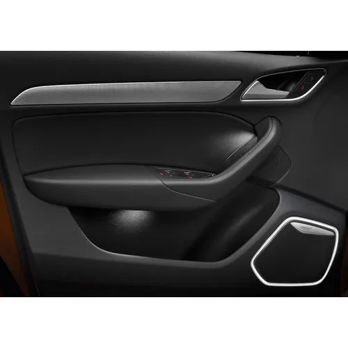
The below image show the example image of rear door panel
Procedure
Import :
the component is imported to the hypermesh data base using the import tool .
check for the geometry glitches in the geometry and and the geometric errors are evaluated by using the quick edit tools .
(import>.stp>file>import)
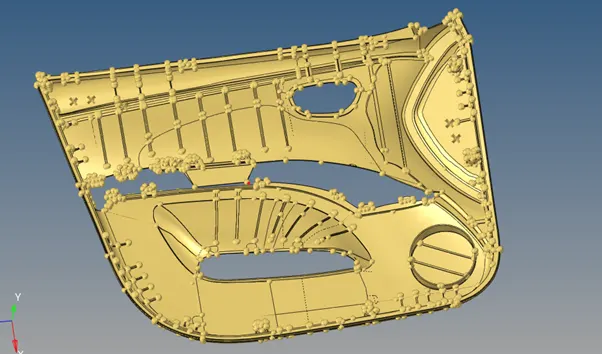
the above image shows the model imported
defeaturing
elements failing for the geometric minimum lengths are checked and defeatured using the surface defeature tools
fillets lengths under minimum length are measured and removed
(geometry >defeature>selectsurface >find>remove)
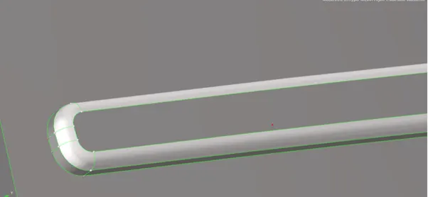
image shows the surface fillet (before) defeaturing
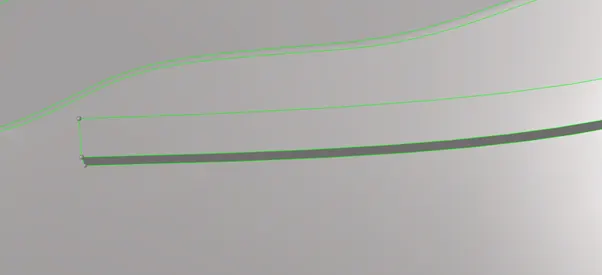
after defeaturing
Organise
In this step elements with various thickness are found out and collected into the new collector by creating the new component
(tools>organise>select the surfaces >move>into new component)
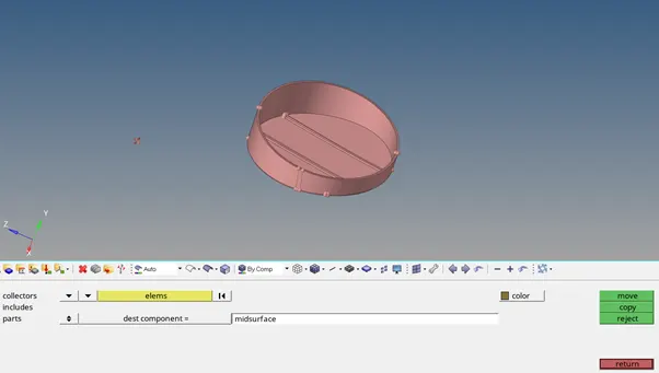
image showing the surface seperation using organise tool
Midsurface
Midsurface of the component is taken by taking average measurement of the thickness bu using the offset tool
(select the component >measure the thickness)
(surface edit>offset>select the surface >enter the offset value >surface >duplicate >check the vector direction of the surface offset >ok)
the image show the application of offset tool
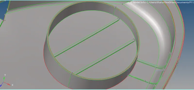
Midsurface of the ribs
- Select the identical ribs and organise them in the single collector
- Create a midline of the ribs which are to be taken for midsurface and using the linestool
- Project the line on the surface using the project tool
- Surface is created between them using the surfaces tool
(lines>midline >select the rib thickness lines >ok)
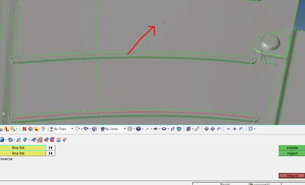
image shows the projection of midline using midline tool
(tools >project>select the line >duplicate >surface normal >create)
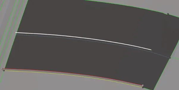
image shows the projection of line on surface
(geometry >surfaces>select the two parallel lines>ok)
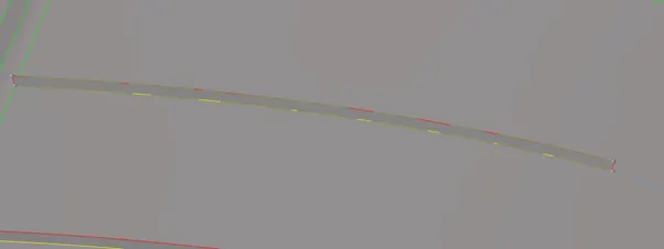
image surface creation in between the lines
Surface trims
In this step the lines are checked for open edges at surface intersection point
(geometry>trim with surface>select>surf 1>surf2>ok)
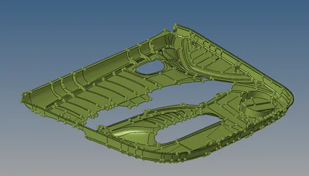
Complete image of the midsurface
Assigning the quality criteria
- Desired quality criteria values are entered for the mesh
- (2d>quality criteria>edit criteria>enter the values >ok)
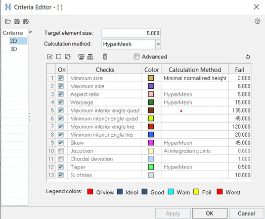
quality criteria table
MESHING
It is the stage where the whole infinte component is divided into the finite number of the elements
(2d>select the surface>automesh >element size 5>ok)
- Remesh: if the elements fails to capture the feature properly they are reconstructed by remeshing the elements.
(2d>autmesh>elements>select the elements>ok)
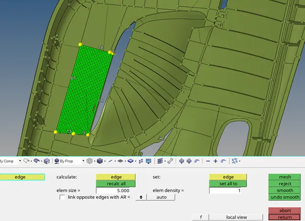
image shows the application of automesh tool
- MESH EDIT TOOLS
- SMOOTH: this is used to change the elemenet size without moving the node point
- Place node: it is used to move the node point for the desired point
- Drag tria : it is used to drag the tria element out of the mesh from the open edge side
- Split: if the element is failing for the max length the element is splitted into two
- Combine tria /; it is used when the two tria are combined they are made into quad by eliminating the line in the quad
- Element optimisation : it alters the position of the elements depending on the adjacent element postions
- Check for the open edges
- Elements are checked for the open edges and are connected in both ways
- Automatically :
(tools>edges>select the elements displayed >preview equivalence>target 0,5>equivalence>ok)
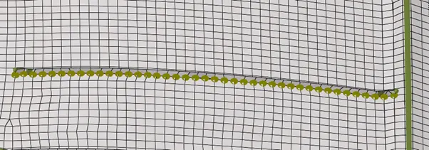
image showing the element equivalence tool
- Manually (replacing the nodes)
(tools>replace select the elements>ok)
- Creating property
1.here , the material is assigned with the property related to the thickness of the component
(create >material >name >rename >1.5)
(create >property >thickness value >rename>1.5)
(1.5>assign>property>1.5>ok)
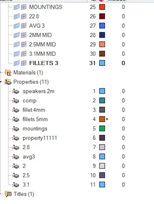
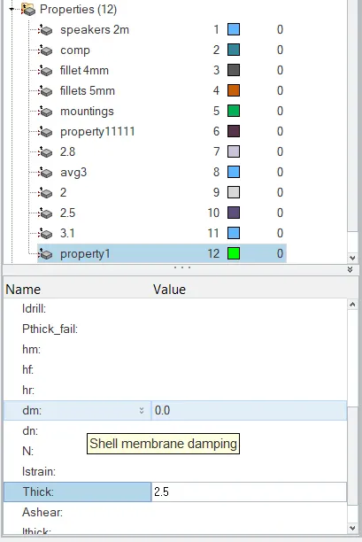
property creation and thickness assining
Image after meshing
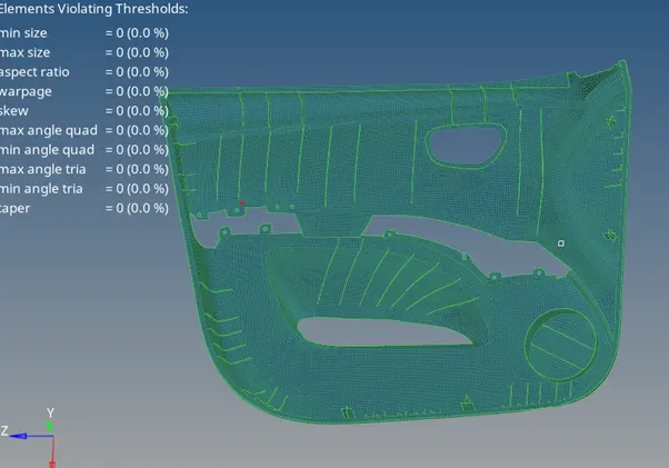
image after completing mesh editing
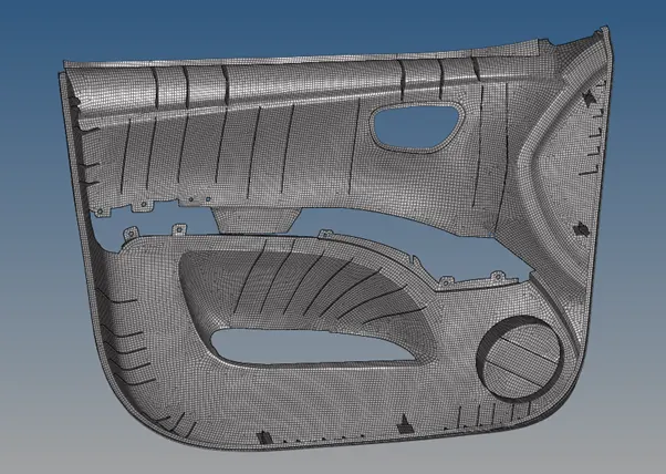
meshed component in property view
outcomes
- Learnt how to create the midsurface for the pladti ccomponent
- Learnt how to mesh the given component under quality critera.
- Learnt how to create the material on basis of thickness and creating the property related to thickness
Result
for the inner door panel midsurface taken and meshed under given quality criteria