Assignment 1-2D Meshing Challenge
AIM:
Mesh the given models under the given 2d mesh quality criteria
Software used :
Hypermesh 2020
Quality criteria :
Target = 5
Min length = 3.5
Max length = 7
Procedure:
Import :
Import the model using the import tool using the data base tools
(import solver desk >select the file >import)
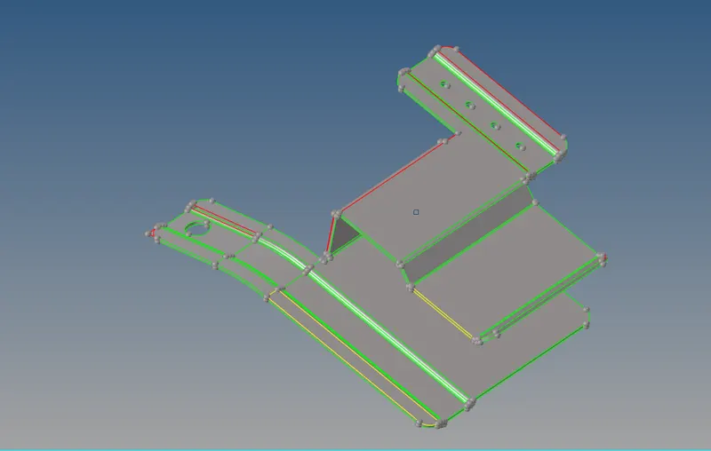
Image shows the component after importing
Check for the open edges in the given model by changing into the topo mode
Sort the open edges in the model using the quick edit tools
(geometry>quick edit tools>toggle the near edges >ok)
Create the surface using the surface tool
(geometry>surface>select the lines>ok)
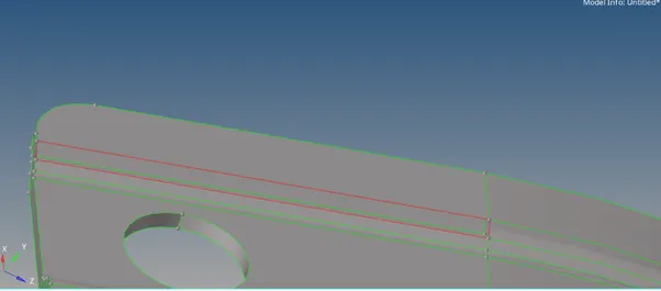
Before surface creation
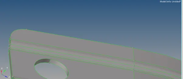
After surface creation
. Measure
Using the measure option check the thickness of the component at the different areas
(geometry>distance>select the points>ok)
Check the diameter of the holes and the holes are closed if the diameter less than 6mm as given
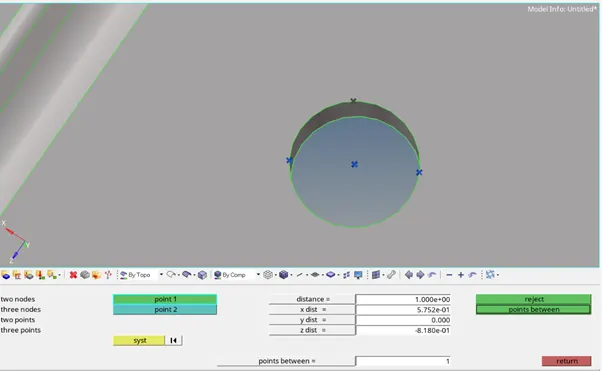
Above fig shows the dia check of circle using the measure tool
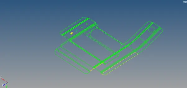
Geometry after complete evalution
Automid surface
Mid surface is taken for the given component using the auto midsurface
(geometry>midsurface>extract offset >skin offset>midsurface>ok)
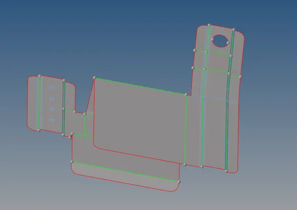
Mid surface of the component
Quality criteria
The quality criteria values are edited and entered
(2d>quality index>edit criteria >enter the values>ok)
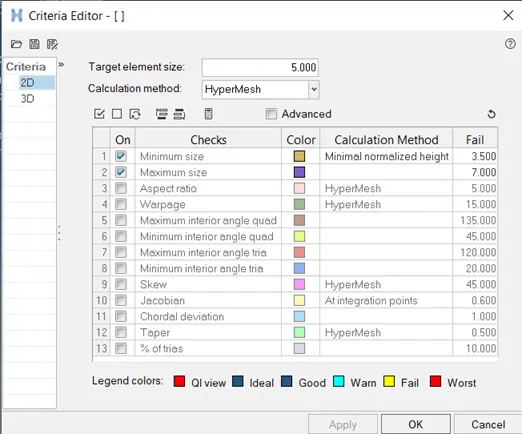
Fig shows the qe table
Meshing
here , the whole component is discretised into finite element size , these elements are used to calculate the stress at the particular areas
select the area mesh the surface as targeted size
(2d>auto mesh>select the uniform area >ok)
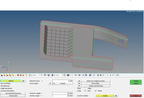
Fig shows the application of the meshing
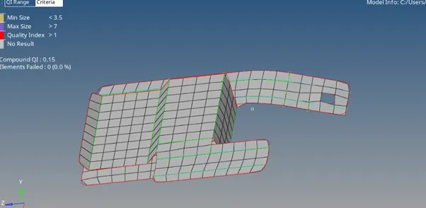
Overall image after meshing
- (right click>create>property>thickness value entered>select the component >assign >property 1)
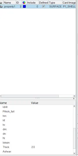
Property table showing the thickness of the material
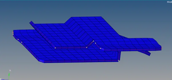
fig in property view
Model 2
similar steps are followed for the part 2 component and meshed under the quality
midsurface image
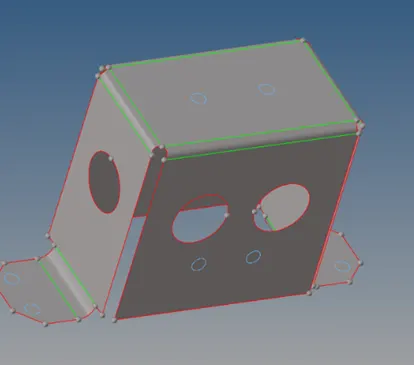
Fig shows the model after mid surface and geometrical evaltion
meshing
Reflect: when the surfaces are same on the opposite side the elements are reflected
(tools>reflect>select the elements to be reflected>axis selection>base point >elements duplication>reflect>ok)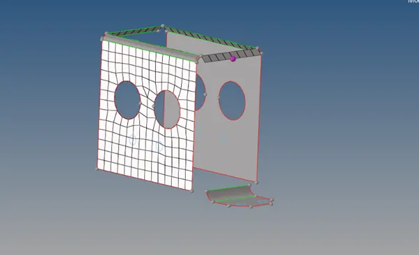
Fig before applying the reflect tool
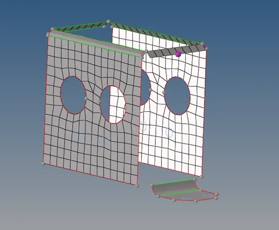
Fig after applying the reflect tool
Edges and equivalence: the element is checked for the tolerance and adjusted for the element connectivity by equivalence.
(tools>edges>select the elements>preview equiavalence>equivalence>find edges>delete edges>ok)
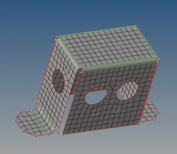
Fig After meshing
property view
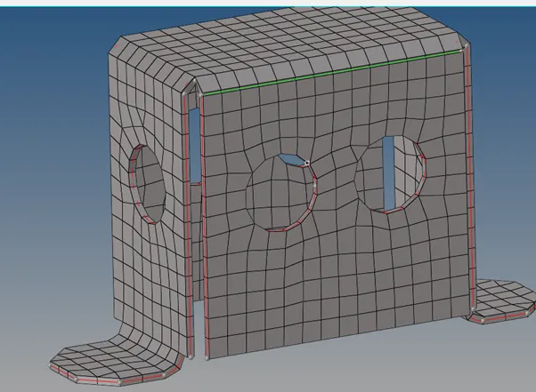
Fig viewed in the property in the property mode
model 3 :
- The model is imported and checked for the open edges
- Surface which would be failed for the minimum lengths are found and toggled
- Creation pf mid line
- Midsurface
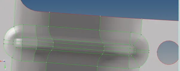
- (geo>lines>midline>select the lines >ok)
- Trim with lines
(geo>surface edit>trim with lines>select the surface >slect the freeline>normal to the surface>ok)
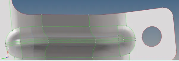
Figure below is the remodulation of the above fig for feature capturing for meshing
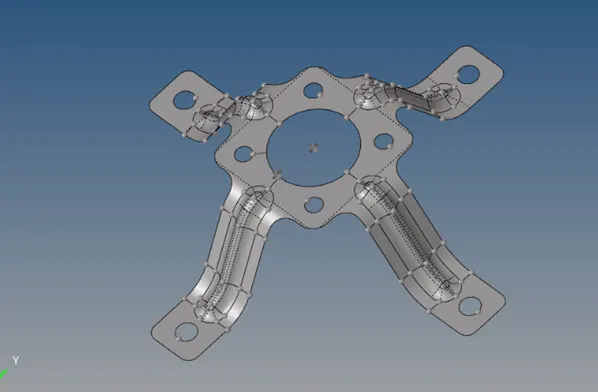
Midsurface image
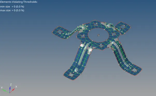
Image after meshing
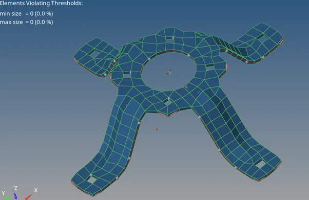
Fig viewed in Property view
Outcomes
- Learnt how to clean the geometry
- Learnt how to take mid surface
- Learnt meshing and mesh editing