Week 8-3D Tetra Meshing Challenge
AIM:
- Model 1: meshing the components using the tetra mesh(3d meshing)
- Model 2: meshing the component using 3d mesh under target element size of 3
- Model 3:meshing the component using the 3d mesh
Software used:
Hypermesh 2020
Procedure
Model 1
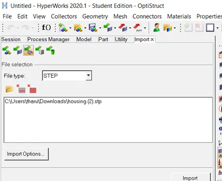
- Import : the given hub model is imported using the gui tool. the cad model is in .stp file
 a
a
above image shows the operation of import tool
- Delete solids : the solids are deleted from the given cad model
- (delete>solids>displayed>ok)
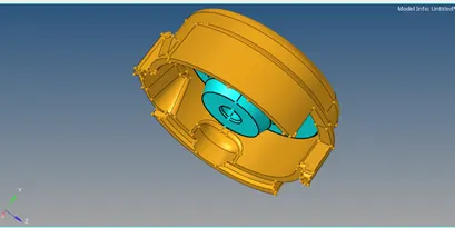
- Geometry check:
The geometry at which the minimum length is possible are evaluated by defeaturing the minimum length
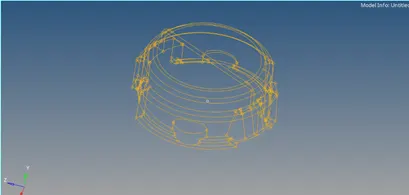
abive image shows the component after clearing the free edges
- Meshing
It is the process in which the infinite nodes are converted into finite equal elements which is further used for the stimulation purposes.
Meshed the component using the 2d element
The meshed component is then adjusted to max and min length by using the clean up tools
Component after meshing(2d)
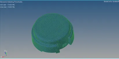
2d meshing image
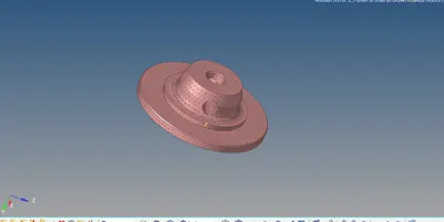
2d meshing of hub
3d meshing (tetra meshing)
Tetrahedral meshing
It is meshing which is generated through 2d meshing in this the 2d element tria is converted into the tetrahedron volume . it is seen in the complex dimension geometries
(3d>tetramesh mesh>input shells>fix comp boundaries>element> displayed>ok)
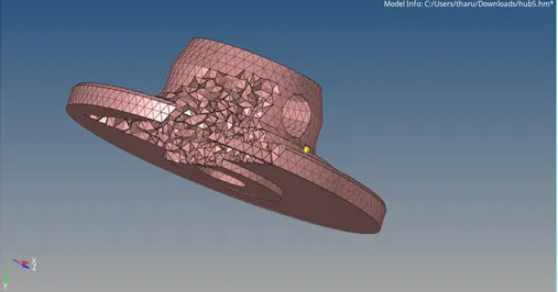
Fig showing the 3d meshing of the hub component
Tet collapse: it is the height of the tetra element . it is the minimum height followed when the element is converted into the 3d element
(tools>check elements>3d tet collapse>save failed)
(mask >retrieve>mask>reverse>tet collapse >ok)
It is sorted in 2 ways
- Manually
- Tetrahedral remesh panel
Tetrahedral panel :here the values minimum , max values of the tetrahedral element and height of the element are constricted so that the remeshing of the elements undergoes element change under the given values
(tetrahedra paramaeters>min length 2>max length 7>tet collapse 0.150>ok)
(tetrahedral remesh >select the tet elements>ok)
It is used when there are more number of the tet collpase elements . it sorts max number of tet collapse elements at once
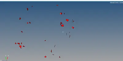
image shows the tet collapse elements (bulk)
Manually
Here, the element failing for the tet collapse is segregated using the mask tool . the shoetest length is checked with in the tetrahedran element and the length is changed until the tet collapse element is evaluated .
Shortest distance is evaluated by translate
(tet elements>measure>two points>shortest distance>translate > translate+)
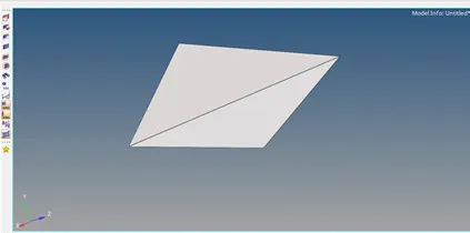
tet collapse (before translation)
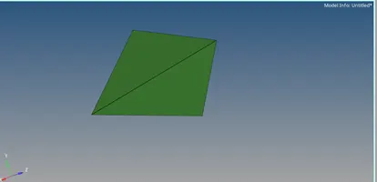
tet collapse after translation
Model 2
Import the model using the import tool
(import>model>ok)
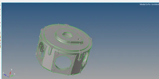
image after importing t
Element size= 3.
- Check for the open edges for the model by viewing in the wire frame mode the open edges are toggled
- (view >browsers>hypermesh>utility>geo>quick tetra>components>components>model>ok)
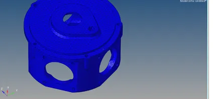
image shows the 3d mesh which is done by quick tetra
Model after tetra meshing

The tet collapse elements statusare shown in fig
Model 3
Element size-4
- (view >browsers>hypermesh>utility>geo>quick tetra>components>components>model>ok)
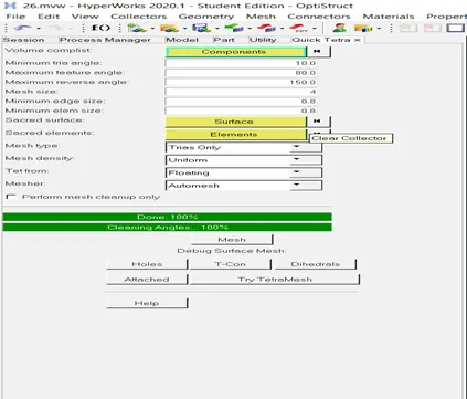
figquick tetra element tab
Model after tetra meshing
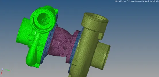
image shows the 3d mesh using quck tetra tab
The tet collapse elements are shown in fig
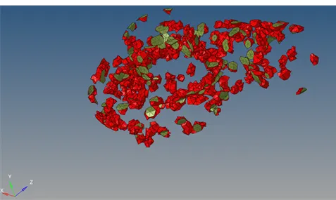
image shows thw tet collpase element included with adjacent element
Organise
Here after the quck tetra mesh the elements are imported to its orginal component using the oraganise tool
(tool>organise>select the elelments >select the destination collector>ok)
Out comes
- learnt how to generate the 3d mesh using the 2d mesh
- learnt how to mesh the component directly using the quick tetra mesh tab
- learnt how to sort out the tet collapse element in the 3d mesh