Week 6-Meshing of Hood Challenge
AIM:
- Extraction of mid surface of the given model
- meshing the component (bonnet of car) under the different quality criteras
SOFTWARE USED :
Hypermesh 2020
THEORY
Hood model is the component used in the car which is used to cover the engine compartment and which gives the good aerodynamic structure for the easy flow of air
It is made of steel as because to resist the high temperature which are produced in the engine compartment
The hood model which also protects the engine compartment from the environmental elements
COMPONENT AND ITS PARTS
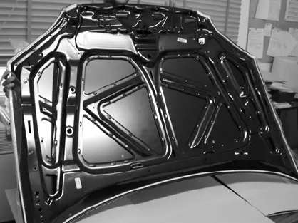
1.OUTER HOO
2.INNER HOOD
3.LATCH (LEFT)
4.LATCH (RIGHT)
QUALITY CRITERIA
|
S.N |
Quality Criteria |
Value |
|
1 |
Aspect Ratio |
5 |
|
2 |
Skewness |
45 |
|
3 |
Warping |
15 |
|
4 |
Taper |
0.5 |
|
5 |
Min. Length |
2 Units |
|
6 |
Max. Length |
8 Units |
|
7 |
Min angle Quad |
45 |
|
8 |
Max angle Quad |
135 |
|
9 |
Min angle Tria |
20 |
|
10 |
Max angle Tria |
120 |
|
10 |
Tria % |
10 |
Procedure
- Import: the given model is imported into the gui using the import tool the model imported is in the .stp file which is saved into the .hm format
- Here , the imported model contains the solids which are to be deleted for the taking the midsurface
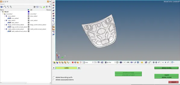
the above fig shows the model imported
3.MIDSURFACE(LATCH)
- The latch geometry is selected by selecting the latch from the utility menu
- Taken midsurface by using the automidsurface tool
- (geometry>automidsurface>select the surface>displayed>ok)
- Near the hole areas the washer element is created to reduce the stress concentration and for good uniform flow of mesh
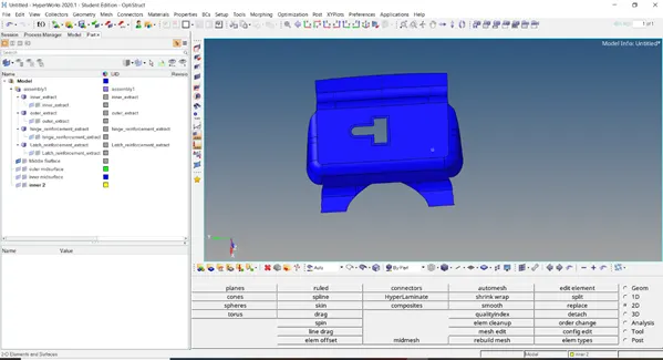
Fig of the latch midsurface
Hinges
- same procedure is followed for the hinges for the mid surface
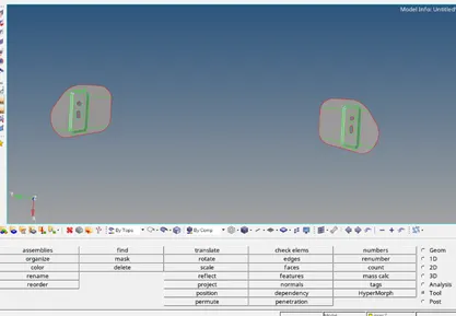
fig of the hinges after taking the mid surface
outer geometry(midsurface)
- midsurface for the outer extract is taken and the geometry clean up is done manually using the quick edit tool
- edge fillet
here as the radius of the geometry is less then the given target element size it is manually adjusted to achieve the given quality conditions
- middle curve :
select the outer edge curves of the fillet through out the geometry and middle curve is generated in between the fillets
(geometry>lines>middle line>select the line 1. Select line 2>ok)
- furtherly it is projected on the surface and splitted into halves
(geometry>quick edit>surface split line>select the surface >node 1> node 2>ok)
- fillet lines are now suppressed using the toggle option
- (geometry>quick edit > toggle>select the line)
- Create a separate component in which the midsurface of the outer geometry is imported
- (utility>create>component.rename>outer geometry>ok)
- (geometry>organise>import>select the surface>displayed>ok)
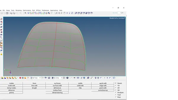
the above image shows the midsurface od outer extract
Inner extract
- Midsurface is taken for the inner extract auto mid surface tool
(geometry >automidsurface >select the surface by attached >ok)
- Geometry clean up:
At the fillet areas the mid surfaces intersection takes places which are deleted and created by the surfaces
(geometry>surfaces>select the surfaces>delete>ok)
- (geometry>surfaces>filler>ok)
- Create the component using the utilty bar and import using the organise
- (create>component>rename>outer layer midsurface>ok
- (geometry>organise>component>displayed>ok)
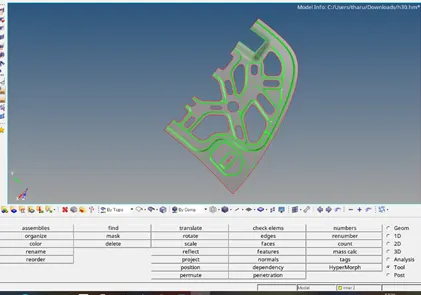
The inner extract symmetry image
Meshing
Here, the mid surface component is meshed , meshing is the process in which the whole component is divided into the equal number of elements . for the stimulation purposes
Latch(meshing)
- the latch surface is selected and mesh is applied using the automesh tool
- (surface>2d>automesh>select the surface >ok)
- Element size is targeted into 5mm the whole element is equally divided into the 5mm
- Quality criteria values are entered in the quality index
- (2d>quality index>qi settings>values to be entered>ok)
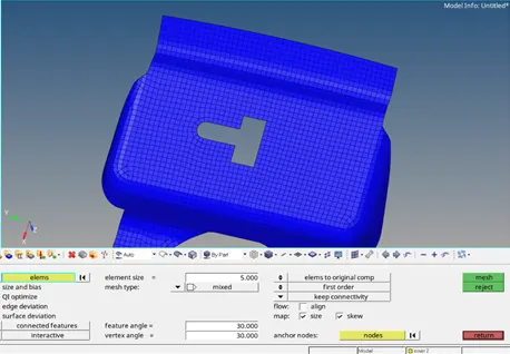
The above fig shows the latch(meshed)
The component meshed to be satisfied the given quality criteria for which the given mesh elements are edited and evaluated using the element clean up tools. While meshing the quads and trias are controlled by adjusting the number of nodes created
Remesh: the areas where the element distribution is unequal the areas are selected by the element criteria selection and remeshed
In this process the number of the trias are reduced and few of the quality failure are sorted out
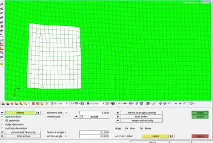
the above image shows the remesh method
Node optimisation :
Few of the warpage and the minimum length quality failures are addressed by the node optimisation where the it adjust the length of the elements by evaluating the sides
place node
By using the place node clean up tool the particular element is selected and adjusted by moving the node of the element
Outer hood (meshing)
Here, the outer extract is selected and the half of the geometry meshed which is after reflected on the other half of the outer geometry
- The component is divided into the larger areas by using the surface split tool for the good mesh flow
- The component is meshed then and mesh is adjusted by using the meshing the elements repeatedtly
- Align node:
at the corners mesh flow is seen in ununiform which is sorted out on to the line by the using the align nodes
select the parent to n1 n2 as reference node and nodes which are to be aligned are selected next
(geometry>node edit>align node> select n1, n2>select the nodes to be aligned >ok)
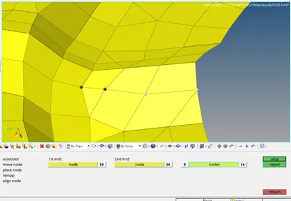
The above image shows the application of align tool
Smooth: it is the element clean up tool which is resolves the quality failures .here , it adjusts the element dimension without the movement in the elements
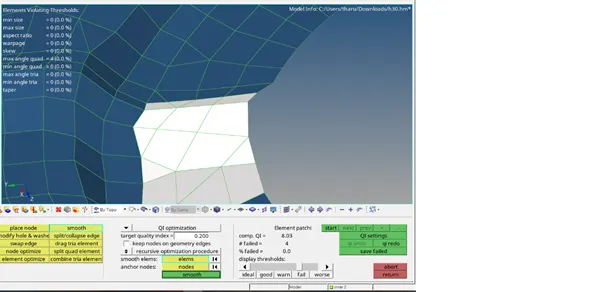
The above image shows the application of smooth tool
Combine: it is also used to join the trias to form the quad elements
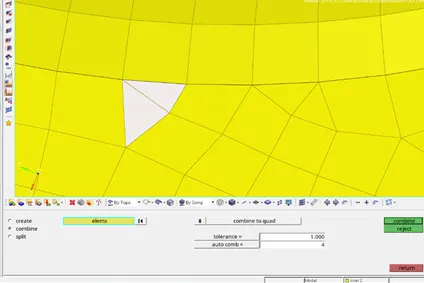
The above image shows the application of combine tool
Reflect the outer extract symmetry
After the element clean up the symmetry is reflected on the other half side using the reflect tool
(tools>reflect>select the elements>by displayed>duplicate>current >y axis >base point> on the geometry>reflect>return)
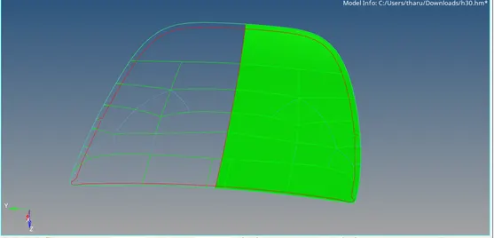
the above image shows the outer hood meshing image before reflecting
Reflecting the surface
(tools>reflect>select the surfaces>by displayed>duplicate>current >y axis >base point> on the geometry>reflect>return)
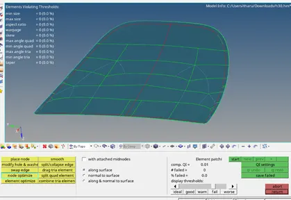
The above image shows the reflected outer hood image included surface
- EDGES
After meshing the elements in few are not addressed accurately which are adjusted by deleting the edges and joining the nodes
After reflecting the outer extract the edge is formed at the mid section which is to be deleted and to be whole component should be made as a whole component
Nodes are addressed in 2 ways
- Manually by replace nodes
- Adjusting the tolerance between the elements
BY TOLERANCE: select the elements deleted the edges and the adjusted by the equivalence
(tools>select the elements >edges>delete edges>preview equivalence>equivalence>ok)
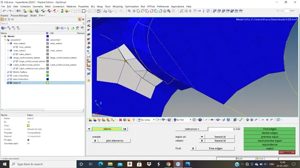
The above fig shows the application of equivalence tool
REPLACE(MANUALLY)
The nodes are selected individually and joined
(geometry>replace>node1>node 2>ok)
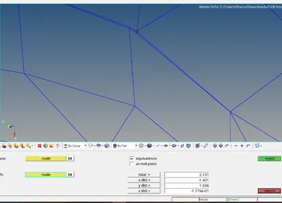
The image shows the application of replace tool
Inner extract(meshing)
the inner extract component is sectioned into two halves where the one half is meshed and reflected on the other side using the reflect tool
1.toggled the small lines which are effecting the meshing
(geo>quivk edit>toggle left click>ok)
2.meshing the component by dividing into larger areas using the quick edit tool
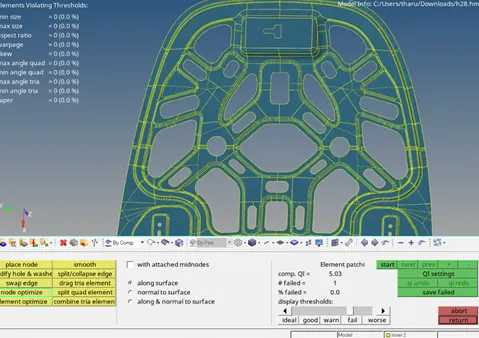
the above image shows the inner hood after meshing and reflecting the symmetry
RESULT
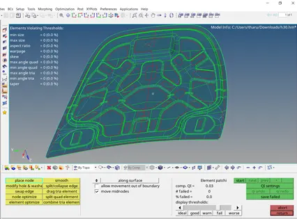
The above image shows the overall image of hood model after meshing
Outcomes
- Learnt how to take the midsurface of the given model
- Learnt how to mesh the given model under given target element size
- Learnt how to element clean using the element edit tools
the model link is enclosed below
https://drive.google.com/file/d/1uTFXSn8XNep7MMil9_BQzs8pIxF6n1Jr/view?usp=drive_web
https://drive.google.com/file/d/1uTFXSn8XNep7MMil9_BQzs8pIxF6n1Jr/view?usp=sharing