Assignment 7-Side Pole Crash Simulation Challenge
AIM:
To perform the stimulation of the car to the rigid body defined and finding the forces at the sections created at different points
OBJECTIVES
- Import the neon 0000.rad file into the database window
- Check for the penetrations
- Creation of the rigidwall
- Creating the type7 interface with the configured term values
- Creation of new COG by adding the mass
- Assigning the velocity to the model in the direction of the rigid wall
- Creation of the cross sections
- Creation of the intrusion point (different areas B pillar , fuel tank)
- Creation and plotting the peak velocity on the driver side door
PROCEDURE
- Import : the model(starter file neon 0000.rad) is imported into using the import tool from the menu bar
(Menu>import>file>neon0000.rad>file >import>ok)
- Units
Check for the units currently running in the model using the cards
(model>cards>begin cards>ok)
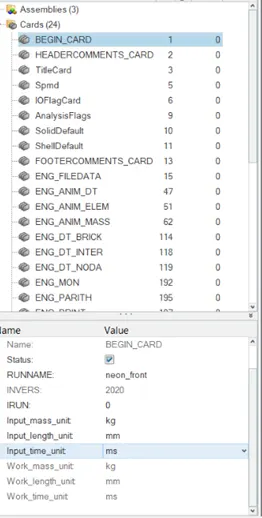
The image shows the engine card showing the units system applied
- Penetrations
The model is checked for the penetrations in the model .which is done to avoid the initial contacts to make the energy calculations ideal
(tools>penetration check>entity>select the whole components by tree selection>check>ok)
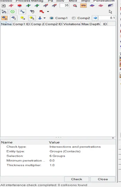
The penetration check tab
- Rigidwall
- The infinite planar rigid wall are created where the whole body is allowed for the deformation
- Dsearch: find the next node with the range limit
- Select diameter = 254
- (solver>create >rigidwall>planar>engineering data>select the peak point of the door >normal>-1 0 0 >Dsearch =400>friction 0.1)
- The frictional force is considered for accurate calculations of the forces .
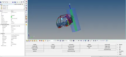
the above image shows the rigid wall (pole)
- COG(centre of gravity )
- For the given model the targeted mass is 700 kg which is gained by adding the addional mass
- Check for the initial cog
(tools>mass details >cog , mass details>cog >ok)
3.add mass
(create >admass>rename>cog>entity>select the nodes>mass value >ok)
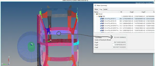
The above image shows the cog after adding the mass
- INiTIAL VELOCITY
- The speed of the car is defined with which the body gets interacted with the rigid body
- Velocity given = 35MPH=15.64mm/ms in the x direction
- (solver>create >boundary conditions>INIVEl>entity >select the all components>nodes>0 15.64 0 0>ok
- Check for the direction of the arrow created
- ENGINE CARDS
- Here , the engine cards are assigned according to the stimulation run
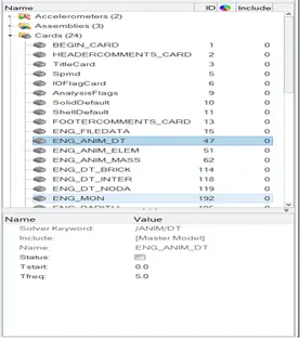
- ENGINEANIM/DT
(Model>Cards.>engine/dt>T freq =5)
- ENG RUN
- (Model>cards>run>Tstop=80)
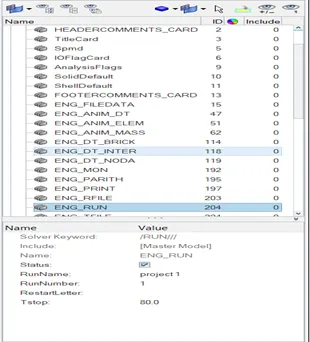
The above image shows he run data limit
- INTERFACE
- Type 7 interface is created with the specific input variables
- Istff=4
- Idel=2
- Igap=2
- Inact=6
- Stiff=1000
- Gap min=0.5
- Frict=0.2
- I form=2 stiffness
I gap : it defines the size of the gap between the components .it also considers the variable gap
Gap min: it the minimum gap between the parts where the stimulation gets activated. When the load applied breaks the minimum bridge value. Elements starts deformation
I stiffness: it is the stiffness between the master and the slave nodes. It shows the stiffness effected in the spring in the particular interface
I form :sliding forces in the elements due to the viscous or the frictional forces
ST min: it is minimum stiffness used in the interface .this is recommended when the contact elements are to smooth . and recommended when the elements deformation is high then the recommended value
I del : decides the behaviour master and slave nodes when the elements corresponding gets deleted
In act: it is used to check and sort out the initial penetration in the elements .it also used additional energy to drag the penetrated element which is accounted in the energy errors
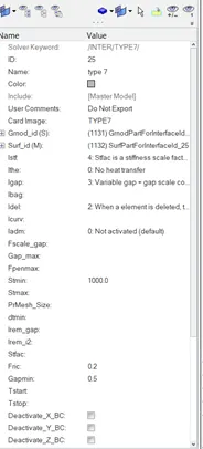
type 7 interface card image
- CROSS-SECTIONS
- These are the areas selected in the model where the forces passing through this are calculated and noted in the graphs
- (solver>create>sections)
- (solver>create>frame>select the centre>select the x point>select the another node in the direction of the xy node)
- (select the cross section created>rename>select the nodes>frame >select the created frame by mouse>entity>create>elements>select the cross section elements >iframe=12.
- Repeat the 2 for the creation of the other sections
- (model>create>output blocks>renamecross sections>select all>ok)
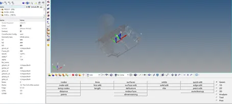
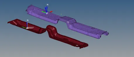
The above image show the cross sectional areas
- INTRUSIONS
Here, nodes are created at 2 nodes where the displacement of elements are noted down checked weather the crash occurred in the occupant area in minimal or maximum.
(create >intrusions>select the nodes >frame>select the local skew>ok)
(create>output block>entity>intusions>ok)
- PEAK VELOCITY
Peak velocity is used to determine the velocity on the node . in the real time it shows the force effect on the driver compartment .
(R click>create>th>node>select the node>select the skew >ok)
Model checker
Here , the model is checked for the errors using the model checker if the model checker is passed then stimulation should be started using the radios
(tools>model checker>run)
Analysis
First check for the dry run if the errors found in the stimulation are 0
Go for the real time running of the model
(analysis >radioss>include connectors>-nt 4 >save as>project20000.rad >ok)
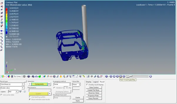
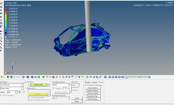
image shows the von mises stress values
Output
Energy Graphs
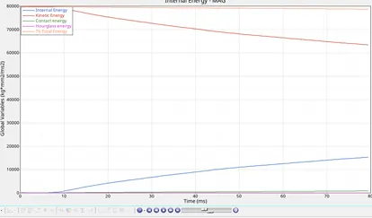
image shows the hyper graph for the energies
From the graphs it shows the kinetic energy goes on decreasing as the velocity decreases the KE also decreases and the internal energy goes on increases .internal energy is something which are the shocks are the jerks that absorbed by the occupant .
Total energy is the summation of the contact energy, hourglass energy , kinetic energy
Cross sections
Cross sections are used to display the forces passing through the selected nodes . chassis frames were selected . when the vehicle is struck to the pole .the frame near to the pole area is deformed first . and the deformation is also dependent on the type material and its thickness
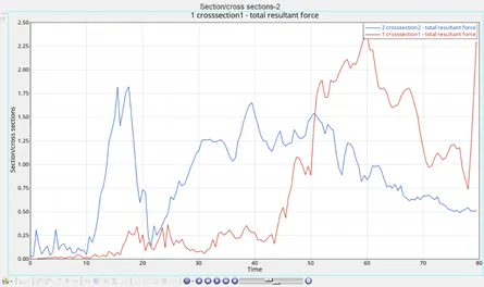
image shows the crossections graphs for 2 frames
When the vehicle is struct the pole the deformation in the centre frame is seen initially and force is found max F= 1.75 at T=15
After the certain length deformed the force is distributed to the cross section 2 and the maximum deformation is found max F = 2.50 at T=60
INTRUSIONS
Intrusions are used to record the displacement occurred with the elements when the deformation is started
A pillar
maximum displacement or intrusion is seen this case as elements are very near to the Dsearch range it is the first component effected when the body is made in contact with the rigid wall
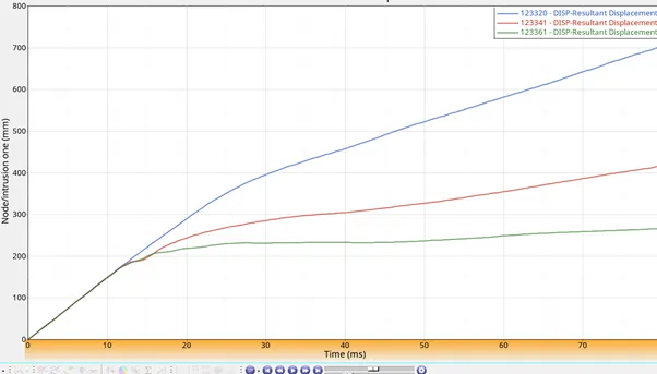
above image shows the displacement curves for A ,B pillars and fuel tank curves
maximum intrusion found in the hinge pillar 700mm
B pillar
compared to the a pillar the intrusion is slightly less as the elements experience less force . here , the displacement experienced by these component is the out put force from the A pillar .
B pillar component is also found slightly rigid compared to the A pillar
Maximum intrusion found on the B Pillar 405mm
Fuel tank
As the fuel tank elements are found too far from the rigid wall force the force experienced is less and the fuel tank is mounted in such a way that it is sipported on the 4 bars which tends to develop the resistive force to cut the displacement
Maximum intrusion is found at point 280mm
For the A pillar hinge the intrusion is reduced by either changing the material properties of the shell elements by distributing the forces experienced to many rigid connections
Peak velocity
Peak velocity is used to show the displacement occurred on the driver compartment by selecting the node on the door frame
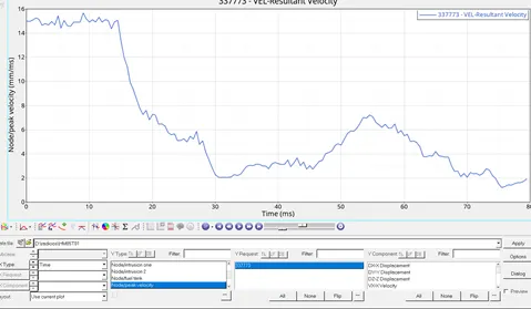
image shows the peak velocity for the point (door side)
From the graph we can observe that initially speed is maintained up to 15ms until it is hitted to the wall .once when it is struck the velocity fluctuates velocity increases and when the KE decreases the velocity will also gets decreased .
Outcomes
-
- learnt how to create the rigid wall for the given type of the anlaysis .
- learnt how to change the COG of the material
- learnt how to create the sections for the at different areas and found the force absorbed in that sectionsat diffrent areas
- learnt how to find the peak velocity on the driver compartment area
- learnt how to perform the penetration for the whole model
- learnt how to perform the model checks
- https://drive.google.com/file/d/1LFHaq0EODttUpTp4LYgPt8voAXZYUCDF/view?usp=sharing