Project 2
AIM: To take the mid surface r the given suspension model and check geometric errors and meshing the given component using the trias and quads at necessary areas under given quality criteria
Giving the different connections at the required areas
SOFTWARE USED
ANSA v19.1.5
THEORY
Suspension is the part of the vehicle which absorbs the vibrations occurred when the vehicle is subjected to jerks
It distrubutes the inertia which is occurred on the irregular load it bears half the weight of the vehicle it the link rods connected to it helps in the easy moment of the steering
There are different types of suspensions system
- Macphearson
- Double wishbone
The given model comes under the macphearson on which the steering knuckle is connected to the suspension system macphearson is a modern day evolution .
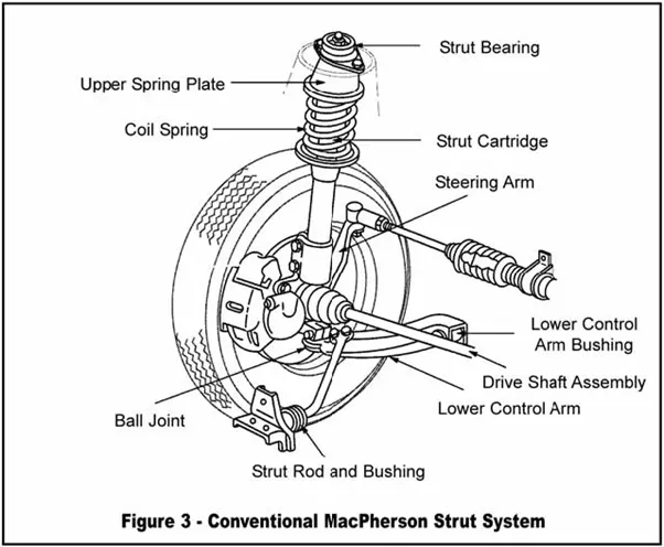
Given model includes parts named
- Link rod
- Brake disc
- Brake kit
- Suspension spring
- Steering swag bar
- Lower bed
- Tyre
- Alloywheel
- Wheel hub
- Strut assembly
- Ball joint
- Toe rod etc…
Procedure
- Initially the given cad model is imported into the ansa and saved as .ANSA as an extension file
- Importing the geometry includes a geometrical errors which are to be evaluated
- Apply topo for the model where the single and double cons are converted to the double and the triple cons
The topo module>faces>topo>selection of the geometry>ok
- The whole geometry is to be adjusted to a specified length for the proper visibility the geometrical model
Mesh>parameters>length >selection of the whole geometry>length=1>ok
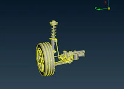
Figure showing the given cad model
ASSIGN PIDS
- Pids are to be assigned for the individual parts and the names are given
- (topo>faces>set pid>right click >create>new>pshell>edit the thickness>ok)
- Assigned pids are enclosed
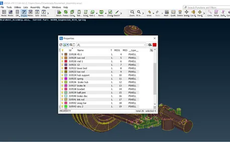
Fig showing the assigned pids
Geometry check up
- Selection of the individual pids are selected and the geometrical check is done
- (checks>geometry>ok>execute>errors>auto fix>ok
- Errors which are not solved in the auto fix are sorted out manually
- Triples cons and the intersection edges
- Triple cons rectification: (select the con>topo>faces>release>topo>ok)
- Single cons are converted into the double by the paste option
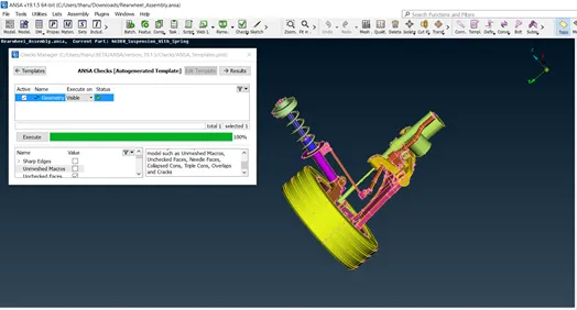
Fig represent the complete geometry check up
MIDSURFACE OF THE BRACKET AND THE SUSPENSION PART
- Midsurface : offset the given bracket into the half the geometry
- (topo>faces>offset>model sel>value =3/2>ok)
Mid surfaces for the bracket and the suspension part are enclosed
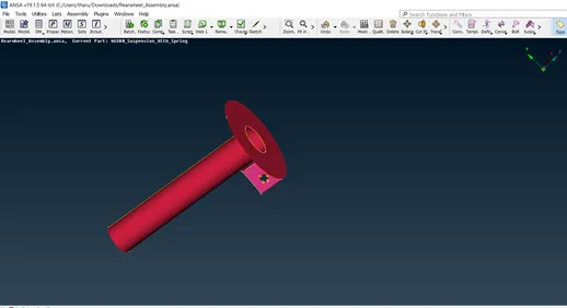
fig showing the mid surface of the bracket and the sus asm
QUALITY CRITERIA
- Mesh quality and the length of min and max length and the mixed type is selected
- (quality criteria >enter the values>apply>ok)
- Quality criteria for Mixed elements (For Midsurface only):
|
S.No |
Quality Criteria |
Value |
|
|
|
|
|
|
|
1 |
Target/Average length |
4 |
||||||
|
2 |
Minimum Length |
2 |
||||||
|
3 |
Maximum Length |
6 |
||||||
|
4 |
Aspect |
3 |
||||||
|
5 |
Warpage |
15 |
||||||
|
6 |
Skewness |
45 |
||||||
|
7 |
Jacobian |
0.7 |
||||||
|
8 |
Minimum Quad Angle |
45 |
||||||
|
9 |
Maximum Quad Angle |
135 |
||||||
|
10 |
Minimum Tria Angle |
30 |
||||||
|
11 |
Maximum Tria Angle |
120 |
MESHING
. Applied mesh for the given model using the spot meshing where the mesh type is selected as the mixed type
(mesh>mesh generation>spot meshing >select of geo>ok)
- Selection of the area is to be done and the meshing is applied and the offset elements are created are rectified by the reconstruct, smooth, split tools
- (mesh>shell mesh>reconstruct >select the offset elements>apply>ok)
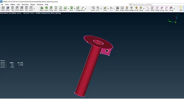
Fig represents the meshing of the bracket and the sus asm
- The area where the thickness is less than 6mm the solid mesh is to be generated the meshing in this case is done by the trias and the ortho trias
Quality criteria
- length is considered Average as 4
Quality of the parts like link rod , ball joint are mentioned below
- Minimum length =2
- Max length =6
- Tet collapse (shell) =0.2
- Skewness =45
- MESHING
- Apply the tria mesh for the child parts and the generated offset elements are sorted by the reconstruct and split option
- The offset elements which are for the max length is sorted by the split tool
- Figures of the meshed parts are enclosed below
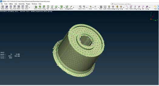
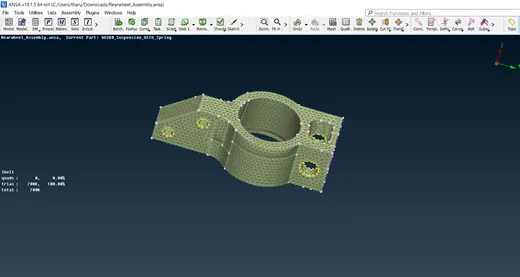
Fig showa the tria mesh of support
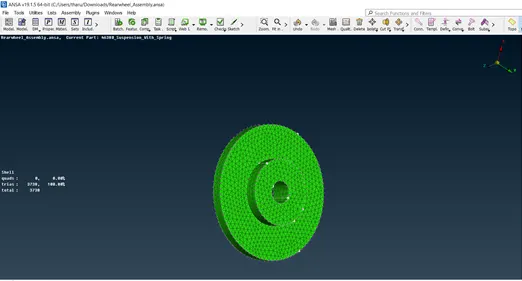
fig shows the tria mesh of the mech strut lower
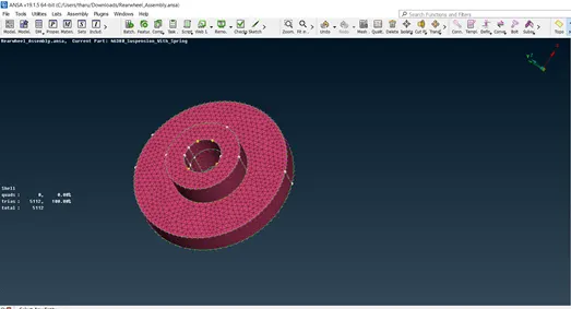
fig shows the tria mesh of the lower mount strut
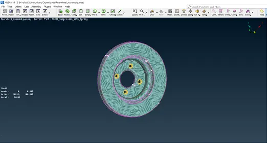
Fig shows the tria mesh of the brake disc
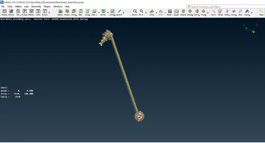
Fig shows the tria mesh of the link rod
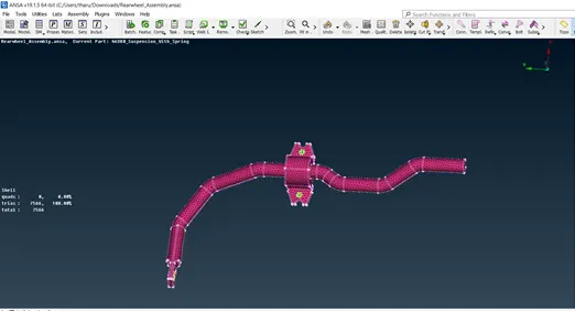
fig represents the tria mesh for the swag bar
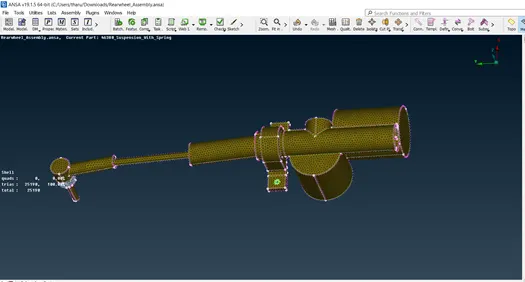
Fig shows the tria mesh for the tie rod
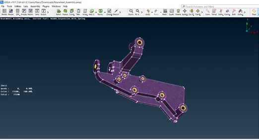
fig shows the tria mesh representation of the lower support
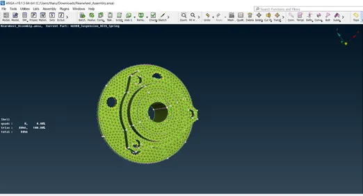
Fig shows the tria mesh for the hub
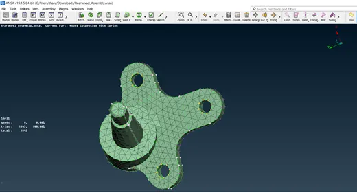
fig shows the tria mesh for the ball joint
Fig shows the tria mesh for the alloy wheel
Fig represents the tria mesh for the tyre
NOTE: more elimination of the offset elements at the complex area leads to the change in geometry so that is the reason offset elements are left over
GENERATION OF THE VOLUME MESH
- Model which are underwent through the tria mesh are considered here
- Changing into the vmesh deck
- Selection of the fea model and generate the pid element which is to be meshed
- Define>manual>select the child part >create the pid >right click >new>psolid>give the name<ok
- Select the tetra rapid and apply over the model
- (vmesh>unstructured mesh>tetrarapid>ok)
- Thus the volume mesh is generated over the model
- For the confirmation go to the list check the status which is changed to the meshed and the type ia also seen in the list
- (vmesh>list>check the status >ok)
Offset elements
Tetcollapse: after the generation of the volume mesh tet collapse elements are seen which are to be sorted by addressing them individually
Selection of the tetcollapse and isolate them and sorted out by the mv free tool
- Select the tetcollapse element choose the point and move according until the tet collapse is eliminated
- (check the offset elements>right click >show only> address the tet collapse element>isolate>mesh>grids>mv free>select the node>ok)
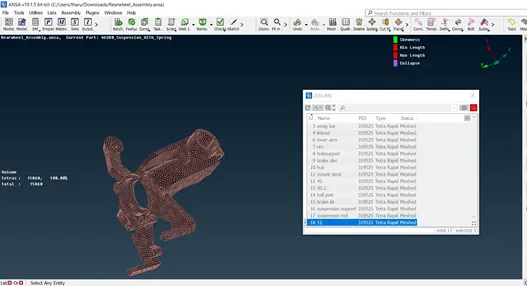
Fig shows the volume mesh for the part
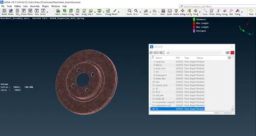
Fig shows the volume mesh fo the brake disc
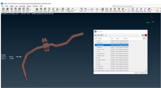
Fig shows the volume mesh of the swag bar
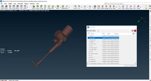
Fig represents the volume mesh for the tie rod
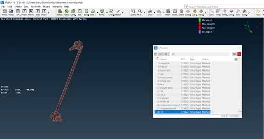
fig shows the volume mesh for the link rod
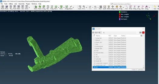
Fig shows the volume mesh if lower support
Quality criteria for tyre and rim
AVG LENGTH =6
MINIMUM LENGTH =5
MAX LENGTH =10
TET COLLAPSE =0.2
SKEWNESS =45
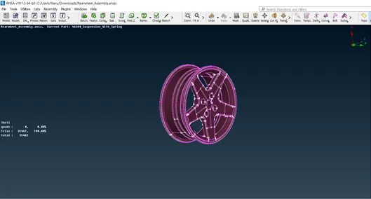
fig shows the tria mesh of the rim
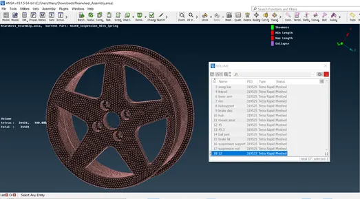
Fig shows the volume mesh of rim
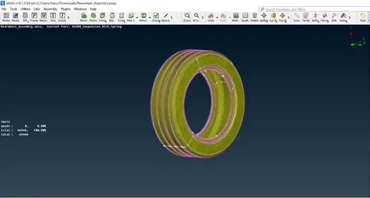
Fig shows the mesh for the tyre
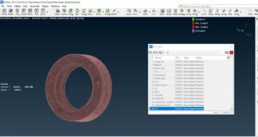
fig volume mesh of the tyre
Connections
- In order to rigid movement of the parts they are fixed by the connections
- Connections used here are RBE2 2 NODE, MANY NODE, SEAM WELD CONNECTION, CBAR CONNECTION
Connection between the bracket and the suspension asm
- Connection done is seam weld connection create the curve and converted into the seam weld and weld is created between the two layers by shell overlap
- Overlap shell type is used when the welded surfaces are in parallel to each other
- (select the line>topo>curves>cons to curve>select the line >convert>seam weld>click on the line >connection>type>overlap shell>p1>modify>select the bracket geometry>p2>modify>select the sus asm>overlapshell>search distance>30>width>3>step length>5>
Weld element>shift+?>created seam weld connection pid > realize>ok)
Seam weld connection is enclosed below
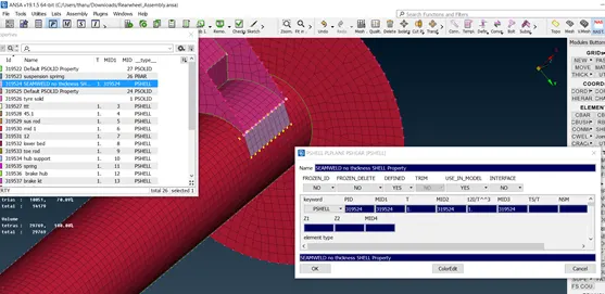
Fig above shows the seam weld connection
Representation of the spring in 1 d element and generating the c bar connection
. As the spring is subjected to the loads it translates in up and down. so the connection is done such a way when the load applied it should not vary its shape .the connection used here is cbar type
Representation of spring
- Select the spring and isolate the geometry
- (mesh>curves>middle>ok>remove the geometry>connect >multi>ok)
- thus the curves created are connected and converted into the single entity
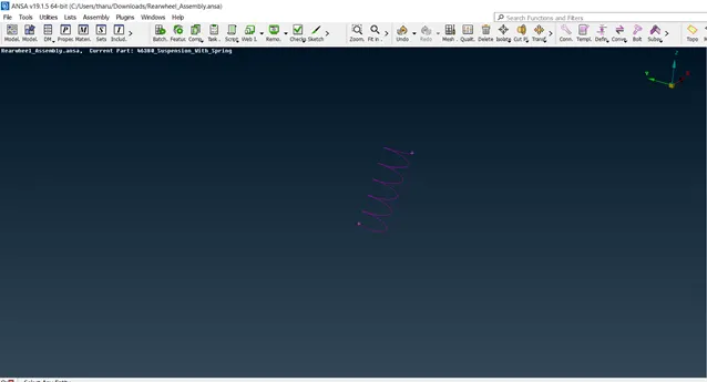
Fig above shows the representation of spring in 1d elemnt using the curve
CBAR CONNECTION
(Select the curve>nastran>Cbar>on curve>ok>element size>3>ok>pid of pbar>enter the name>area>shift+?>area>r=5>ok>connection is shown
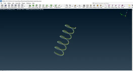
Fig above shows the c bar connection
Conversion into the solid
- (quality criteria >tick the material cross section>as solids.)
thus the solid representation is done
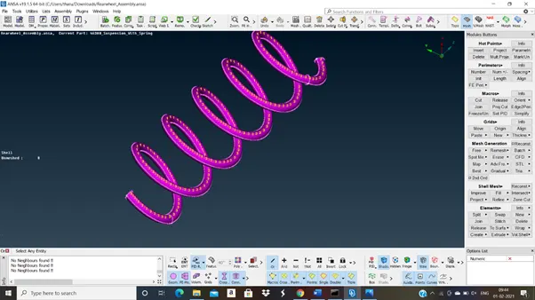
Fig above shows the cbar connection in solid mode
CONNECTION BETWEEN THE SHAFT AND THE HOLE AND THE BOLTS
The connection used in this case is RBE2 2 node and many node
RBE2: This type of connection is mainly used to represents the bolts , amd also used to generate the connection between two mating parts using the slave and masters nodes
This is also used in the conmass applications
Connection using the RBE2 many it is used to represent the rigid connection with in the single geometry .master node is created at the centre all the selected nodes
Fig
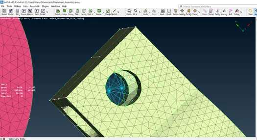
fig above shoes the RBE2 MANY node connection
RBE2 TWO NODE
This is used to represent the connection between the bolts and the holes and the connection near the 2 mating shafts
BOLT REPRESENTATION
(RBE2>SELECT THE TWO MASTER NODES OF ADJACENT SIDES>OK>ADRESS THE GEOMTRY IN THE PID>OK)
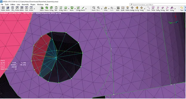
In the above fig yellow line represent the two node connecion
CONNECTION BETWEEN THE SHAFT AND THE HOLE
(SELECT THE NODE FROM SHAFT>SELECT THE NODE FROM SHAFT>OK> SELECT THE GEOMETRY>OK)
FIG
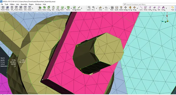
in the above fig shaft connection is shown in yellow lines
TRANSFORM
The overall geometry is mirrored in opposite side it is used only when the mirrored geometry is exactly same on opposite side
It saves time and evaluate the geometry quick
(transform>copy>symmetry>3 point selection>ok
thus the whole geometry is mirrored
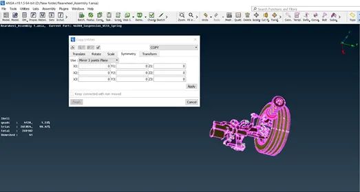
In the above the application of the transform tool is seen
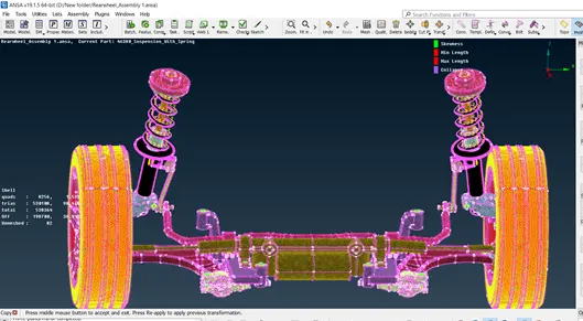
The above fig shows the copy of geometry in opposite side
RESULT
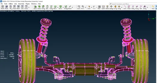
The above image shows the complete pre processed suspenion
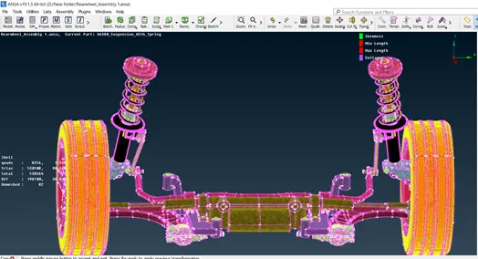
The image shows the geometry in hidden elements which includes offset elements
LEARNING OUTCOMES
Learnt how to check geometrical errors manually , take mid surface apply meshing, apply according to the quality criterias, apply tria mesh and generating the volume mesh
Learnt how to deploy the connection using the Nastran deck using tools rbe2 cbar etc…,
CONCLUSION
Thus the preprocessing of the given cad model is done using the ansa using different decks namely topo, mesh, vmesh , Nastran decks
Link for the download of model
https://drive.google.com/file/d/1aSYUuZia5PxsNJa1YMkjFGpNN-epAE4I/view?usp=sharinghttps://drive.google.com/file/d/1aSYUuZia5PxsNJa1YMkjFGpNN-epAE4I/view?usp=sharing