Week 12:Project 2-Meshing of Rear Wheel Holder challenge
AIM:
The given floor model is meshed under the given 2d mesh quality criteria
Software used :
Hypermesh 2020
Quality criteria
|
S.N |
Quality Criteria |
Value |
|
1 |
Aspect Ratio |
5 |
|
2 |
Skewness |
45 |
|
3 |
Warping |
15 |
|
4 |
Taper |
0.5 |
|
5 |
Min. Length |
2 Units |
|
6 |
Max. Length |
8 Units |
|
7 |
Min angle Quad |
45 |
|
8 |
Max angle Quad |
135 |
|
9 |
Min angle Tria |
20 |
|
10 |
Max angle Tria |
120 |
|
10 |
Tria % |
10 |
Procedure:
Import : the model is imported into the hypermesh using the import tool
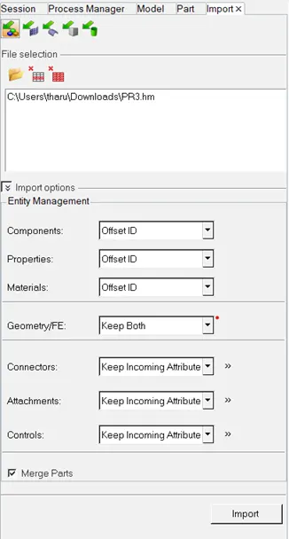
Above image shows the import function application
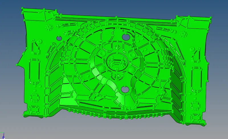
image shows the model after importing into the data base
Check for the solids : the given model is checked for the solids
Measure : the model thickness is measured for the thickness using the measure tool . by measuring the thickness at various places confirmed it as an uniform thickness model
(geometry>distance>two points>select points>ok)
Auto midsurface : as the component is having the uniform thickness auto mid surface is taken for the component and the it is renamed as midsurface
- (geometry>automidsurface>select the surface>displayed>ok)

image shows the automidsurface tool application
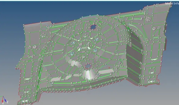
Image shows component after taking midsurface(auto)
Geometry checks :
In this step the glitches found after the midsurface are evaluated by using the quaick edit tools
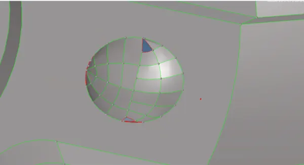
Above image shows the geometry glitch formed after midsurface
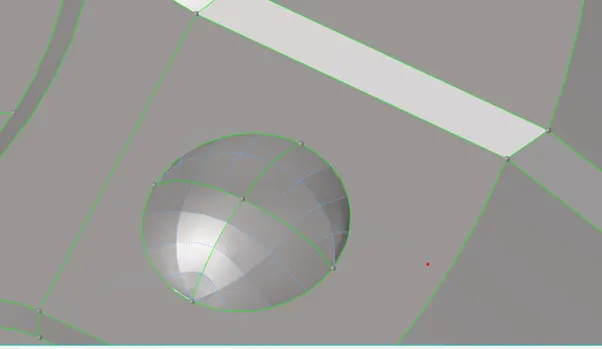
After sorting out the geometry glitch
Meshing :
Meshing is the condition where the whole component is subtracted into the finite elements the component is divided into the equal element size
the above image shows the component after meshing
- Quality criteria : the given quality criteria conditions are entered using the edit criteria
- (2d>editcriteria>enter values>apply>ok)
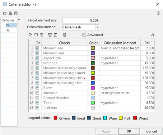
the above image shows the quality criteria values entered
- Meshing : the area is selected for meshing applied mesh ,mesh is applied in such a way that the max number of quads are created over the trias .
- (surface>2d>automesh>select the surface >ok)
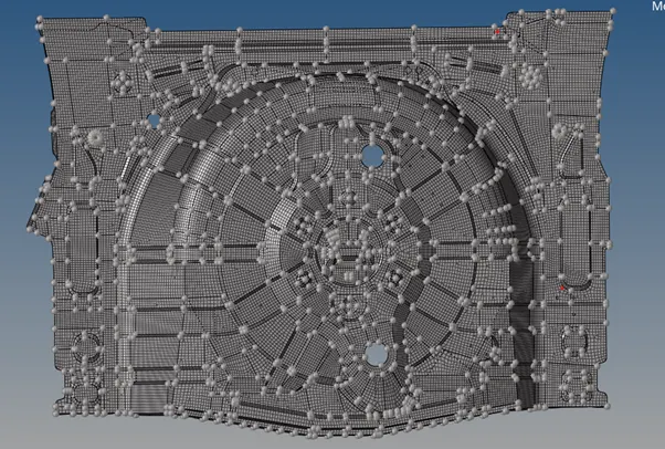
- The above image shows the component after meshing
The trias concentration is reduced by remeshing the elements
- The applied mesh is altered for many changes as to achieve the mesh criteria using the mesh edit tools like smooth , align node , element optmisation
Minimum length failure :
In some areas the meshing element failure occurs at the area where the feature length is less then the minimum length
- Edges
Meshing is checked for the connectivity through out the surface if found any open edges they are sorted out by element equivalence and replace node functions
(tools>select the elements >edges>delete edges>preview equivalence>equivalence>ok)
if the elemenent edge connections are beyond the equivalence point they are adjusted manually using the replace tool
(tool>replace select the nodes >ok)
- Delete element duplicates
The elements are checked for the duplicate elements and are deleted if found any they are deleted
(tool>check elements>duplicates >select the elements displayed>savefailed>delete >retrive>ok)
- Property creation
(create>propertty>rename>t0.8>assign>property>ok)
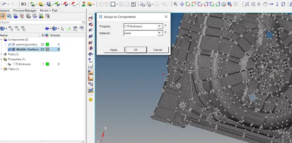
The above image shows how to assign the property to the component
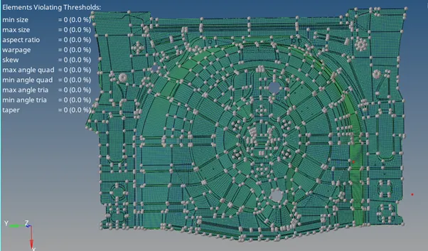
The above image shows the component after sorting out all the mesh quality
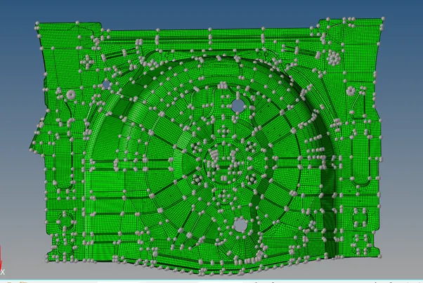
The above image shows the component which is view by the property assigned
outcomes
- Learnt how to take midsurface
- Learnt how to mesh the component under the given quality criteria
- Learnt how to assign the property for the model .
Result
Taken midsurface for the given model and meshed the component as according to the quality criteria