Assignment 6-Frontal Crash Simulation Challenge
AIM:
To perform the stimulation of the car to the rigid body defined and finding the forces at the sections created at different points
OBJECTIVES
- Import the neon 0000.rad file into the database window
- Check for the penetrations
- Creation of the rigidwall
- Creating the type7 interface with the configured term values
- Creation of new COG by adding the mass
- Assigning the velocity to the model in the direction of the rigid wall
- Creation of the rigid wall
- Creation of the cross sections
- Creation of the accelerometers
- Creation of the intrusion point
PROCEDURE
- Import : the model(starter file neon 0000.rad) is imported into using the import tool from the menu bar
(Menu>import>file>neon0000.rad>file >import>ok)
- Units
Check for the units currently running in the model using the cards
(model>cards>begin cards>ok)
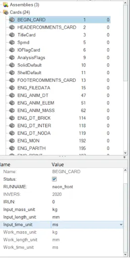
The image shows the engine card showing the units system applied
- Penetrations
The model is checked for the penetrations in the model .which is done to avoid the initial contacts to make the energy calculations ideal
(tools>penetration check>entity>select the whole components by tree selection>check>ok)
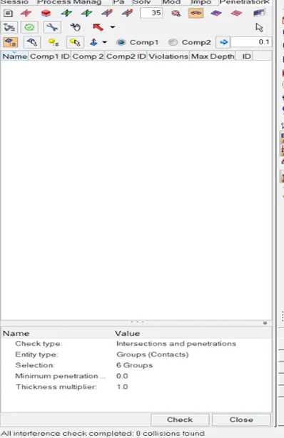
The penetration check tab
- Rigidwall
- The infinite planar rigid wall are created where the whole body is allowed for the deformation
- Dsearch: find the next node with the range limit
- (solver>create >rigidwall>planar>engineering data>select the peak point of the bumper>normal>-1 0 0 >Dsearch =1000>friction 0.1)
- The frictional force is considered for accurate calculations of the forces .
- COG(centre of gravity )
- For the given model the targeted mass is 700 kg which is gained by adding the addional mass
- Check for the initial cog
(tools>mass details >cog , mass details>cog >ok)
3.add mass
(create >admass>rename>cog>entity>select the nodes>mass value >ok)
4.repeat the step 2
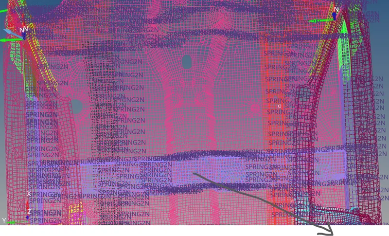
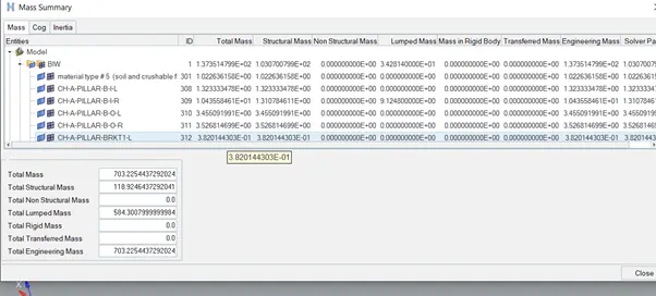
The above image shows the cog after adding the mass
- INiTIAL VELOCITY
- The speed of the car is defined with which the body gets interacted with the rigid body
- Velocity given = 35MPH=15.64mm/ms in the x direction
- (solver>create >boundary conditions>INIVEl>entity >select the all components>nodes>15.64 0 0>ok
- Check for the direction of the arrow created
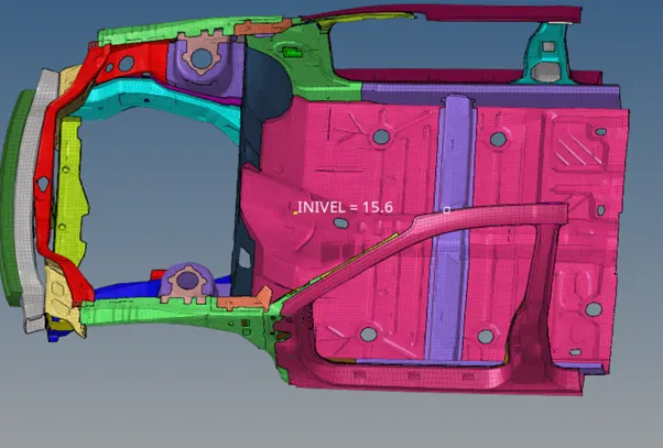
- the image shows the initial velocity
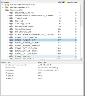
- ENGINE CARDS
- Here , the engine cards are assigned according to the stimulation run
- ENGINEANIM/DT
(Model>Cards.>engine/dt>T freq =5)
- ENG RUN
- (Model>cards>run>Tstop=80)
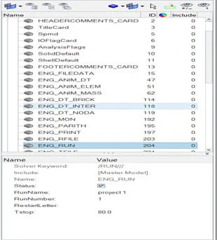
The above image shows he run data limit
- INTERFACE
- Type 7 interface is created with the specific input variables
- Istff=4
- Idel=2
- Igap=2
- Inact=6
- Stiff=1000
- Gap min=0.5
- Frict=0.2
- I form=2 stiffness
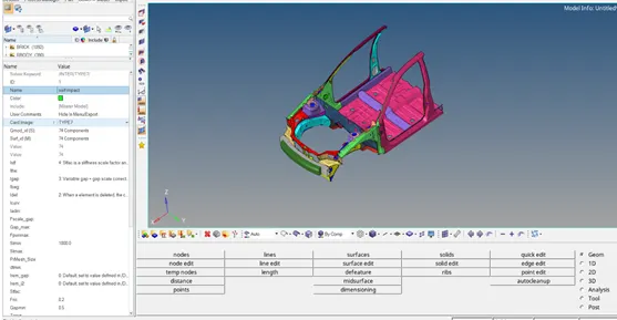
The above image shows the type 7 interface
- CROSS-SECTIONS
- These are the areas selected in the model where the forces passing through this are calculated and noted in the graphs
- (solver>create>sections)
- (solver>create>frame>select the centre>select the x point>select the another node in the direction of the xy node)
- (select the cross section created>rename>select the nodes>frame >select the created frame by mouse>entity>create>elements>select the cross section elements >iframe=12.
- Repeat the 2,3,4 for the creation of the other sections
- (model>create>output blocks>renamecross sections>select all>ok)
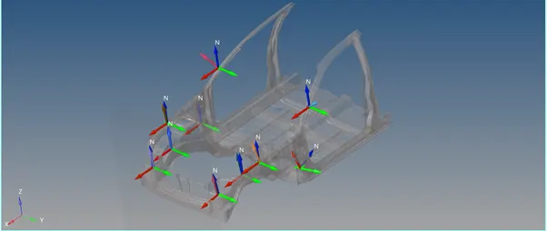
The above image show the cross sectional areas
- ACCELEROMETERS
These are used to check the change in velocity , here the nodes are created on the B pillar
(solver>create>accelerometers>entity>select the node on the B pillar>ok)
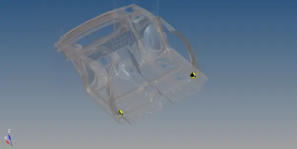
The above image show the accelerometers on the b pillar
- INTRUSIONS
Here, nodes are created at 2 nodes where the displacement of elements are noted down checked weather the crash occurred in the occupant area in minimal or maximum.
(create >intrusions>select the nodes >frame>select the local skew>ok)
(create>output block>entity>intusions>ok)
Model checker
Here , the model is checked for the errors using the model checker if the model checker is passed then stimulation should be started using the radios
Analysis
First check for the dry run if the errors found in the stimulation are 0
Go for the real time running of the model
(analysis >radioss>include connectors>-nt 4 >save as>project0000.rad >ok)
OUTPUT
Hyperview
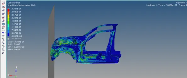
The above image shows the von mises stress
Energy Graphs
From the graphs it shows the kinetic energy goes on decreasing as the velocity decreases the KE also decreases and the internal energy goes on increases .internal energy is something which are the shocks are the jerks that absorbed by the occupant .
Total energy is the summation of the contact energy, hourglass energy , kinetic energy ,
Contact energy : it is the energy to avoid the penetration of the elements
Hourglass energy is the almost minimum due the selection of the Qeph
Cross sections
Bumper area cross section
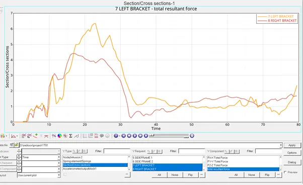
Fig of the bumper cross section area
In these condition we know the bumper is the first area where the whole component come in contact with the rigid body . from the bumper the forces are distributed to the component
From the above graph we can observe that the force observed by the LH- side is comparatively more than the RH side
This is due the cog as the cog point incline towards the left side of the vehicle the mass distribution is slightly more towards the left side which in results make the vehicle incline towards the left side of the vehicle
From the above fig we notice for the first 3 sec there would no change in the graph as there is no contact .when the velocity comes into the act major impact on the front bumper is seen around time (T=12-25)
Force absorbed on the left bumper side 6.3kN
Force absorbed on the RH bumper side 4.2 KN
SHORT GUN CROSS SECTION
Here , the short gun area is also known as fender . it is absorbs the maximum energy it is aligned next to the bumper component .from the bumper it absorbs around 20 % energy .
It directly protect the a pillar material by absorbing the maximum crash
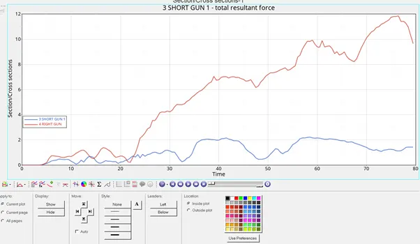
Short gun cross sectionarea
From the graph we can find the deformation on the fender is seen after 25 ms its because for the first 25 sec the rail component absorbed the energy after the component is deformed it allows load on the fender then fender which tends to deform after 25ms
Maximum deformation is seen in the left short gun =11.9KN
Where in the right short gun the maximum force is seen around = 2.1kn
Rail component
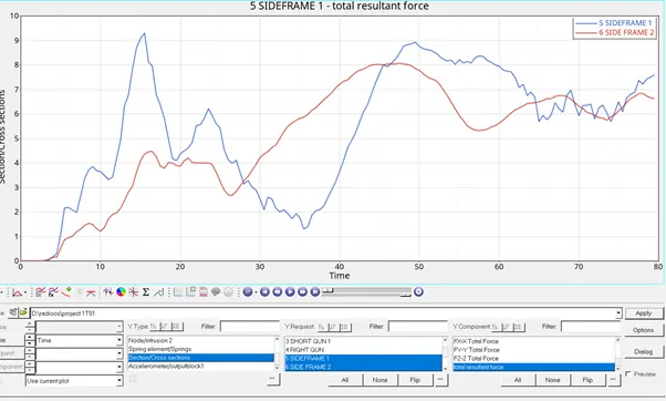
image shows the rail component stimaulation
The rail component is also present next after to the bumper whuch absorbs the maximum power from the bumper .which also protects the interior part of the component
These absorbs nearly 60% of the energy from the bumper
As it is present next to the bumper the deformation occurs immediately in the component at the T=15 we can see the deformation occurred rapidly and decreased after a time
Due to the contact with the other exterior component force is applied from the both the ends which tends to increase in the material deformation F=9.2KN at t=13
And in the right frame it is found that
Maximum deformation and load is applied on the left Rail component is 7.5KN at T=45
A PILLAR CROSSECTIONAL
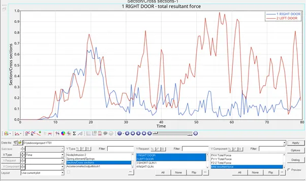
A pillar cross section for the both the ends
Here, it receives very less amount of the force compared to the other component
It is so because the material distribution is less compared to the other and it is designed in such away because it is the area where the occupant rest
For these the force is recived from the fender component .
Maximum force is found in the left rail which is 0.99KN at T=55ms
And for the right rail it is maximum force=0.63at T 25
The deformation in these component is found uneven because of the uneven distribution of the material and due to the element inclination the forces distributed unequally
B pillar cross section
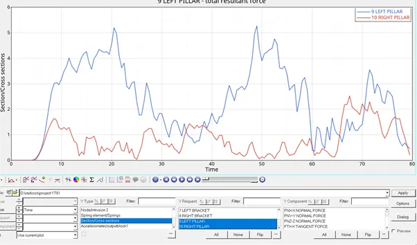
B pillar component cross section
As these component is connected next to the rail component it absorbs the maximum amount of force from the lower rail component which is connected directly to the body .
Maximum amount of energy is seen on the left B pillar =5KN at T=20 for the right it is seen as the F =2.4KN at T =65ms
ACCELEROMETERS
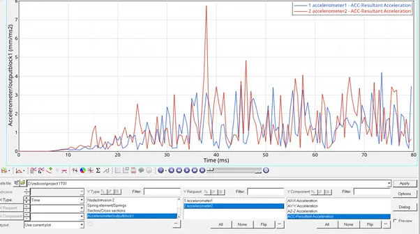
Accelerometers curves
Accelerometers are used to note the change in velocity occurred after vehicle is crashed and the points are selected on the B pillar area.
In a real time these are replaced by the sensor which calculates the jerks .from the graph at the peak point of the accelerometer is the point where the occupant is subjected for the maximum jerk
From the graph it is seen that maximum jerk is seen on the left side which is seen 7.5KN at T =36ms
INTRUSION
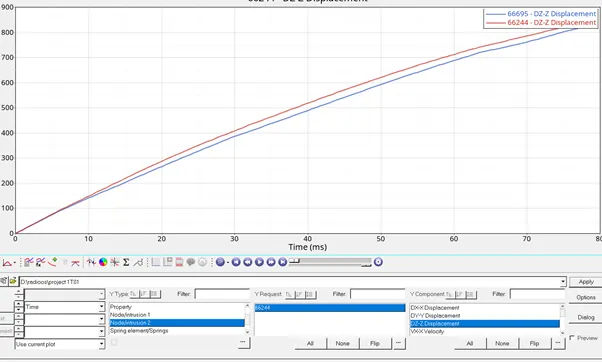
intrusion graphs
Intrusion point displays the displacement occurred in the components after crash
Intrusion points
In these analysis the intrsion points are considered at the brake and the food pedal areas
In these the maximum intrusion is occurred that is =890KN at t=80ms displacement occurred is maximum due to the absence of the engine component which in real time experience absorbs maximums the number of forces and allows to the point
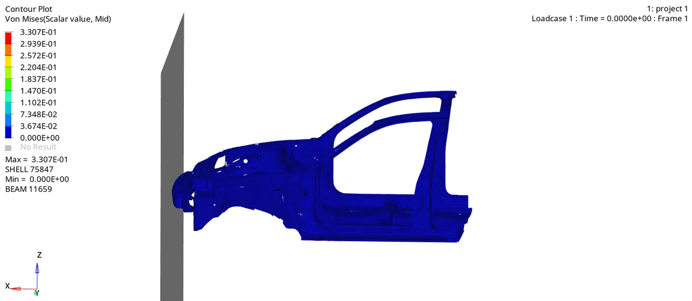
vonmises animation
Outcomes
- learnt how to create the rigid wall for the given type of the anlaysis .
- learnt how to change the COG of the material
- learnt how to create the sections for the at different areas and found the force absorbed in that sections
- learnt how to create the accelerometers and intrusion points
- learnt how to perform the penetration for the whole model
- learnt how to perform the model checks
links for the project model ishttps://drive.google.com/file/d/10oNf4dUDveBiy5ZXraT0e5_P_fRM1fZx/view?usp=sharing
https://drive.google.com/file/d/10oNf4dUDveBiy5ZXraT0e5_P_fRM1fZx/view?usp=sharing