Injection Molding and Injection Mold Nomenclature - Challenge 1
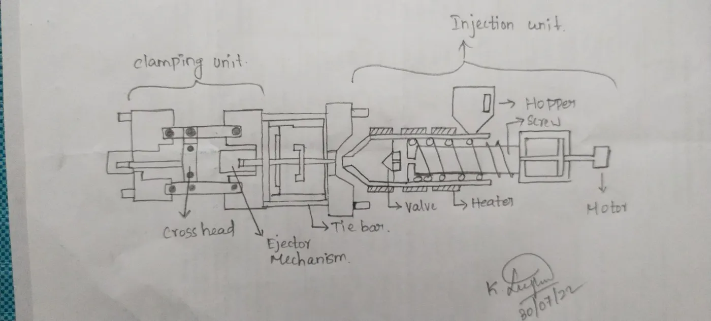
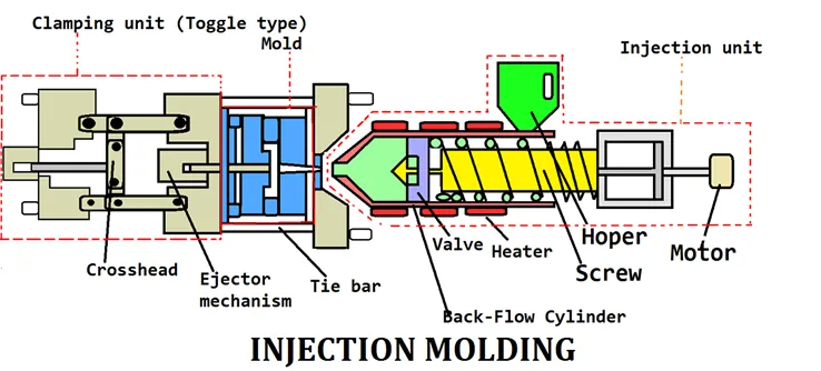
- Injection Moulding machine parts:
- Clamping Unit
- Crossheads
- Ejector Mechanism
- Nozzle
- Injection Unit
- Barrel
- Heater
- Backflow cylinder
Clamping Unit:
The moulding of the Injection machine has a clamping unit either the hydraulic type or the toggle type. It is available to hold the pressure developed and withstand the forces and stresses.
Crossheads:
The clamping mechanism for an injection moulding machine has got a toggle link, a crosshead linked to connected to the toggle link, and a driving device for moving the crosshead.
For driving the crosshead, the ball spline shaft is provided parallel to a ball screw. Also, a ball spline nut provided in the crosshead is attached with the ball spline shaft so that the crosshead may be controlled by the ball spline shaft.
Ejector Mechanism:
After the process is finished, the rod of the injection machine will push the ejector plate. The ejector plate will forward toward the right. Those moving the ejector, guide pin will constraint the motion.
Ejector pins clamped between two ejector plates so it will move forward and push the product out of the mould. The rod of the injection machine will move back after we get the product. Spring of return pin and mould closing will guide the ejector back to the position.
So, it will push the ejector plate to move back.
Nozzle:
A nozzle with the structure without stagnation is desirable. Using the needle shut off nozzle and torpedo nozzle due to resin stagnation control.
The best one is the open nozzle. Drooling, stringiness is easy, and it adjust independently the temperature at two separate places of the tip and the bottom.
Injection unit:
The improvement of poor appearance of the mouldings, the reduction of size unevenness between the moulding shots, and the measures against sink marks, warpage and flash can be achieved by controlling the injection rate, holding pressure, screw rotation speed and backpressure with multistep program control at the time of injection.
Barrel:
The barrel is made up of glass fibre reinforced grade and optical grade it is good to consider the barrel material. As it is good to use the bimetal to prevent the barrel abrasion for glass fibre reinforced.
Heater:
The material is moulded at high temperature, the heater with heat capacity can be heated to about 370℃ is used, and a band heater is usually used.
It is easy to cause the burn when continuing moulding without being aware of heater disconnection. Parts are disassembled to set the nozzle and cylinder head and when the heater is stuck with resin when the heater is disconnected.
Back flow Cylinder:
The screw head contains a backflow prevention cylinder in order to maintain the effects so that injection pressure by preventing a part of the measured. Resin maintains the ditch of the screw at the time of injection.
It is easy for resin with this valve structure to maintain the flow. So, the design of the flow path to provide the corner as much as possible is expected.
For high viscosity material, the fatigue failure occurs in the screw of the small aperture because torque is large when receiving the load by repeated rotation, the use of screws of a wide aperture is used.
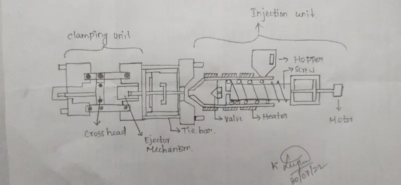
Free hand sketching of Injection Moulding machine:
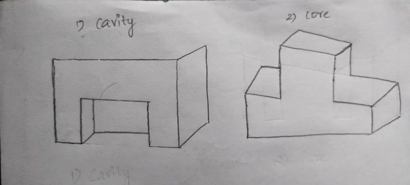
- Cavity:
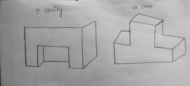
The machined shape within a mould which created the form of the plastic part. The plate used to fit the cavity insert, the cavity insert will have gap of the details to fill the plastic material and form plastic component Cavity plate usually of mild steel material cavity.
Core:
A protrusion or set of matching protrusions, which form the inner surface of a plastic part. They are often considered they “male” side of the part. The plate used to fit the core insert, the core insert will have projection and will create hallow portion in plastic component.
Free hand sketching of Core and Cavity:
- Ideal wall thickness of the injection moulded component:
|
MATERIAL |
UNIT (mm) |
|
ABS |
1.143 - 3.556 |
|
Acetal |
0.762 - 3.048 |
|
Acrylic |
0.635 - 3.81 |
|
Liquid Crystal Polymer |
0.762 - 3.048 |
|
Long-Fibber Reinforced Plastic |
1.905 - 25.4 |
|
Nylon |
0.762 - 2.921 |
|
Polycarbonate |
1.016 - 3.81 |
|
Polyester |
0.635 - 3.175 |
|
Polyethylene |
0.762 - 5.08 |
|
Polyphenylene Sulphide |
0.508 - 4.572 |
|
Polypropylene |
0.635 - 3.81 |
|
Polystyrene |
0.889 - 3.81 |
|
Polyurethane |
2.032 - 19.05 |
|
Rigid PVC |
2.286 - 6.35 |
|
Soft PVC |
0.635 - 3.81 |
- Minimum precision that can be expected of an injection moulded component:
The precision of the mould mainly depends on the high precision of the mould cavity size, accurate positioning of the cavity or whether the precision of the parting surface meets the requirements. The dimensional tolerances of the general precision injection moulds should be controlled below 1/3 of the dimensional tolerance of the products.
- Stages of Injection Moulding:
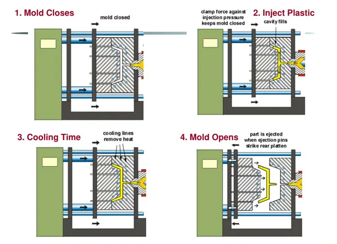
- Mould Closes (Clamping):
- Before injecting the mould substance, the proper closure of the two clamping units is essential to hydraulically empower the dual halves of the mould, followed by subsequent up force pressure.
- Further to this, the moulder must ensure the proper closure of the clamps to prevent the material from spreading or injecting externally.
- Large machines have longer clamped duration as compared to smaller ones.
ii. Injection:
- In this, the hopper drops plastic pellets into the mould machine, allowing these pellets to move towards the injection unit.
- Further, the heat wrapping the injection unit at a pressure of 35-140 MPa forces the pellets to melt.
- Next, the time of injection stands completed when 95-99% of the mould is filled.
iii. Cooling:
- Cooling refers to the lowering of the temperature of the plastic within the mould machine.
- This plastic keeps solidifying with time and takes up the desired mould shape.
- The thickness of the inner walls and the thermodynamic properties of plastic determine the duration of cooling.
- Finally, only after the elapse of the cooling period should a moulder open the mould.
iv. Mould Opens (Ejection):
- This refers to the final stage in the injection moulding process.
- The mould designer needs to apply extra force while opening the solidified mould.
- Consequently, the moulding machine forms a complete ready-to-use mould while further allowing the moulder to reiterate similar steps for designing similar moulds.
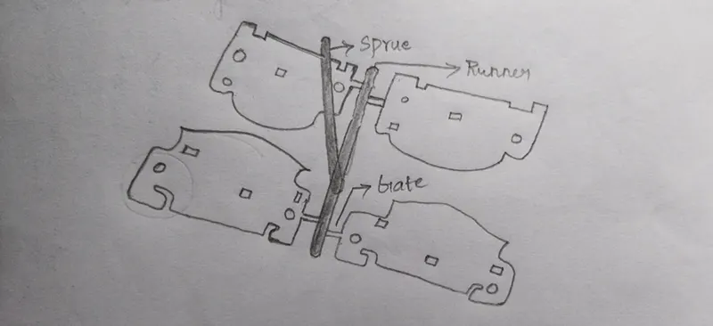
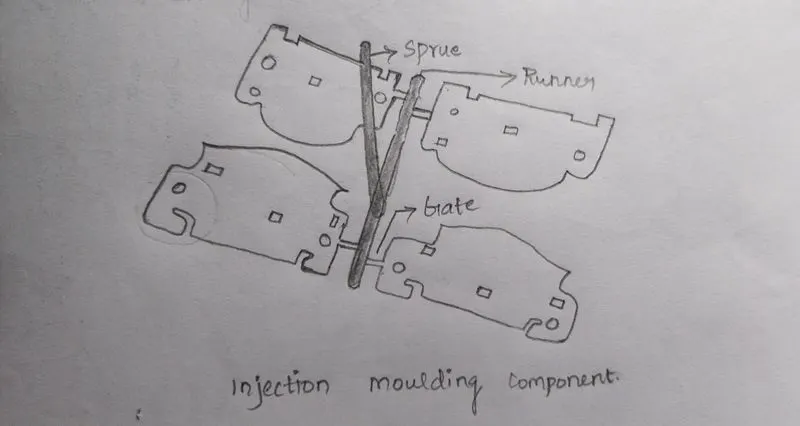
- Detail of Injection moulded component along with Sprues, runners and gates:
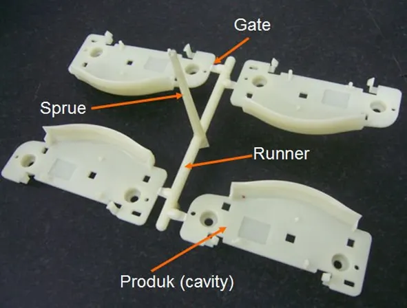
Sprues,runners and gates fulfil the function of conveying the plastics melt from the nozzle of the injection unit to the individual cavities.
- Sprues:
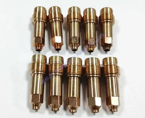
In fact, it is the point of contact between the mould and the manufacturing machine. Sprue is the passage through which the liquid substance (for example, polystyrene or polyvinyl chloride) will move into the die, where that substance cools down and solidifies to create components.
The sprue retains a concave spherical seat, and it is crucial that the sprue seat and nozzle tip retain the same radius. If the sprue seat and nozzle tip have different radii, the material tends to leak, making the parts inconsistent. The molten plastic flows through the sprue, and it reaches the runner system. But there are some exceptions. For example, in huge parts, the sprue can function as both gates and runners. It is called direct sprue gating.
The single-cavity moulds retain direct sprue gating when the sprue is linked directly to the moulded component. Primarily, the cooling period of the sprue specifies the creation of a single-cavity mould.
2. Runner:
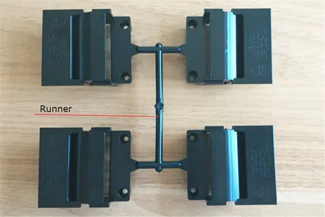
Runners for multicavity moulds are particularly important. A runner must be designed well so that each part is filled at the same time during a single shot in a family mould.
By adjusting gate locations and/or runner section lengths and diameters, you can achieve balanced flow to each cavity while reducing over-packing and flash in the cavities that fill first.
In addition to providing balanced flow between each cavity, moulds producing multiples of the same part should also ensure an equal distance between the injection machine nozzle and gate on each cavity.
The spoked runner is normally a choice. However, a spoked runner may not be very efficient as the number of cavities increases due to cavity spacing, or as the size of cavities increases.
When possible, it is preferable to arrange cavities in rows rather than circles. Runners are typically divided into rows consisting of main feed channels, and sub feed channels at the ends of the flowing path.
Generally, the diameter of the runner increases as the increase in number of cavities on that runner segment, since the flow path to each cavity must be of equal length and make the same number.
If the mould feed rate is constant, flow-front velocity between each cavity will remain constant. If the press cannot maintain an adequate flow-front velocity, the number of cavities that can simultaneously be moulded may be limited.
An artificially balanced runner can produce an evenly filled runner, thereby reducing the volume of the runner. These runners may have segments of varying diameter that are adjusted to compensate for the length differences of the runners’ segments.
A ladder runner, one of the most commonly used artificially balanced runner designs, contains two rows of cavities in a primary runner that is fed by equal-length secondary runners. Typically, the sub runners of these cavities are made progressively smaller for the flows which have the shortest distance between the sub runners. These designs require sufficient sub runners to balance the flow using reasonable sub runner diameters.
A runner for three-plate moulds burrows through the middle plate perpendicularly to the cavity parting line after conveying material along the runner-split parting line.
Projecting from a main runner, tapered drops are usually set on the part surface via pinpoint gates.
The drops in the mould reduce in size as they go toward the gate at a rate of approximately 0.5 inches per foot. Avoid the use of long drops, since the taper can cause excessive thickness at the runner junction.
3. Gate:
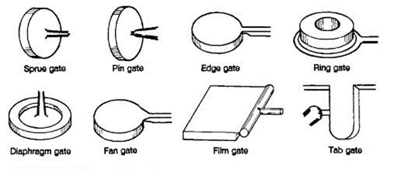
The gate is a narrow intersection between the main runner and the mould cavity, and the intersection is also the shortest part on the whole mould.
Its function is to make the molten plastic enter into the mould cavity quickly, which is beneficial to the rapid filling of the cavity.
After filling, the gate is condensed first to block the cavity, prevent the melted plastic from falling and avoid the pressure drop of the cavity too fast
Free hand sketching of Injection moulding component: