Fender Design
FENDER DESIGN
AIM:
To design a front fender of a car by following the given master section as per the design considerations of OEM.
OBJECTIVE:
The main objective of this project is to design the BIW (Body in white) of front fender using the fender skin data and master section as the given data by using SIEMENS NX Software.
FENDER-INTRODUCTION:
Fender is the American English term for the part of an automobile, motorcycle or other vehicle body that frames a wheel well. Its primary purpose is to prevent sand, rocks, mud, liquids, and other road spray from being thrown into the air by the rotating tire. Fender are typically rigid and can be damaged by contact with the road surface
Sticky materials, such as mud, may adhere to the smooth outer tire surface, while smooth loose objects, such as stones, can be become temporarily embedded in the tread grooves as the tire rolls over the ground. These materials can be ejected from the surface of the tire at high velocity as the tire imparts kinetic energy to the attached objects. For a vehicle moving forward, the top of the trie is rotating upward and forward, and can throw objects into the air at other vehicle or pedestrians in front of the vehicle. Fender is a front outer side member of a car, which covers the wheel side. It has so many small features with ups and downs.
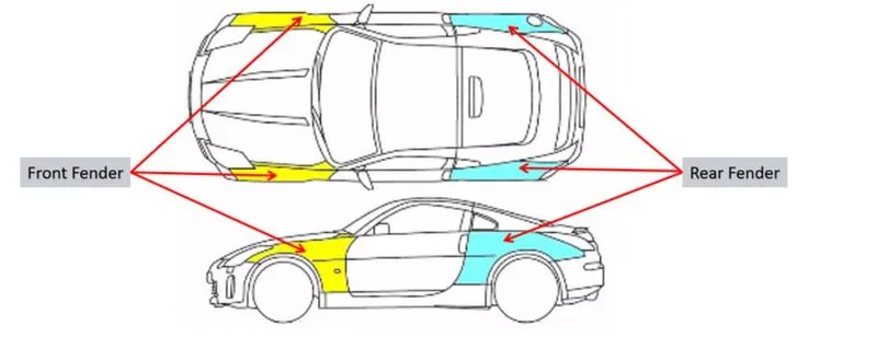
THE IMPORTANCE OF FENDERS :
- The fenders are an intricate sheet of metal covering the wheel well of your car.
- Fenders are designed in a manner to provide resistance against wind and other roadside debris.
- When you travel on rough terrains tour vehicle might get minor scratches and dents which look not better. Frequent road bumps can cause your cars paint to chip off which needs a paint job done.
- The car fender are located on either side of the front and rear wheels. The front car fenders begin where the front door hinges run and end just before the bumper. The rear car fenders begin where the back doors close and terminate before the back bumpers.
TYPES OF FENDERS:
There are mainly two types of fenders:
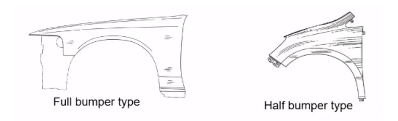
1. Full bumper type:
These types of fenders were used in earlier models of vehicles. They contribute to the major increment of the steel weight by just covering the front headlights with respect to the bumper region. The problem associated with this kind of fender is there is a lot of wastage in the blank and every inch of a material is a cost to the industry.
2. Half bumper type:
These fenders are mainly used for serving the purpose of cost-cutting and reducing enough proportions of the steel weight resulting in a reduction of the weight of the vehicle slightly. They can be economically manufactured, i.e by slightly increasing the blank size, we can produce two fenders at a time.
PURPOSE OF FENDER :
Cleanliness : Protect the car, occupants and passers by from items, water, mud, snow, ice, thrown off the tires as you drive.
Safety : Protects pedestrain from the wheel, e.g. its better to be it by a laterally moving fender than a rolling tire, keeps loose, streaming items from being wrapped up in a rolling wheel.
Aerodynamics : Smooths the car profile so you don't get a lot of drag off the uncovered wheels. Some fenders are enclosed on the side for this.
General Appearance : Looks better with fender, gives a finished look, looks more streamlined.
MANUFACTURING PROCESS OF FENDERS:
Mostly Fenders are manufactured by Metal-forming Process.
One of the most important things about metal is that it can undergo plastic deformation. That doesn't mean metal is made out of plastic, but it can do one of the things that plastics can: It literally can take on almost any shape that we can imagine.
The process of deformation begins with a Blank, a quantity of metal in some basic form that will undergo the change in shape. The blank becomes the workpiece - the piece of metal to be reshaped - in the metal forming process. For automotive metal forming, the blank is often made of sheet metal, which can be stamped, cut or bent into a shape needed for an automobile's body. Alternatively, it can be a solid block of metal in a cubical or lens-like shape. Here are some ways that a metal workpiece can be deformed during the automotive manufacturing process:
Rolling: Rolling in metalworking is a metal forming process that helps to reduce the thickness of metal and make the thickness uniform. The metal stock is passed through one or more pairs rolls to reduce the material. Rolling is classified according to the temperature of the metal rolled, it is a hot rolling if the temperature of the metal is above its recrystallization temperature. which it is known as cold rolling if the temperature of the metal is below the recrystallization temperature.
Bending: In bending, force is applied to a sheet metal workpiece to produce a curvature of the surface. Bending is generally used to produce simple curved surfaces rather than complex ones. A mechanically operated press drives a punch against sheet metal, forcing it into a simple die with enough pressure to produce a permanent change in the metal's shape. The amount of pressure is important. If not enough pressure is applied, the metal can simply spring back into its original shape. If too much is applied, it can break.
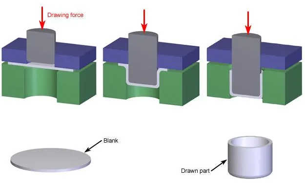
Drawing: In drawing, the sheet metal is forced against a die that has been cut into the three-dimensional, often curved shape that the sheet metal is to take on. In effect, the die is used as a mold for the metal. This technique can produce relatively complex shapes. Once again, pressure is applied to the workpiece using a hydraulically or mechanically operated punch. There are a number of dangers involved, not so much to people (since the process is largely mechanized) but to the metal itself. It can crack from too much pressure or wrinkle from its interaction with the die. Lubricant can be used to make the metal slide more smoothly against the die, avoiding the possibility of wrinkling. Alternatively, the wrinkled edges can be trimmed from the metal in a separate operation. This method is commonly used to make auto body parts and fuel tanks.
Stamping: In stamping, a device called a stamping press is used with a series of dies to cut and form metal into various shapes. This is commonly used to make auto parts such as hubcaps and fenders.
Forging: The forging process uses a hammer or press that is essentially a mechanized version of the hammers used by ancient blacksmiths. The metal is hammered against a surface that serves as an anvil. It can be hammered repeatedly so as to form complex shapes. This can be used as an alternative to the drawing process.
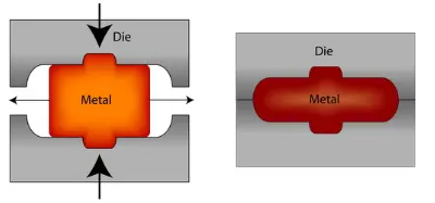
The above processes are generally used with cold metal. Hot metal can also be used, sometimes at high enough temperatures that the molten metal can be poured into a die. This requires very expensive dies that can withstand the heat and must be done quickly, to minimize the exposure of the die to the molten metal.
ASSEMBLY :
There are two types of assembly. They are,
- Bottom-up assembly
- Top-down assembly
Bottom -up assembly: The bottom-up assembly is the most preferred approach for creating assembly models . In this type of assembly the components are created in part design work bench ( As nx cad part) file. Parts are conceived in assembly design workbench using product structure tools . After inserting each component,constraints are applied to position them properly in the 3d space with respect to the other components. This assembly is preferred for large assemblies, especially those having intricate individual components .
Top -down assembly : In the top assembly design approach, components are created inside the assembly design workbench . There fore , there is no need to create separate part files of the components. This design approach is completely different from the bottom-up design approach. Here you have to create the product file first and then one by one create all the components. Note that even then the parts are created the product file , they are saved and opened individually one by one when they are needed . Here the construction and the assembly takes place simultaneously .
MOUNTING REGIONS ON FENDER :
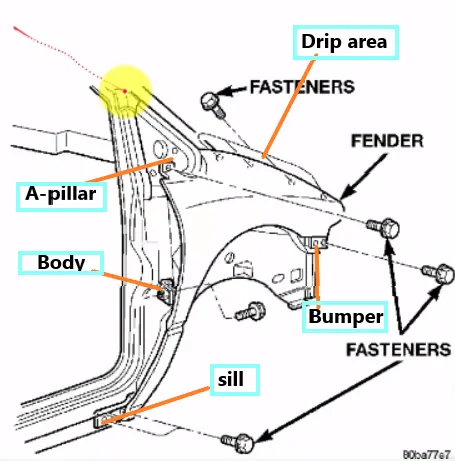
There are 5 mounting regions on the fender. They are,
- A- pillar mounting
- Body mounting
- Sill mounting
- Bumper mounting
- Drip mounting
DESIGN CONSIDERATION:
GIVEN DATA: (MASTER SECTION)
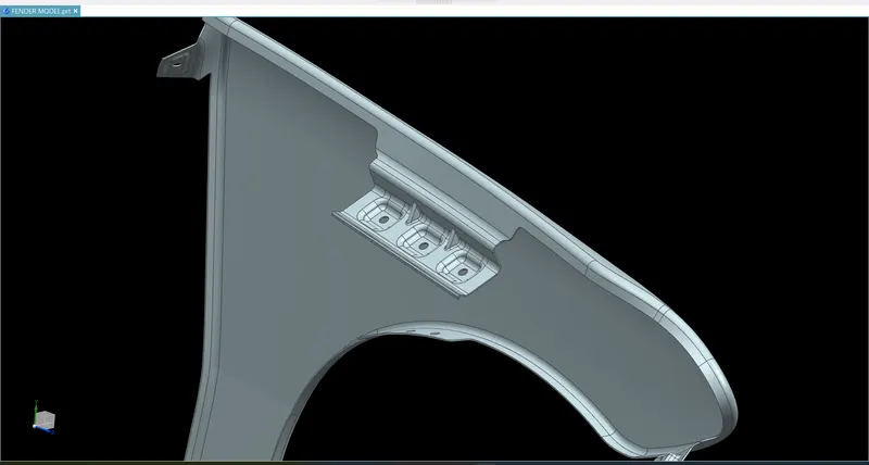
DESIGN 0F DRIP AREA MOUNTING :
- It is the important mounting unit of the fender. It is connected with the engine compartment, therefore the lot of design constraints are to be followed while designing the fender.
- While designing the drip area we have to initially leave 200-300 mm for cowl top.
- For placing the headlamp we have to leave at least 150 mm at the front while designing the fender.
- Cowl top part consists wiper motor and its instruments.
- Two darts are added on the longer side of the drip area in order to provide the stiffness and adds strength to the part . This helps the fender to not to vibrate and impact the forces outside of the fender during motion of the vehicle.
- Embossing are provided on the mounting to strengthen them during fastening
DESIGN OF SILL MOUNTING AREA :
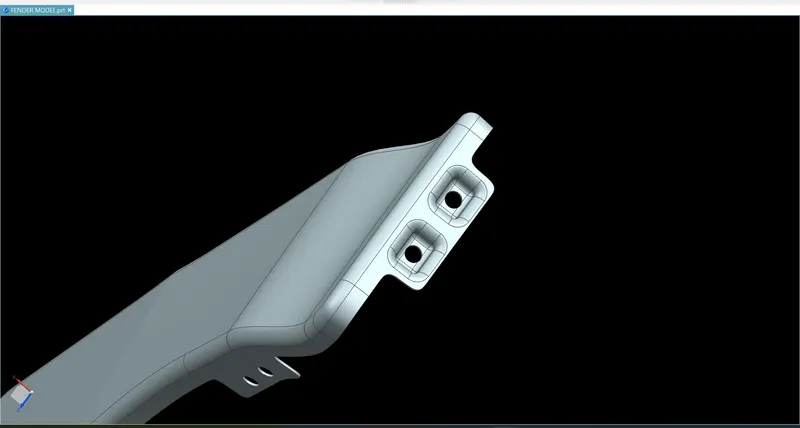
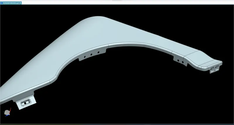
Sill is the panel directly below the bottom of the door supporting the floor and may be used to combine the floor and the body. The bottom end of the fender is mounted on the sill body for reinforcement of the fender panel , thus the sill mounting position is designed with holes and emboss. M5 fasteners are used to fix the fenders on the sill body.
DESIGN OF BUMPER MOUNTING AREA :
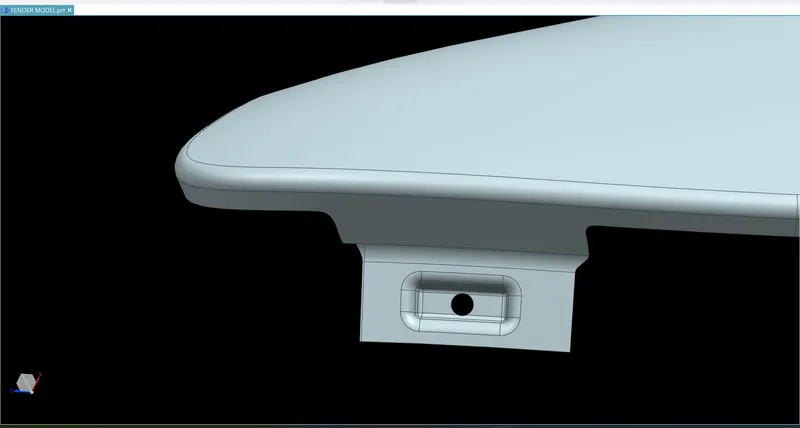
Bumper mounting area is used to fix the plastic bumper to the fender with the help of the fasteners.
DESIGN OF A-PILLAR MOUNTING AREA :
The A -pillar is the structural pillar that combines the body to the roof. This make the sides of the windshield rest. Front fenders are fastened to the A -pillar to form a robust structure.
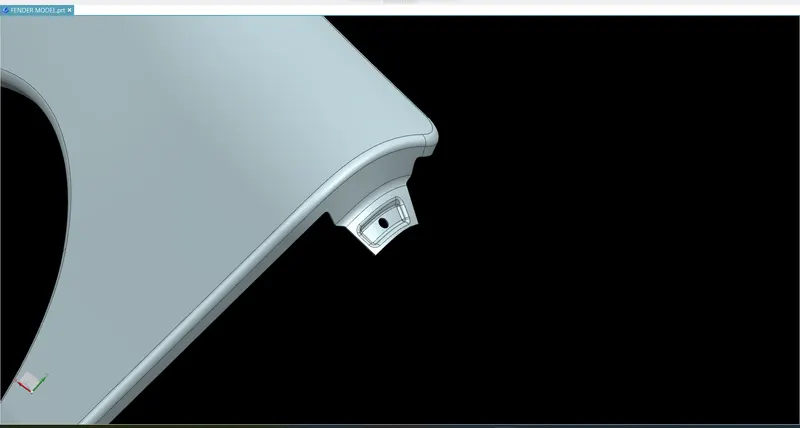
DESIGN OF BAFFLE MOUNTING AREA :
Baffle mounting or mudguard are clip fit type of mounting on the inner side of the fender arch over the Tyre. It protects the car engine compartment and pedestrians from causing injuries from chip out debris on the road when the car is in motion. They are mounted on the fender using a special type of locking clips which are made up of plastics.
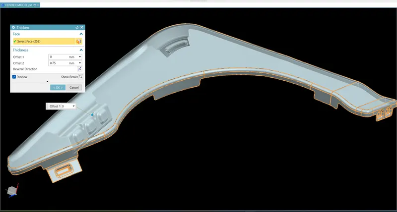
APPLYING OF THICKNESS TO THE SURFACE:
The thickness of 0.75 mm inward on the final sewed surface of the fender to the sheet metal parameters.
FENDER WITH DIFFERENT VIEWS:
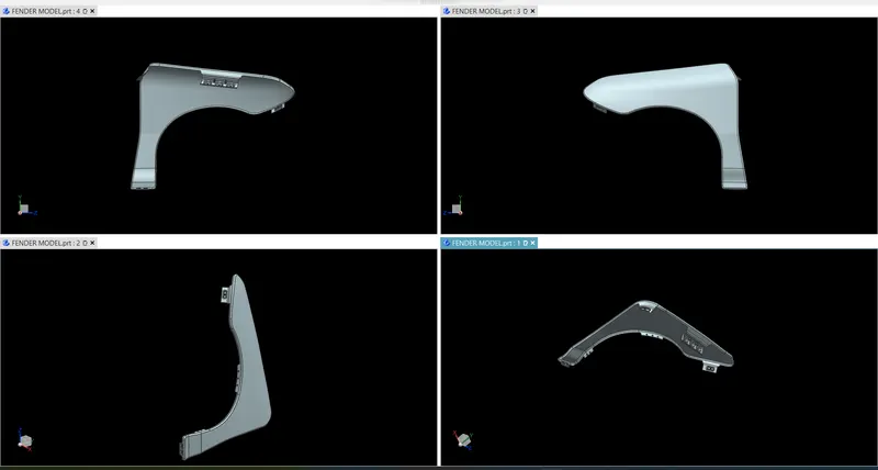
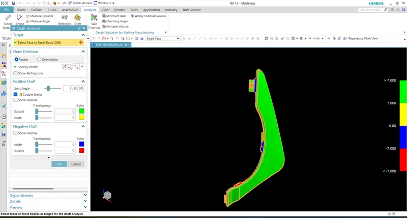
DRAFT ANALYSIS ON FENDER:
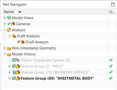
MODEL TREE:
CONCLUSION :
Finally design of fender is done with the help of NX-CAD software by following the master section.