Hood design-Week 2
DESIGNING OF HOOD ASSEMBLY USING NX-CAD (By : Pramod Mamillapalli)
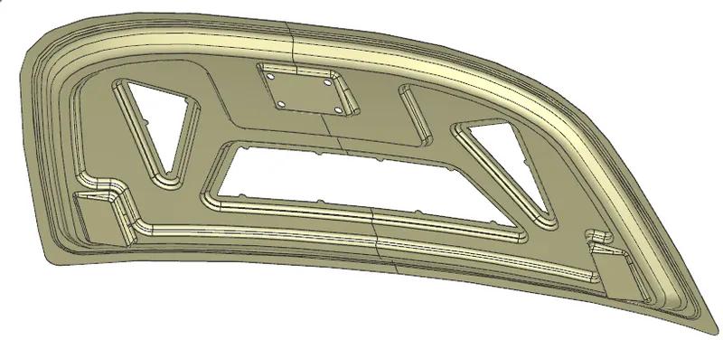
Here in this project we are going to design a Hood assembly for a car using the tool Nx Cad as shown down.
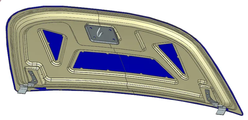
Introduction:
A hood is a front panel which helps to cover the engine compartment and also helps to enhance the looks of a car, it also provide safety for the pedestrians from the front impact goes on with the help of wrap around distance and also protect the engine.
pedestrain safety cosideration:
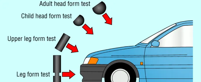
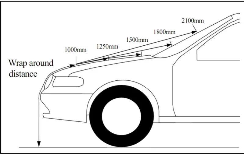
We cannot design the hood assembly in a single shot, for the designing of hood assembly we have to divide it into so many different parts and steps. They are as follows:
1. HOOD OUTER PANEL
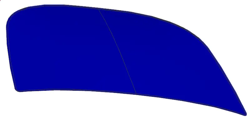
2. HOOD INNER PANEL
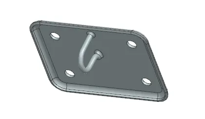
3. STRIKER
4. HINGE ASSEMBLY

Design Procedure - 1:
As per hood parts that we discused in the above discription we have to design the hood outer panel first. But for now outer panel is it self provided to us by the skill lync for the ease of designing and for better dimensioning. we just open that part file with the help of WCS coordinates.
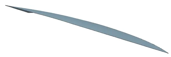
But only outer panel is provided without hemming so we have to do the hemming as our own after designing the inner panel with the help of master section as shown.
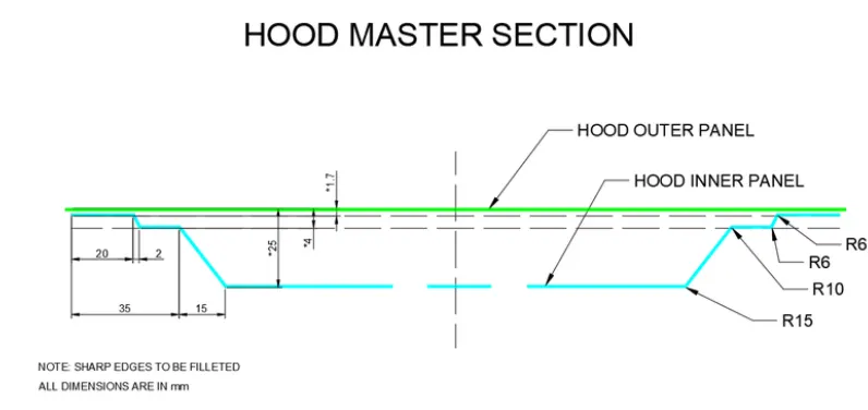
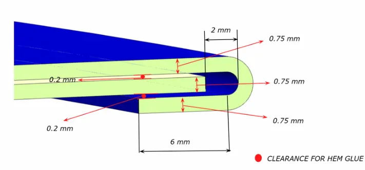
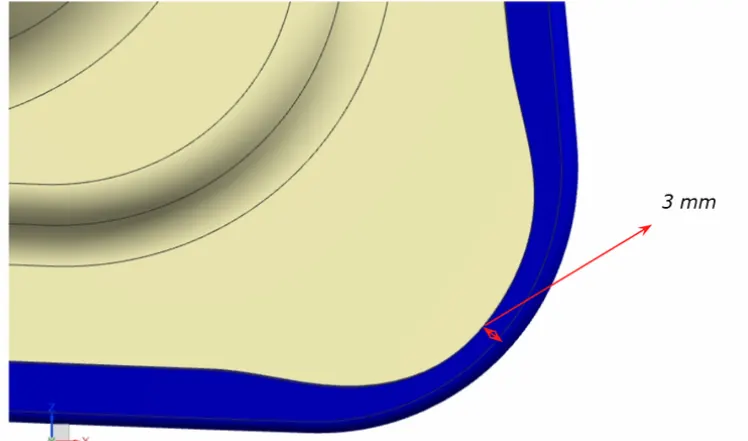
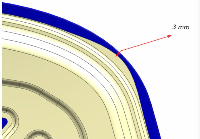
The above images indicates the hemminh clearance and front and rear hem relief.
so for now first we do the hemming process using the outer panel as reference with help of the master sections shown above.
Firstly we have to trim the sheet in to half for ease of designing and comfort. Then ny using the bridge curve tool in nx we have to draw a curved edge on the bonet corner for smooth hemming on the corner.
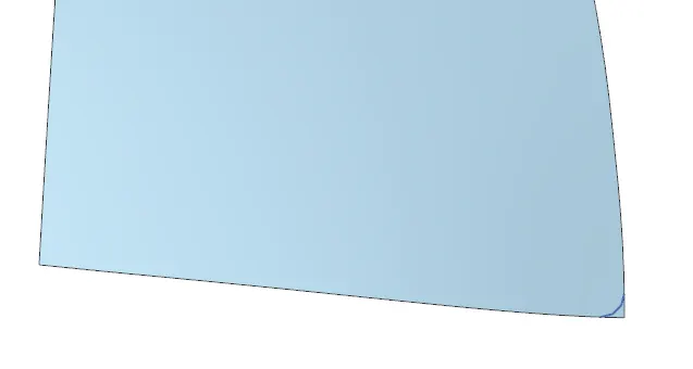
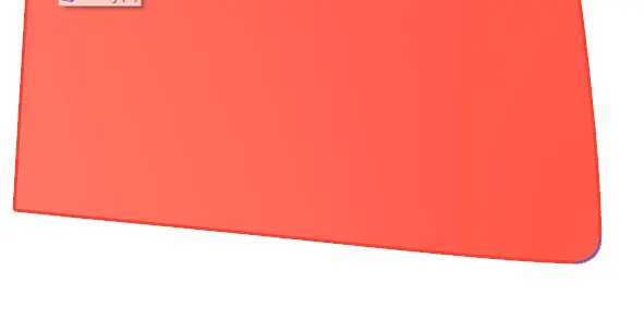
now trim that sharp corner which gives you soft edge as shown.
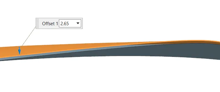
by using the offset surface option we do the offset of 2.65mm below the outer panel as described , after thickening it we will get 2mm of clearance in between both the inner and outer panels for application of hemming glue for good rigidity.
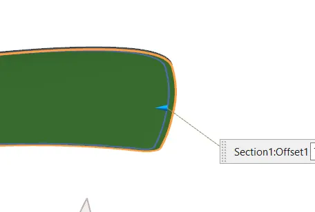
now we have to offset the outer lines to inside of 7mm as shown in figure for get the trim for heming downward portion in offset surface.
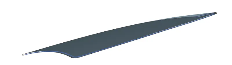
now we get the hem in lower portion of the outer panel now we need to create the cureve on edge by making a offset in the lower edge at 0.1mm and then we need to exted it upwards with law extension option.
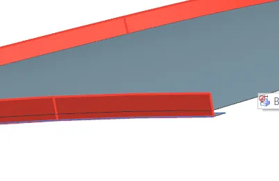
next to this we have an option called face blend there we have to use three face blend for getting a smooth ans curvy connection between two surfaces as shown. here we take upper panel as face one lower panel as face 2 and then extended part as middle face.
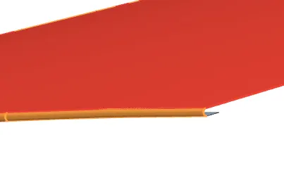
after doing this our hem is competed but in the process of rolling the hem it is not able to roll the sharp corners so for that we have to give a relief of 3mm as shown in the master sections above. For this we have to draw a curve in the surface there we get help with a tool called curve on surface. then after this we need to trim the extra material from the surface.
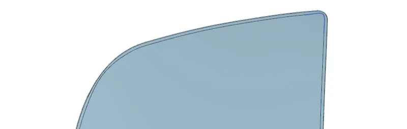
so our hemming is done now we have to mirror the hood to other side which gives you the full panel at one by mirroring these features at once. then we have to thicken it thickness of 0.75mm as required.
for chaging the appearances press ctrl+j and then we can change the colors. so for now we completed the outer panel with hemming process and hem reliefs.
Design Procedure - 2:
Now select the datum coordinates for sketching the hood inner panel in WCS for ease of designing. Now after selecting the coordinates we have to extract the face from the given outer panel as shown, then trim the surface into half add it in a feature group and name it as parent group.
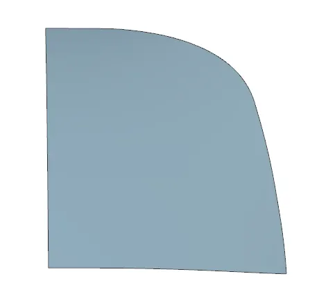
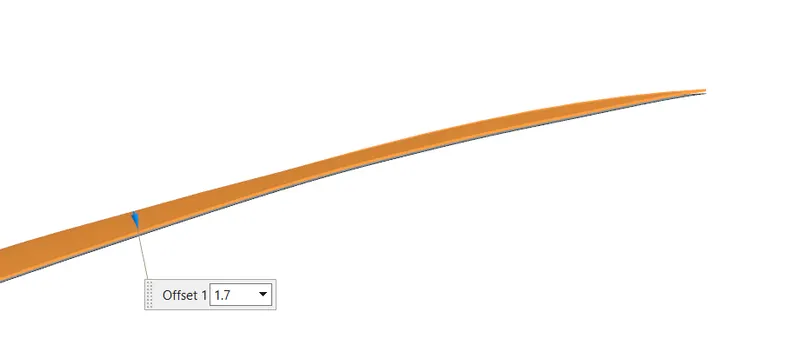
After that make an offset surface below the given panel with measurement of 1.7mm
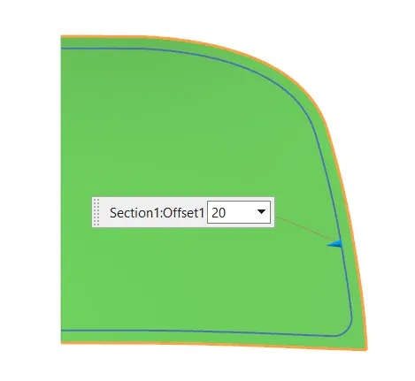
now we have to offset the edges by using theofset in face option at the distance of 20mm in side on offset surface.
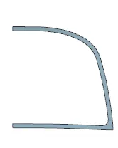
now trim the inner portion of the offset surface as shown in the figure and hide the extracted surface.
again offset the surface of about 4mm inside then offset the curves twice at distance of 22mm and 35 mm inside direction as shown and then trim the part to get this surface.
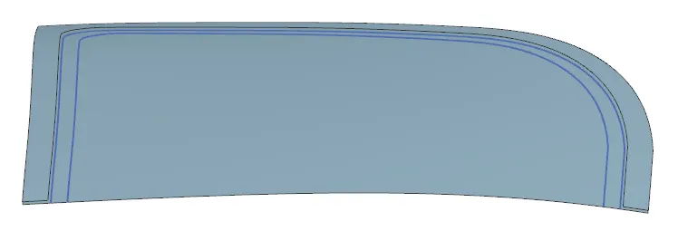
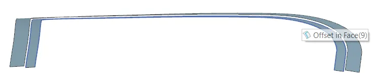
after these again offset the surface at 25mm downward and then offset the curve at distance of 50mm and then trim the sheet for this third layer as shown.
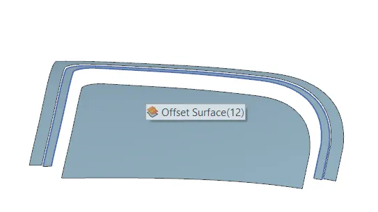
now we created the three layers of surfaces and then now we have to connect all the surfaces with the help of througn surface option and connect it as shown (while selecting the edges always select the tangent faces)
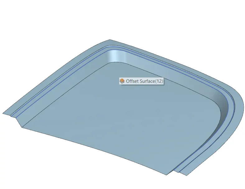
now by using the face blend option with the help of two face blend we have to create 6mm radius blend for smooth edge as shown in the design.
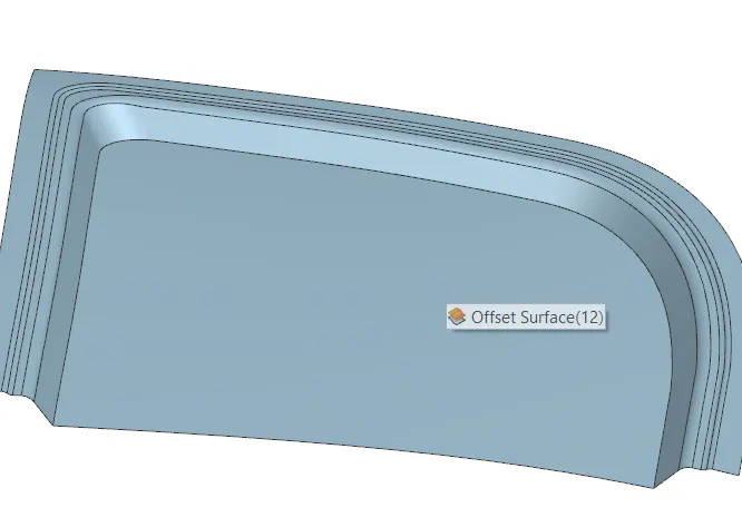
after completing the face blend there ia a tool called sew which helps to joint different surfaces in one, by using it we have to select all the three surfaces blends and curve sew together and make a single piece surface.
also make sure that lowe edge is also get blended otherwise use the edge blend option other than face blend for this at a radius 15mm.
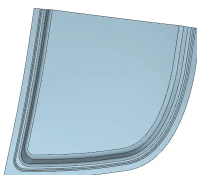
offset the last surface curve at distance od 20mm as shown
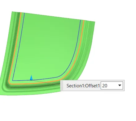
now sketch the inner panel crossection as the dersired shape of emboss on it example as shown
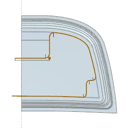
after this project the curve on the panel and emboss the sketch as shown i.e. opposite to the tooling directing, also give the edge blends radius of 5mm to the emboss.
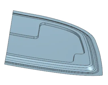
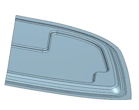
now again sketch on the plane for the internal embosses for the required saftey and crash distribution i.e. load on the hood with different crossections as shown. note that all the sketches has to be constrained properly. then do the projected curve on the surface for emboss at a distance of 8.5mm and then do the edges blended properly with the radius of 5mm. then our output as follows.
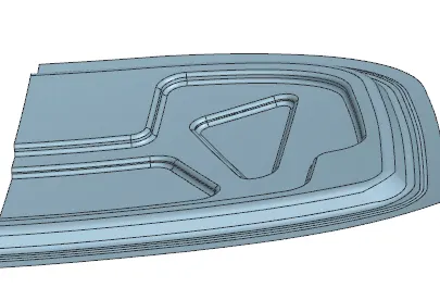
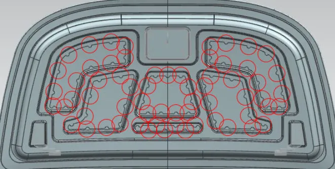
then do the sketck on coordinates with an offset of 10mm in the very much internal embosses with presence of mastic ponts with the clearance of 1.7mm which impacts 80mm dia for each mastic for reducing the noices and unsaftey. then project the curves on the surface then trim it.
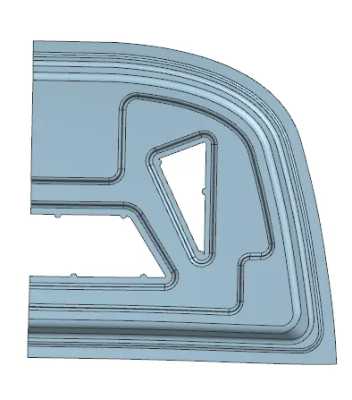
now create a sketch for the hinge reinforcements to get it fixed rigidly but here we need an extra plane for the plain face without any bends on it so we need to insert a new datum plane as far as possible to the surface sheet as shown after sketching then project the sketch towards the plane as it is reference as shown then we will get the perfect emboss.
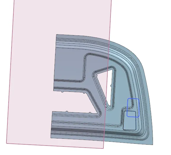
insert the edge blends with the radius of 3.75mm blend radius as shown in the design below.
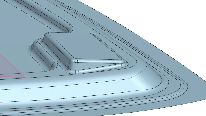
now extend the sheet on the mirroring side for a distance of 5mm to avoid the gaps between sheet after mirroring. it cannot be done in one time because some little extends will show some errors so when you get those errors leave it there and again start the extend freshly from the pending ones. and now trim the body normal to the plane to get the exact line of joint after mirroring.
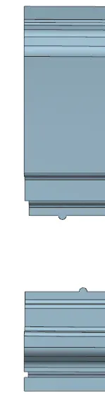
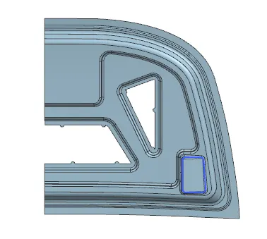
now mirror the surface with the help of center plane and then sew the part and check the errors if everything is ok combine the part to make an single sheet.
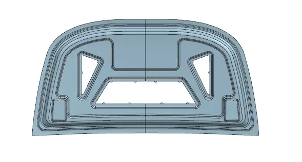
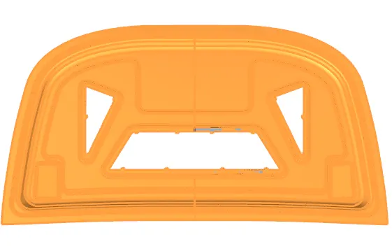
now go to the hinges and make it constrained and visible in the assembly with the help of assembly constrains. fix the inner panel and then apply the touch constrains between the bonet and the hinge as shown. then add a point in the axis of rotation of hinges and draw a line between two hinges. also constrain the hinge and hood parellel to the plane. after that add a datum plane between the two inges with the help of % arc length at 50% as shown.
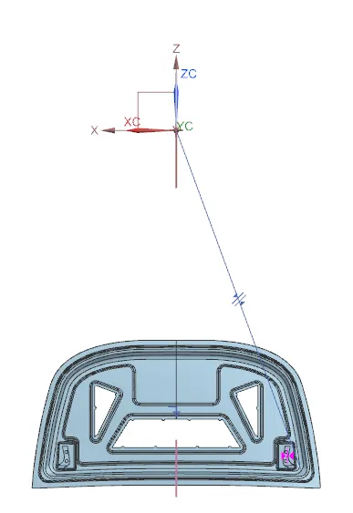
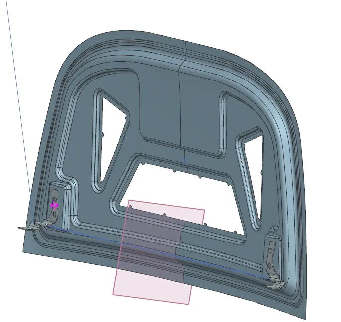
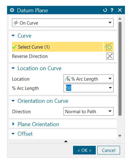
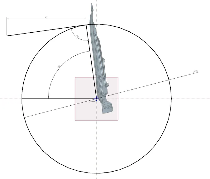
now sketch on the datum plane and draw a circle on the datum dia of 660mm and draw a horizontal line and a verticle line at an angle of 82 degrees and to that line draw a line at an angle of 90 degrees which is tangent to the circle which indicates the latch trajectory as shown. This trajectory plays a major role while designing the hood. it helps to close and open the hood properly by locking and unlocking it.
now take the striker and take a face with the help of linked face as shown with the help of sketch assign the latch and striker as shown to the drwan trajectory of hood. add a datum plane on the top of the stricker with % arc lenth at 50% help to assign at the trajectory.
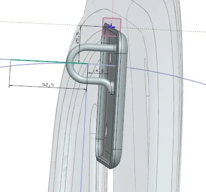
after extracting the linked face from the sriker do the law extension to that boundary at some distance covered to the inner panel as shown and sew them together with the inner panel.
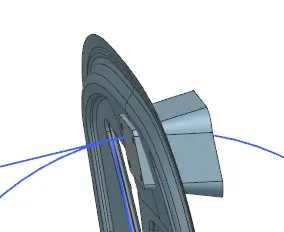
now trim and extend the unwanted material from the extension with trim and extend tool.
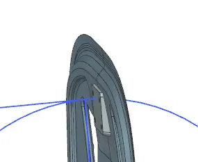
do the edge blends to the sriker mounts at the radius of 6mm.
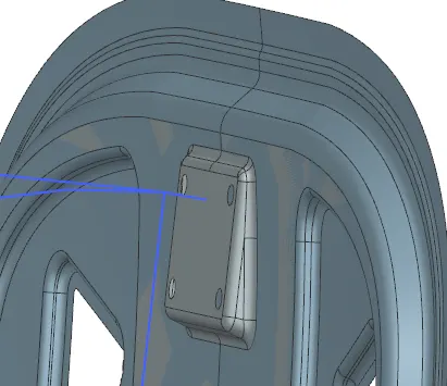
now same as the outer panel use bridge curve option to trim the sharp edges of inner panel as designed below then mirror the feature to the other side as well. after thar offset the over all boundary to 2mm distance inside the panel and trim it. this will get the clearance between hem.
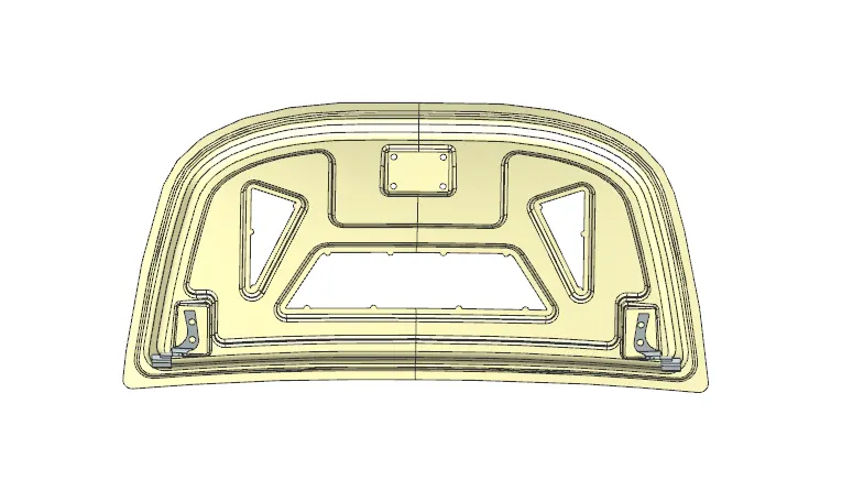
Now its a final step and we can conclude the inner panel by thickening it with thickness of 0.75mm and then chage the color and save it. finally adjust the striket mount distance to minimum as possible.
Design procedure - 3 & 4:
Here we also got the striker and hinzes by default from the master section it self.
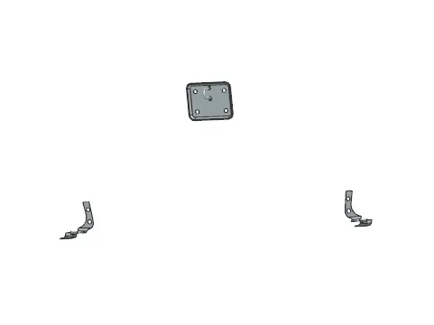
Final Hood Assembly :
Now unhide the whole components step by step and then contrain then with touch assembly constraind and striker with the trajectory referance sketches then we will get the whole assembly as shown below. After all go to clip sections and view the design into half to check the design is perfectly done or not.
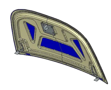
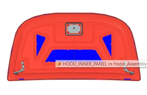
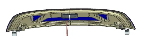
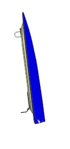
After this designing is done the part will be manufactures with the process called deep drawing process, which is used for sheet metals.
DEFINATIONS:
Deep Drawing process:
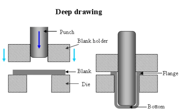
Deep drawing is a sheet metal forminfg process in which sheet metal black is radially drawn into a forming die with the help of mechanical punch. it is thus a shape transformation process with material retension. thye process is considered deep drawing when the depth of the drawn part exceeds its diameter. This process is shown in the below figure.
Hemming process:
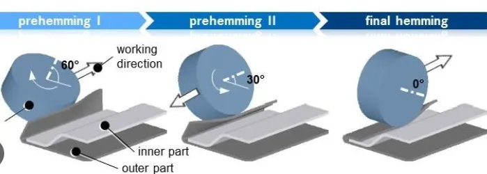
Hemming is a sheet metal forming process in which sheets are joined by bending it to 180°. Automotive body panels and automotive parts such as deck-lids, trunk-lids, doors, hoods and tailgates are formed by hemming process. In this process, usually a sheet is bent with the help of inner sheet in three different stages. This process is done with the help of rollers in different angles and processes as shown.
Mastic points:
Mastics are the glue stripes which helps to stick the two surfaces and will show impact around 80mm diameter of its surroundings. It also helps to improves the NVH (noise, vibrations, harshness)levels. It is explains briefly in the figure below.
Embossing:
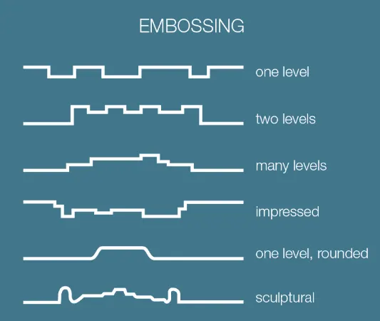
Embossing is a forming process in which a high pressure is applied to a workpiece to change its surface. Depending on the shape, a distinction is made between hollow embossing and solid embossing, sheet metal embossing. there are number of levels of embossing.
Concluison:
Hereby i conclude that by following the above procedure we desinged a Hood assembly with the help of different tools by using the simens nx cad software with different definations and theories help to design a hood and by satisfying all the pedestrian safety considerations as per the autonomous industrial norms. Here this project helps learn how to use different tools for the different procedures for playing with the different designs.