Fender Design
FRONT FENDER (by: pramod mamillapalli).
Fender:
Fender is the american term in an automobile body that frame the wheel well. Fender is a side body panel which helps to cover the internal parts and chasis of the car. Its primary purpose is to prevent sand, mud, rocks, liquids, and other road spray from being thrown into the air by the rotating tyre. Fenders are typically rigid and can be damaged by contact with the road surface. It also helps to pedestrians in accidental situations for not to hit towards the tyre and also protects by splashing of mud, sand, and other particles.
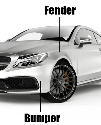
Generally car has four fenders they are front fenders on both the sides and then the rear fenders on both the sides. Which covers all the four tyres. Rear fenders also called as rear quarter panels of the car.
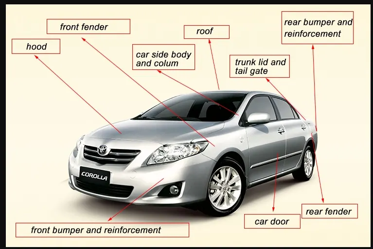
Partially front fenders are of two types. They are as follows.
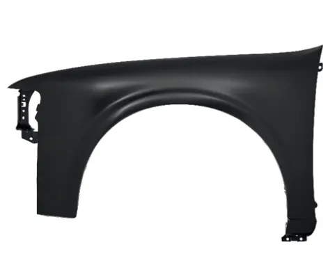
1. Full body type fender: These are the fenders which covers 80% of tyre as shown below but cost applies more.
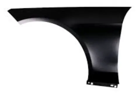
2. Half body type fender: These are the new type of fender which redused the material quantity and avoid wastage. It also increases the mileage and performance of a car.
Objective:
Here in this project we are going to design the fender and its mounts. There are five types of mountings are there which helps to snug fit the fender to the body of the car. They are as follows:
1. Drip area mount.
2. Sill mount.
3. A - pillar mount.

4. Splash mount.
5. Bumper mount.
Design Procedure and considerations:
As per the given skin data we need to design the all five mountings apart from the whole design. But in the given skin data the edge extension are more than required. If we de design as it is we will be getting some spring back effect.
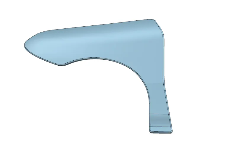
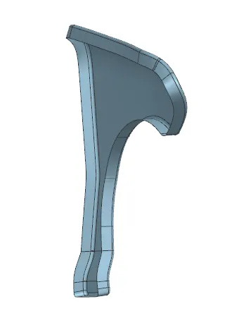
so now we have to offset the corner edge at a distance of 5mm inside with the help of offset curve in face option as shown.
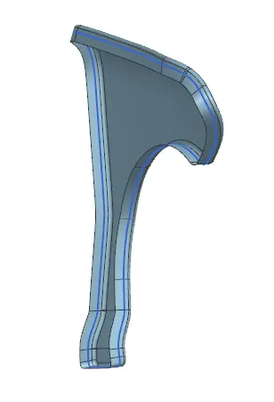
Now with the help of curve on sirface tool we select the single faces and create some splines with the tangent faces on either ends of the splines as shown in the below designs. For where we need to create mounts that should be kept asusual remaining will be trimmed.
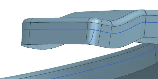
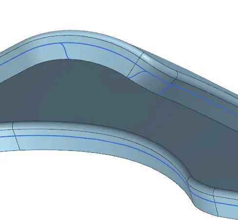
After creating splines with the help of curve on surface as shown above then we have to trim the extra unwanted sheet with the help of trim sheet option as shown.
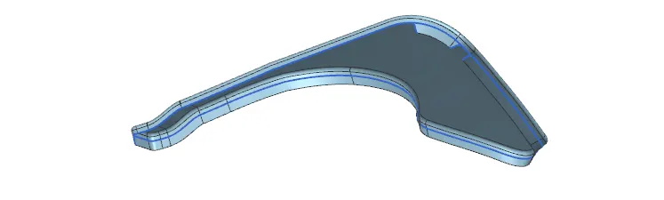
Then we have to extend the sheet at the a pillar point at a distance of 42mm with the draft angle of 90 degrees by seecting the desired planes for the required out put as shown.
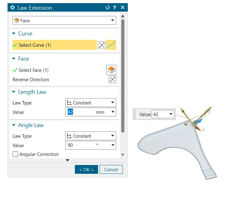
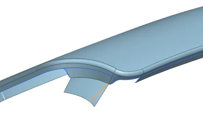
Now again we need to use curve on surface option for trimming of the extended sheet for removing the unwanted extra surface for reducing the waste and cost of production also these kind of designs helps in ease of production with less amount of extra chips and get precise out put.
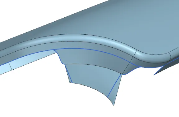
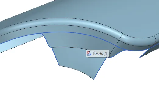
Now insert a datum plane at the distance of 150 mm from the A mount as shown. The other side will be automatically will be 200mm or above,
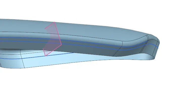
Now by using the intersection curve we have to draw a lines parellel to the two datum planes for the design of a drip area. And again insert another datum plane at an offset of 150 mm as shown.
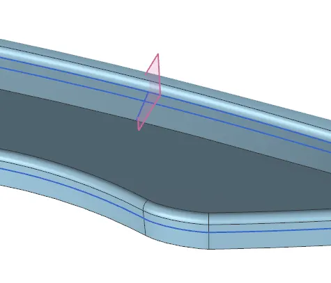
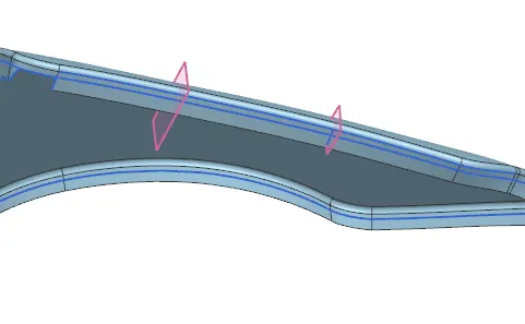
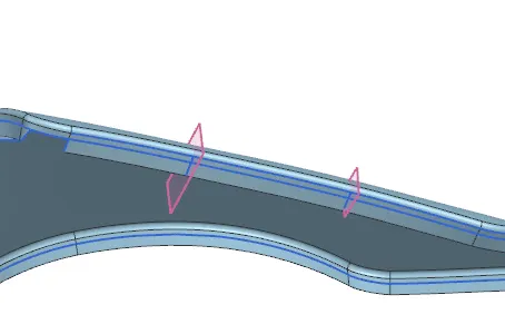
Now here we have to use the curve on surface option for trimming the drip area base for thr further design consideration as show for getting smooth edge with the help of spline. (We mostly use curve on surface otion for get the work ease and this tool is very friendly and powerful.)
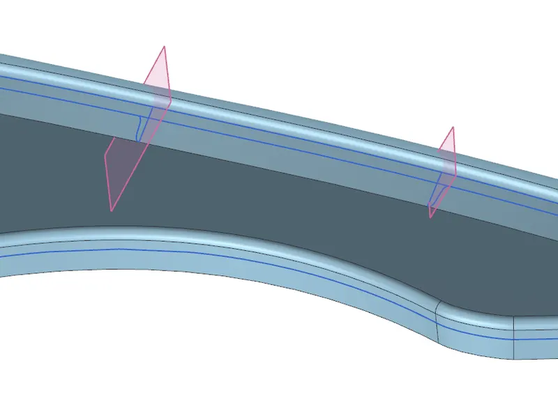
Now we just only trim the one side of the sheet which is needed for the design the drip area. Because we need to draw another curve on the other side which extend towards the bumper mount then we have to trim that as well.
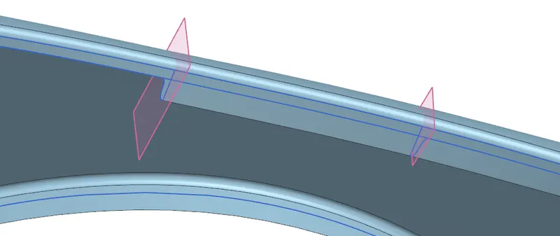
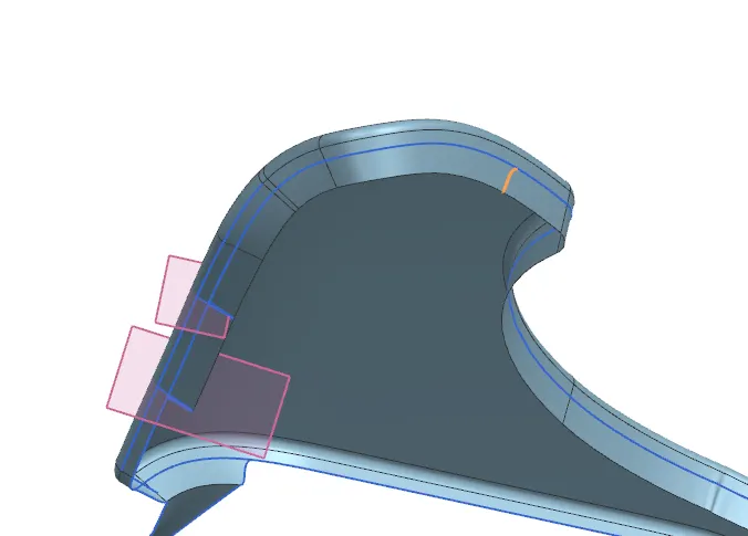
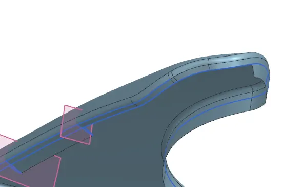
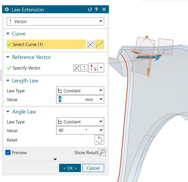
We use the law extension option for extending the first corner of drip area as shown in the given master section at the distance of 8mm at an angle of 40 degrees below as shown withe help of the desired contrains.
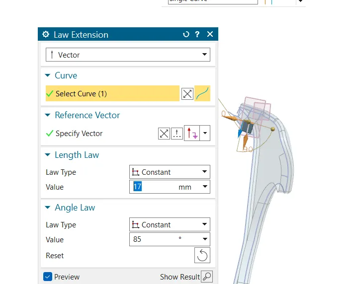
Then extend the other continuity as well at the distance of 17mm at an angle of 85degrees as shown for redusing the spring back effect. Again extend further at an angle of 0 degrees which is almost perpendicular to the previous one at the distance of 25mm where we design the drip area and darts for more rigidity.
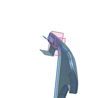
Now the tricky part comes for the further extension where we will get used the 2tanθ for getting the length of further extend. after calculating the length and angle of all the last three extends shown in the master section we will get the distance of 4.24 mm at angle of 45 degrees upwards as shown. Then we extend further at the distance of 1.5 mm at o degrees the the final extend will be 2mm at angle of 75 degrees which gets the design as shown.
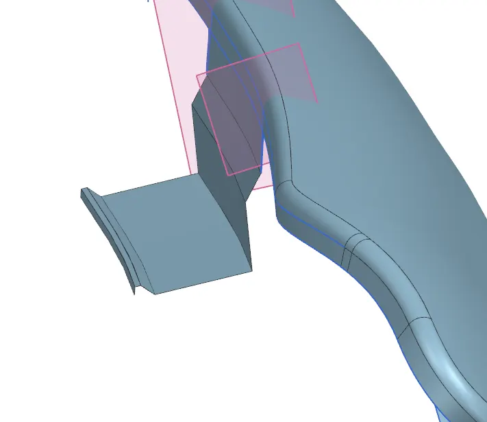
Now we use a new command called dart which helps to gib=ve more strength to the design at the measure of % arc length at two points at 50 % and 100% at an agle of 45 degrees and radius of 2 with depth of 3 mm by selecting the two faces which are perpendicular and cornered each other. Note: This command helps only at the sewed or single body surfaces.
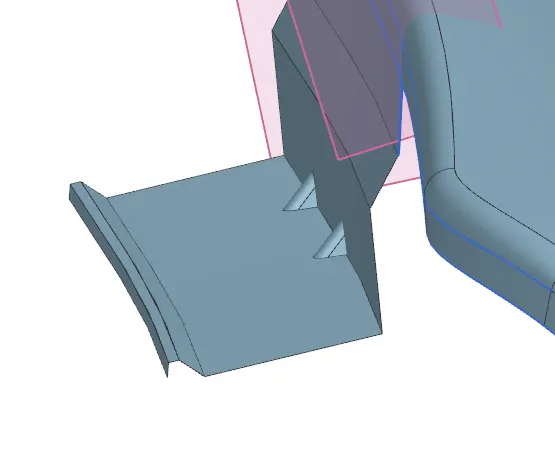
Also do some face or edge blends as possible at the edges for getting the smooth and plain surface which helps for ease of manufacturing with out any chipping.
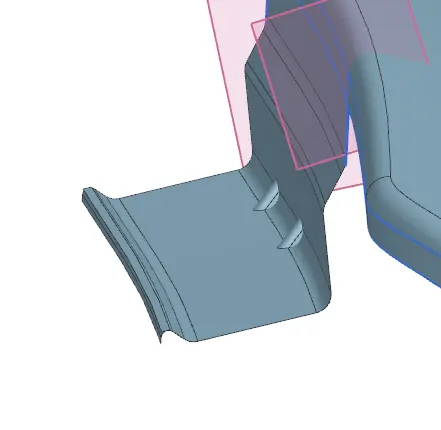
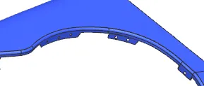
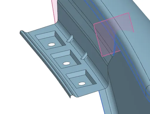
Now insert a datum plane at an offset distance of 100mm below the drip area by selecting the point surface option. Then draw the rectangles and circles of about 5mm radius for the hole to fit the fender to the body as shown and then project the sketch towards the drip surface then we have to do the emboss for the rectangles and the trim for the circle as shown below.
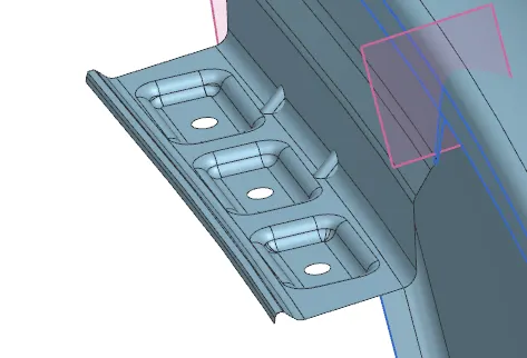
Then do the face and edge blends for smooth edges at the desires curvature as possible to your design considered.
Use the curve on surface option to trim the sheet for the splash mounts for the wheel arch and the sill by offsetting the curves as shown.
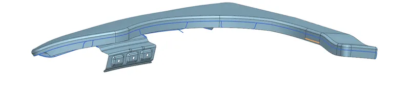
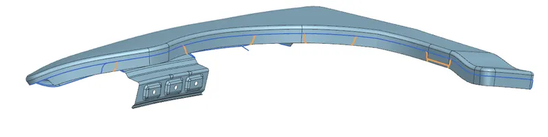
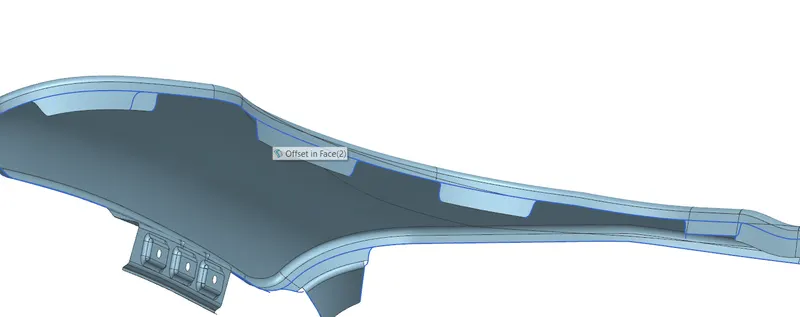
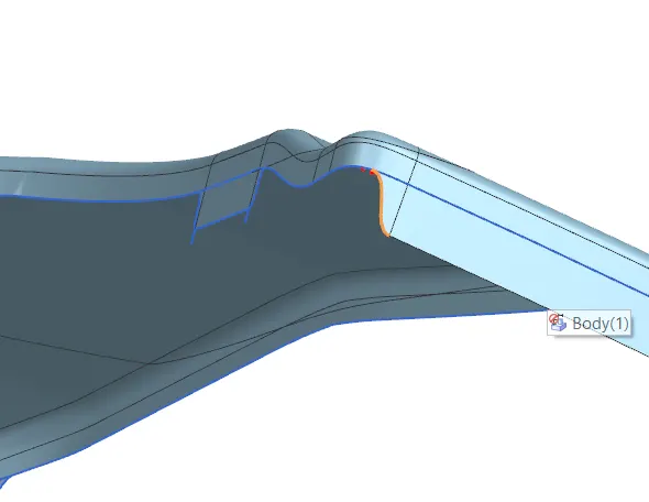
Now at the sill area same as drip extend the surface at 90 degrees and add a datum plane and draw a sketch with two possible mountings and do the emboss and blends as shown also make sure that the all edges must be smooth and curvy otherwise we can use the bridge curve uption for cut them off. You can also use curve on surface option as well
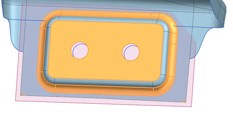
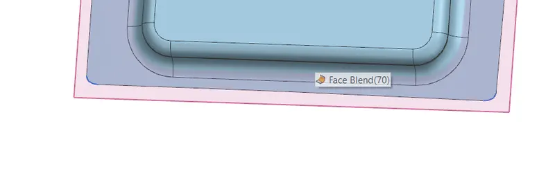
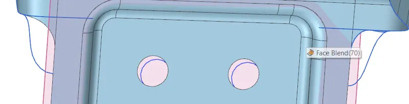
Now coming to the bumper support extend the edges and then apply dart on it then add a few blends to all darts for smooth and curvy edges and again repeats the datum plane do the sketch for emboss and the trims for the bumper support by projecting on it as shown, also add a few bends on it. Note that make sure that the emboss will be less as 20mm and sketch will be defined.
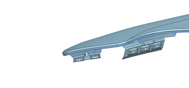
Then we will move to the splash mounts. Here we have to add three datum planes as usual done previously and the sketch on those planes for holes to fit the fender linings on it as shown, now trim them off as shown.
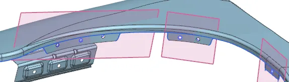
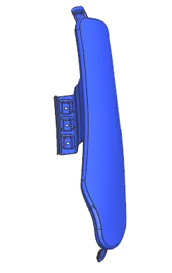
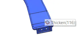
Upto here we have created the drip mount, sill area, splash mount, and bumper mount. Now the only pending one is the A pillar mount that we already extended. Now as we know the procedure we have to apply a datum plane and then we have to sketch on it then we have to project the sketch on the surface then we have to perform emboss and then we have to trim the holes we have drawn. Finally we have smoothen the edges by adding blends on it. Then we have to cut the extra sheet if required in the design for reducing the visual bul and cost and material. Then you have to Thicken the fender at the thickness of 0.75mm as we know. By using the shortcut ctrl+j change the color and hide the trim sheet it will only shows the thicken part which helps to judge the design errors formally. Here also we can perfom edge blends on all kind of edges where it helps to smoothen those. But this feature only useful on thicken part.
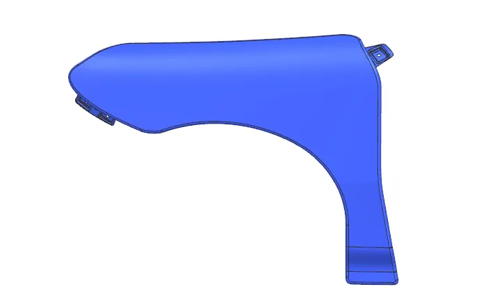
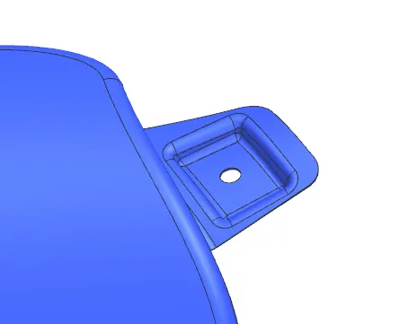
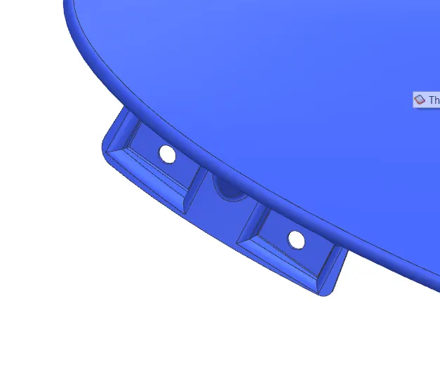
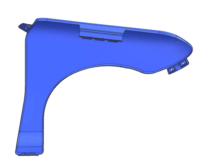
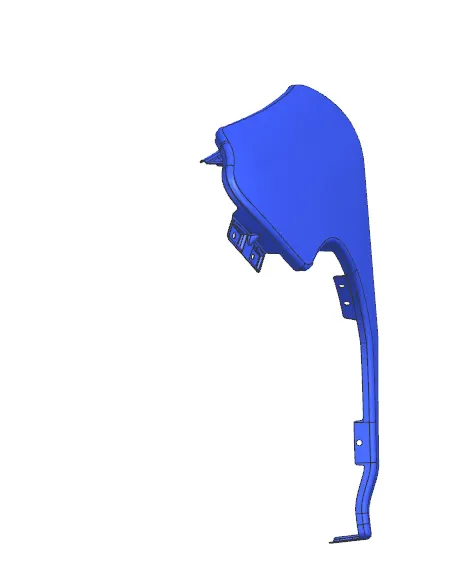
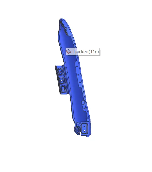
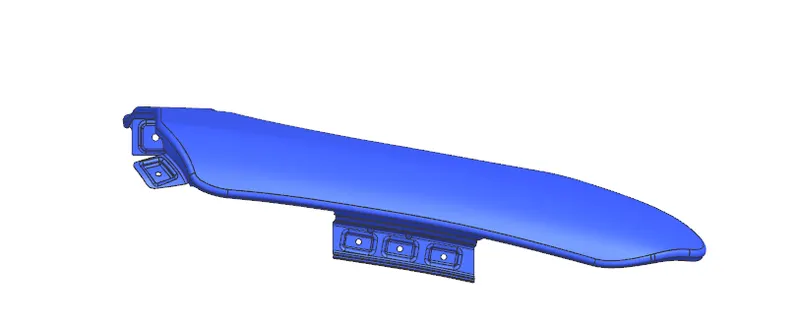
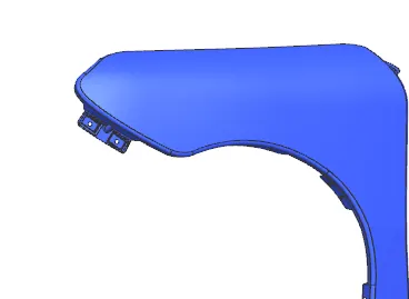
The above shown are the images of the design that we have done by using the above procedure at different views and forms.
Conclusion:
After all this we can conclude that our efforts for fender design and all the mountings have done a great appearances and results after the final part as shown above. as per the design considerations and requirments we have design the fender as shown.