Week 7 Challenge - Assembly Workbench
By: Pramod Mamillapalli
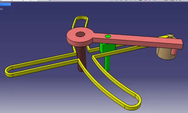
Quick Return Mechanism:
In mechanical engineering, the "quick return mechanism" refers to a mechanical system used in machines like shapers and mechanical presses. Its purpose is to enable a faster return stroke of a cutting tool or press after completing its working stroke. This mechanism is commonly used in applications where repetitive linear motions are required.
A simple example of a quick return mechanism can be found in the shaper machine. In a shaper, a cutting tool is mounted on a reciprocating ram. During the forward cutting stroke, the ram moves slowly, cutting material from the workpiece. However, during the return stroke, the ram moves rapidly back to its starting position, allowing for a quicker return and increasing the efficiency of the machine.
The primary advantage of the quick return mechanism is that it reduces the idle time of the machine, allowing for faster production rates and increased productivity. The specific design of the quick return mechanism can vary depending on the application and the machine's requirements.
Procedure:
Creating a quick return mechanism in CATIA V5 involves using the Assembly Design workbench to assemble the different components and create the desired motion. Here's a step-by-step guide on how to create a basic quick return mechanism:
Step 1: Create the Components
- Open a new CATIA V5 part file for each component of the mechanism (e.g., crank, slider, connecting rod).
- Design each component using the Part Design workbench. Ensure that the dimensions and constraints are appropriate for the quick return mechanism you want to create.
Step 2: Save the Components
- Save each component separately to your desired location.
Step 3: Create an Assembly
- Open a new Assembly Design workbench in CATIA V5.
- Go to the "Product" menu and select "New Product."
Step 4: Import Components
- In the Assembly Design workbench, go to the "File" menu and select "Import External Components."
- Browse and select the previously saved components (crank, slider, connecting rod).
Step 5: Assemble the Components
- Use the "Constraint" toolbar to assemble the components correctly. Common constraints used in a quick return mechanism are "Revolute" and "Slider."
- For example, constrain the crank to rotate around a fixed point (e.g., origin) using a "Revolute" constraint. Connect the connecting rod to the crank using another "Revolute" constraint. Then, attach the slider to the connecting rod using a "Slider" constraint.
Step 6: Define Motion
- To create the quick return mechanism's motion, you need to define the driving constraint for the crank.
- Go to the "Assembly Constraints Definition" toolbar and select "Driving Constraint."
- Select the axis or edge of the crank you want to act as the driver and define the motion type (usually "Angle" for a crank).
Step 7: Define Motion Law
- Go to the "Insert" menu, select "Motion Laws," and then choose "Law Function."
- Define a function that represents the motion of the driving constraint (crank). For a basic quick return mechanism, you can use a sinusoidal or linear function to control the crank's motion.
Step 8: Test the Mechanism
- Once the mechanism is assembled and the motion is defined, you can test the quick return motion by dragging the timeline or using the "Animate" feature in CATIA V5.
Remember that creating a quick return mechanism may involve more complex designs and additional constraints, depending on your specific requirements. It's essential to understand the mechanical principles and have a clear design concept before creating the assembly in CATIA V5.
CV Joint:
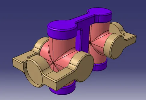
A CV joint, short for Constant Velocity joint, is a crucial component used in the drivetrain of many vehicles. Its primary function is to transfer torque from the transmission to the wheels while accommodating the up-and-down motion of the suspension system. CV joints are commonly found in front-wheel-drive (FWD) and all-wheel-drive (AWD) vehicles.
The CV joint is responsible for maintaining a constant velocity of the drive shaft regardless of the angle at which it is operating. As the wheels move up and down due to uneven road surfaces or suspension compression, the CV joint allows the drive shaft to flex and change its length without affecting the rotational speed. This capability is essential for smooth power delivery and steering control.
CV joints consist of a housing containing ball bearings or rollers, along with a set of bearings. The inner part of the joint connects to the drive shaft, while the outer part connects to the wheel hub. This setup allows the wheels to turn freely while transmitting power to them.
There are generally two main types of CV joints:
1. Rzeppa CV joint: This type of CV joint uses six ball bearings in a cage, allowing it to operate at various angles without losing efficiency. It's commonly found in most FWD vehicles.
2. Tripod CV joint: This type uses three roller bearings and is often used in outboard CV joints in FWD vehicles.
As with any mechanical component, CV joints can wear out over time due to factors like mileage, driving conditions, and lack of proper maintenance. Common signs of a failing CV joint include clicking or popping noises during turns, vibrations while driving, or torn CV boots (rubber covers protecting the joint). If the CV joint is damaged or worn out, it should be replaced promptly to ensure safe and reliable vehicle operation. Regular maintenance, such as inspecting and replacing torn CV boots, can help extend the life of the CV joints.
Procedure:
Creating a detailed 3D model of a CV joint in CATIA V5 involves several steps using the Part Design workbench. Here's a general step-by-step guide to help you get started:
Step 1: Set Up the CATIA V5 Environment
- Open CATIA V5 and create a new Part Design file.
Step 2: Sketch the Profile of the CV Joint
- Enter the Sketcher workbench by clicking on "Start Sketch" in the Part Design workbench.
- Sketch the profile of the CV joint's cross-section. The profile typically consists of an inner circle (for the shaft) and an outer profile (for the joint housing). Make sure the dimensions and constraints match the design requirements.
Step 3: Create the 3D Shape
- Exit the Sketcher workbench by clicking on "Exit Workbench."
- Use the "Pad" command from the Part Design workbench to extrude the sketch and create a 3D shape representing the CV joint's cross-section. Specify the desired depth of the joint.
Step 4: Create the Ball Bearings
- Enter the Sketcher workbench again.
- Sketch a single ball bearing's profile on a plane perpendicular to the shaft's axis.
- Use the "Pocket" command from the Part Design workbench to create a cavity based on the ball bearing sketch. Make sure to place the pocket at the correct positions on the joint's inner and outer profiles.
Step 5: Create Ball Bearings Array
- Use the "Circular Pattern" command from the Dress-Up workbench to create an array of ball bearings around the CV joint's shaft. This will distribute the ball bearings evenly around the joint's inner profile.
Step 6: Add Grooves for Ball Bearings
- Create additional sketches representing grooves or raceways on the CV joint's inner and outer profiles to accommodate the ball bearings.
- Use the "Pocket" command to create these grooves on the CV joint model.
Step 7: Create the CV Joint Housing
- Enter the Sketcher workbench again.
- Sketch the profile of the CV joint's housing around the ball bearings, ensuring the dimensions and constraints are accurate.
- Use the "Pad" command to extrude the sketch and create the CV joint housing.
Step 8: Combine the Components
- Use the "Boolean Operations" (Union) to combine the CV joint's shaft, ball bearings, and housing into a single part.
Step 9: Add Fillets and Chamfers
- Use the "Fillet" command from the Dress-Up workbench to add fillets and smooth out sharp edges on the CV joint model.
- Use the "Chamfer" command to add chamfers where needed.
Step 10: Final Adjustments
- Check the model for any errors or inconsistencies and make necessary adjustments to ensure a proper representation of the CV joint.
This process provides a basic outline for creating a CV joint in CATIA V5. Keep in mind that CV joint design can be quite complex, so depending on the level of detail and accuracy required, you might need to use advanced features and techniques in CATIA V5.
Note:
Every assembly consists of sub elements, so we have to create each sub elements separately and we have to assemble them.
Concluison:
As per the given challenge i designed the quick return mechanism and cv joint by following the procedure and steps explained in the videos in different manner just to make my hand free on this.