Week 9 - Challenge 1 - Base Bracket Design
Base Bracket Design:
What is Draft Analysis?
In CATIA V5, "Draft Analysis" refers to a tool or feature that helps you analyze and visualize the draft angles on a part's surfaces. Draft angles are angles measured between a surface and a reference plane, typically perpendicular to the parting direction in plastic injection molding or casting processes. Draft angles are crucial to ensure the smooth release of a part from its mold.
The Draft Analysis tool in CATIA V5 allows you to:
1.Visualize Draft Angles:
The tool displays different colors on the surfaces of a part to represent varying draft angles. This visual representation helps designers and engineers quickly identify areas where the draft angles might not meet the desired specifications.
2. Evaluate Draft Consistency:
By using the Draft Analysis tool, you can assess whether the draft angles across the part are consistent and within acceptable limits. This helps in preventing potential issues during manufacturing.
3. Identify Design Flaws:
Uneven or inadequate draft angles can lead to problems such as sticking in the mold, surface defects, or difficulties in ejection. The Draft Analysis tool aids in identifying such design flaws early in the design process.
4. Optimize Part Design:
Engineers and designers can make informed decisions about modifying the part geometry to achieve the required draft angles and improve manufacturability.
To use the Draft Analysis tool in CATIA V5:
1. Open the part you want to analyze in CATIA V5.
2. Go to the "Tools" menu or use the appropriate toolbar icon to access the "Draft Analysis" tool.
3. Select the surfaces or faces you want to analyze.
4. Configure the analysis settings, such as color coding for different draft angle ranges.
5. Run the analysis to visualize the draft angles on the selected surfaces.
Remember that the availability and functionality of tools can vary across different CATIA V5 versions and configurations. The tool might be named slightly differently, but the core functionality remains consistent: to help you analyze and optimize draft angles for better part manufacturability.
To perform a draft analysis in CATIA V5, you can follow these steps:
-
Open the Part: Open the part file that you want to analyze in CATIA V5.
-
Activate the "Draft Analysis" Workbench: Make sure you are in the "Part Design" workbench, and then activate the "Draft Analysis" workbench. You can do this by selecting "Start > Mechanical Design > Draft Analysis."
-
Select Surfaces: In the "Draft Analysis" workbench, you'll see the "Draft Analysis" toolbar. Use the "Select" tool from this toolbar to choose the surfaces or faces that you want to analyze for draft angles. Click on the surfaces one by one, or you can use the selection filters to select multiple surfaces at once.
-
Configure Analysis Settings: Once you've selected the surfaces, you need to configure the analysis settings. Click on the "Draft Analysis Settings" icon on the toolbar to open the settings dialog. In this dialog, you can adjust the color range for different draft angles, specify the draft angle reference plane, and set other options according to your requirements. These settings will determine how the draft angles are visualized on the surfaces.
-
Run the Analysis: After configuring the settings, close the settings dialog. Then, click on the "Run Analysis" icon on the toolbar. CATIA will analyze the selected surfaces' draft angles based on your settings and display the results.
-
View Draft Analysis Results: The analyzed surfaces will be color-coded based on the draft angles. The color legend should be displayed on the screen, showing the corresponding draft angle ranges for each color. This visualization helps you quickly identify areas with insufficient or excessive draft angles.
-
Interpret and Make Changes: Review the draft analysis results to identify any areas that require attention. If you find surfaces with improper draft angles, you may need to modify the part geometry to ensure proper mold release and manufacturability. Adjust the geometry and repeat the analysis as needed until you achieve the desired draft angles.
-
Exit the Draft Analysis Workbench: Once you're done with the analysis and any necessary modifications, you can exit the "Draft Analysis" workbench by selecting a different workbench from the CATIA interface.
Please note that the exact steps and icons might vary slightly depending on the CATIA V5 version you're using, but the general process should remain consistent. If you're unsure about specific steps or options, you can refer to the CATIA V5 documentation or user guides for more detailed instructions.
Followed Process:
Aim: To create a Base Bracket Plastic Component through a given Class A Surface and perform Draft Analysis on the final plastic component.
Objectives:
- Creation of Tooling Axis.
- Creation of Class B and Class C surface.
- Creating a solid part out of surface modelling.
- Draft Analysis of Class A surface and final plastic component.
Tool Used: CATIA V5
Introduction: In this project we are designing a base bracket using given class A surface. The approach includes creation of Class B surface keeping 3 mm thickness in mind for the complete component. The design also included Class C creation from the given parent surface.
Constraints:
- NO CHANGES IN CLASS A ARE ALLOWED.
- PART THICKNESS CANT DEVIATE BY MORE THAN ±±30%
- ALL DESIGN RULES SHOULD BE STRICTLY FOLLOWED.
- ALL SURFACES SHOULD BE CLOSED BEFORE CONVERTING TO SOLID.
- ALL FACES SHOULD MEET THE ALLOWED DRAFT REQUIREMENTS.
CLASS A: Following surface is given as the input for the component creation.
Click here to see the Surface.
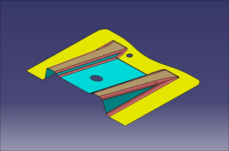
To continue with the design process first we need to find out the tooling axis for the surface and check for all the drafts using Draft Analysis tool of CATIA.
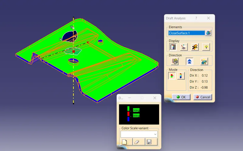
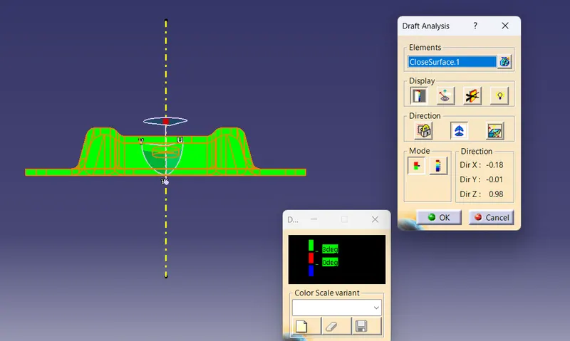
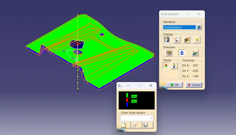
Draft Analysis for Surface A:
The analysis is done for 3degree draft. So as can be seen all the surfaces are more than 3deg.
Creating of Tooling Axis:
- Create an intersection of CLASS A surface with ZX plane and from the intersection create the tooling axis as shown below.
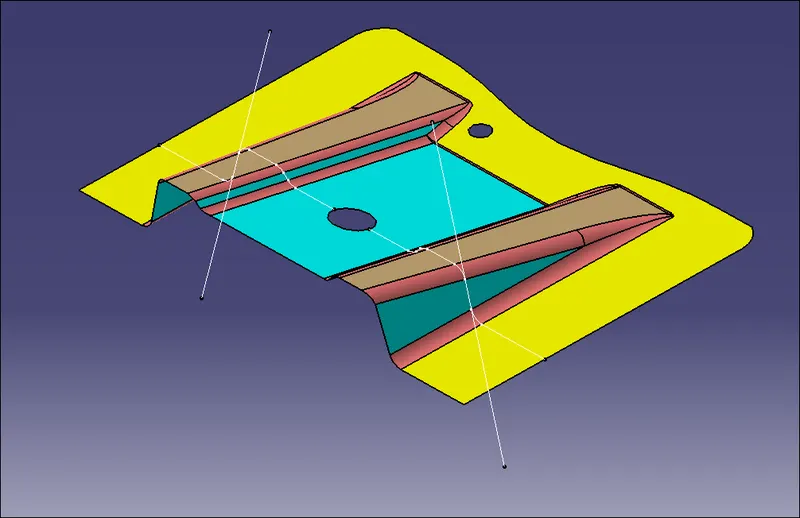
- Create a bisecting line using the lines shown above.
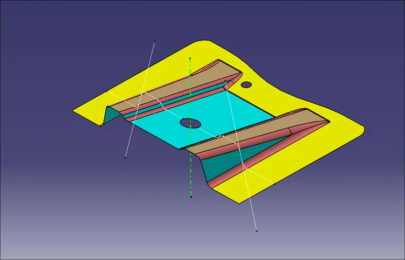
- Here, Line shown in dotted green is our tooling axis.
Creation of Class B:
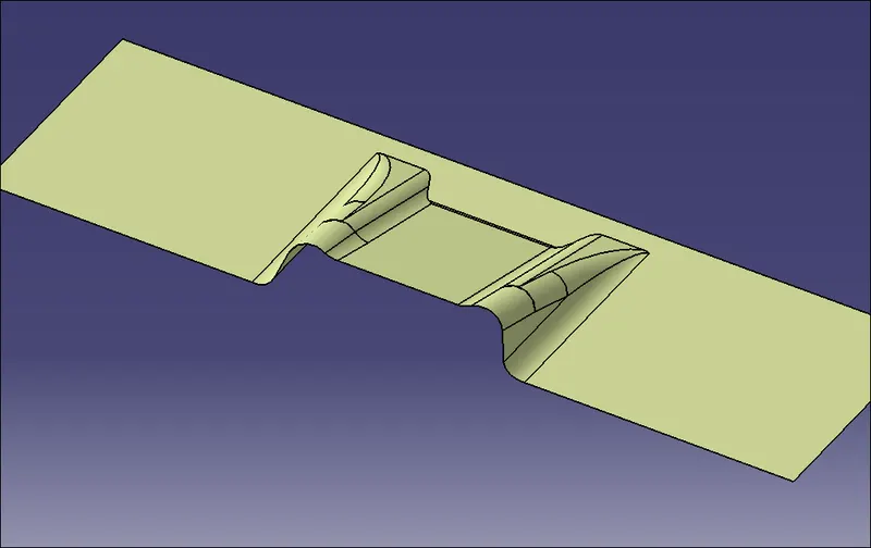
- Now for Class B creation, we have extracted surface from Class A and untrimmed them to obtain the original parent surface.
- These surfaces are then offset to the required thickness.
- After offsetting, all the surfaces are trimmed into the required shape.
- Required fillets are given to the surfaces.
Creation of Class C:
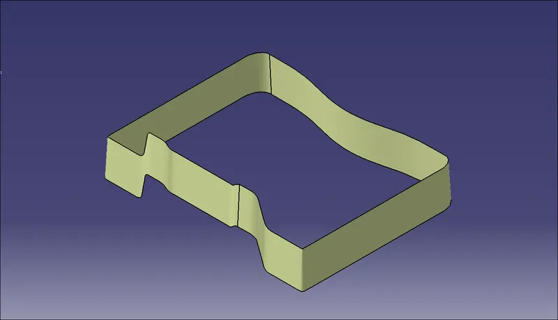
- For creating this surface we have extracted the boundry of Class A using multi-extract and then converted to smooth curve.
- Now this smooth curve is swept along the draft direction with a 3deg draft.
Final Trims:
Class A + Class C:
To make sure that there is not any open boundry between class A and class C, we have used join option to created the single body. This is done to make sure that the parting line doesn't lie between the these two surfaces.
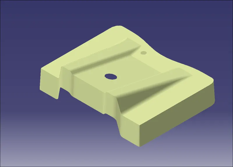
Class A + Class B + Class C:
For this we have trimmed the above shown surface with the Class B surface using trim feature.
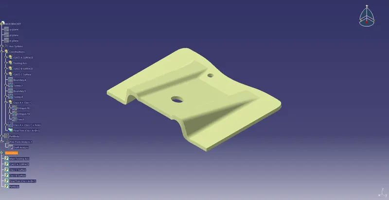
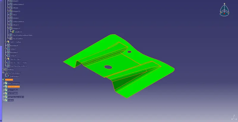
All the main features are published as can be seen in the image shown above.
Draft Analysis on the Final Component:
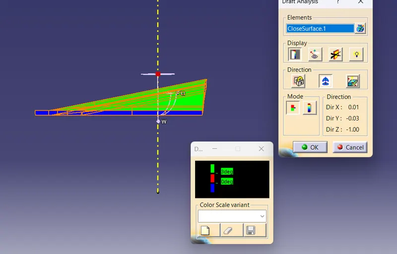
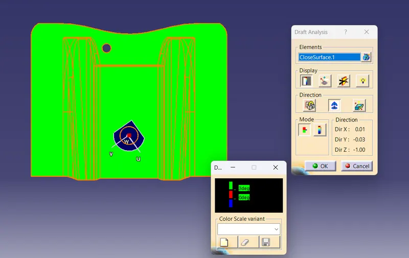
For this analysis, main tooling axis is taken draft reference.
Following results were obtained:
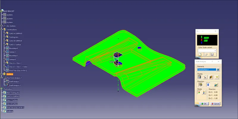
Draft Analysis foe Class A:
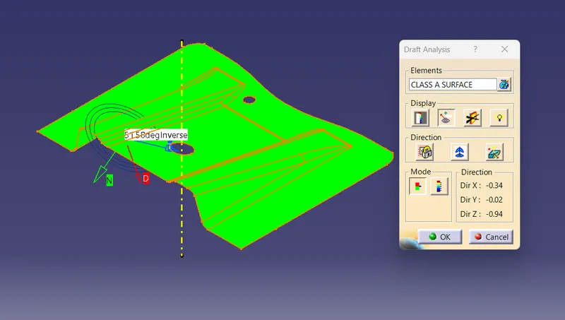
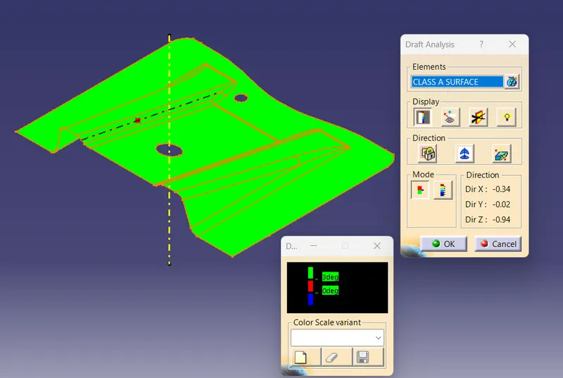
Final Part Draft Analysis: