American Chopper
Project Title: AMERICAN CHOPPER (By: Pramod Mamillapalli)
Project Objective: In this project we are going to design the full 3d model of an American chopper by using the solid works tools for designing and rendering.
Introduction: Here we are partly not able to design a 3d model of an American chopper directly in precise manner, so we have to design each and every part individually then at the end will combine together to form an assembly of an American chopper. Next step we have to do the lights and camera setup to make a final 3d render.
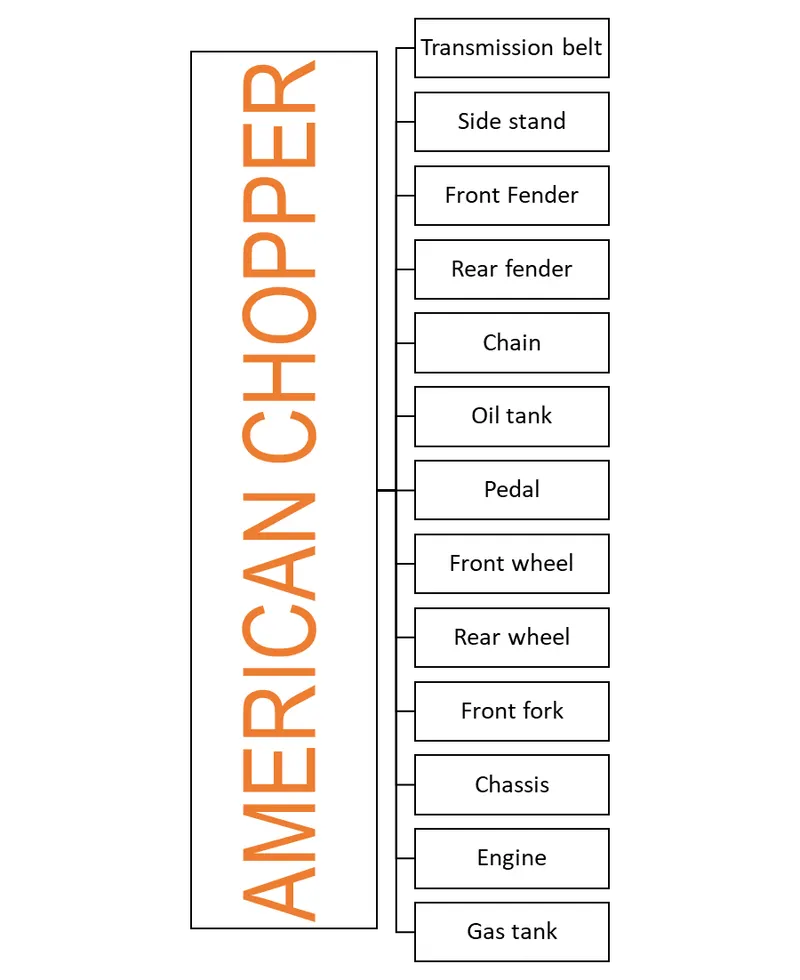
Approach: let me explain the process of designing with the help of images and flow chart,
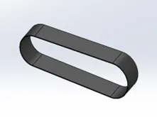
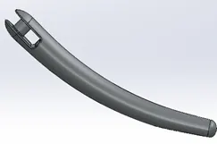
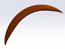
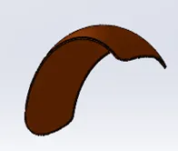
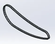
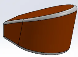
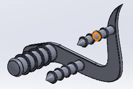
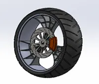
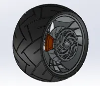
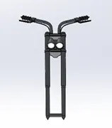
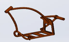
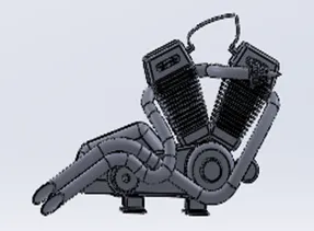
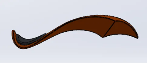
The above shown images are references of individual parts designed for American chopper.
(Transmission belt, side stand, front fender, rear fender, chain, oil tank, pedal, front wheel, rear wheel, front fork, chassis, engine, and gas tank).
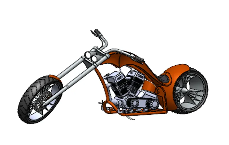
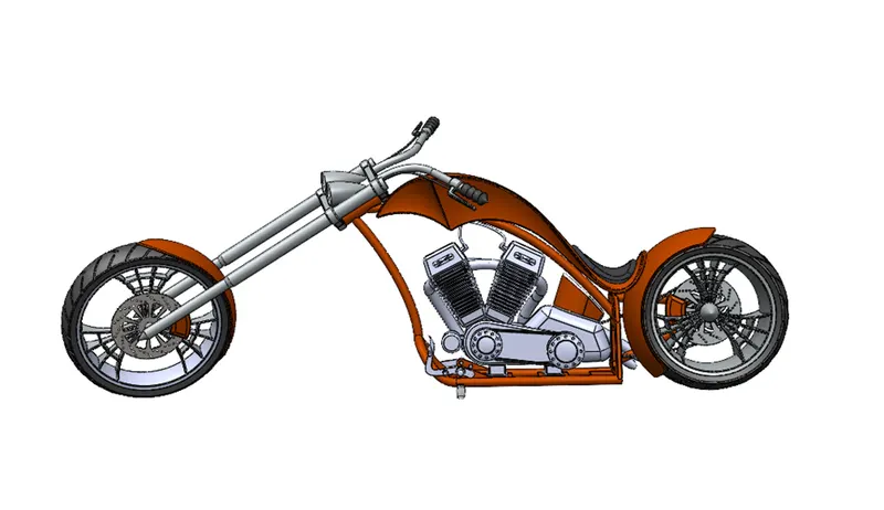
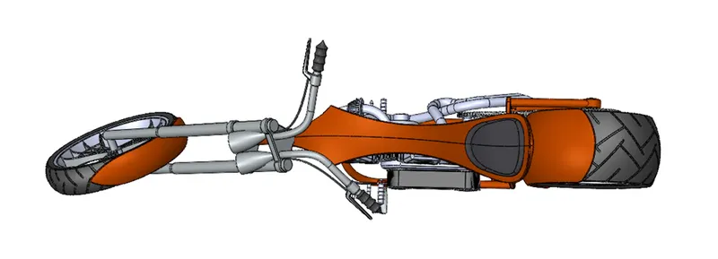
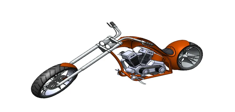
Main assembly 3d model of American chopper by assembling the all-designed components.
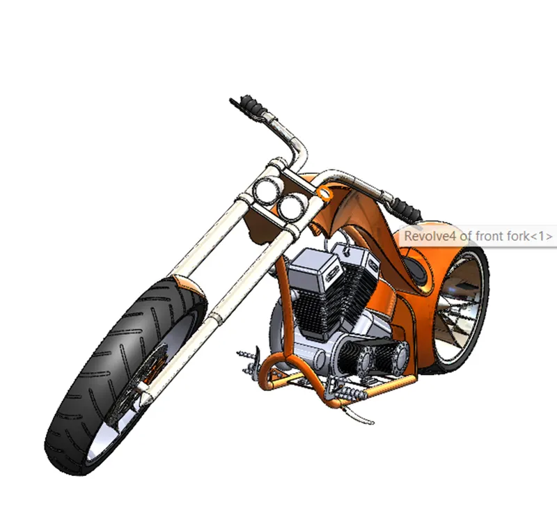
We have to firstly design the individual models of our American chopper parts as sub-assemblies as described above by creating a base template of solid works chopper which helps you to make the creation ease. The exact dimensions and measurements will be available in the part files attached along with this report. Make sure that every design must be fully defined and fully constrained to get ride of errors while assembling. After creating the sub-assemblies we need to create a assemble file and then open all the part file at once to make assembling easy and quick. After that we have to take chassis first and make it fixed along with the help of three dimensional planes using mates feature, then we can add and start assembling the parts one by one for building the chopper. Here we also have to be careful in giving the proper contact between the face of assemble to make it fully constrained. After this we have to add decals, scenes, lights and camera for the final render as shown below.
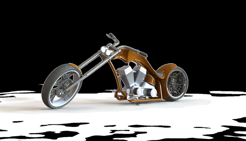
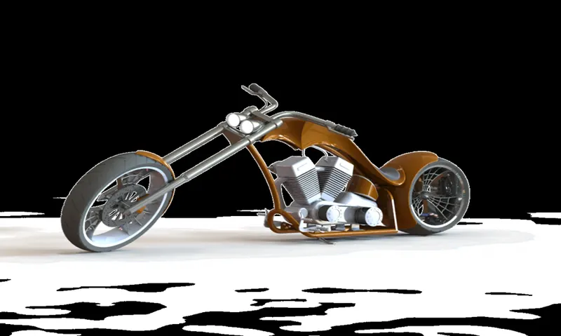
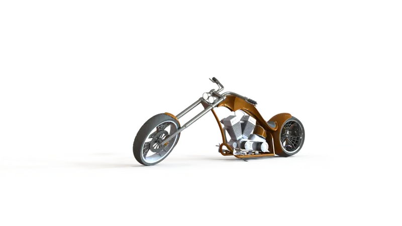
Final renders 3d image of American Chopper.
Description:
Note: Repeated features are skipped Because it is already explained in above bodies.
1.Transmission belt:
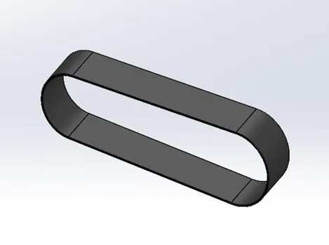
In this transmission belt we need to select the one of the planes to create a new sketch,
Line: line tool is used to create the lines which are tangent to both side of arcs.
Three-point arc: This arc tool is used to create the arcs both ends for both the tangential lines.
Boss extrude: This feature is used to project the 2d design sketch to 3d extract.
Fillet: This feature is helpful to make sharp edges and corners so soft and realistic.
Appearances: This is a tool which actually helps to enhance the part into very much realistic manner by applying colours and materials,
- Side stand or kick stand:
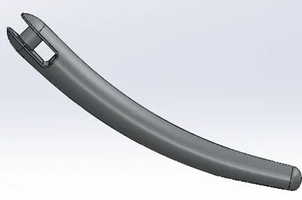
Ellipse: this feature is used to draw an ellipse for the outer shape of and cross section of the side stand.
Spline: It helps to create a track for doing loft between two ellipses with desired curves and bends.
Rectangle: rectangle is used to cut the lofted elliptical part for giving place for fitting into chassis.
Circle: Circle is used to create a circular area to describe the bolt fitting between chassis and kick stand.
Dome: This feature is used to create a rounded surface at the ends of lofted ellipses.
Split: It is used for split some desired material from the sketch.
Fillet: Helps to make edges and corners smooth and curvy.
Cut extrude: This is a very handy feature to remove the drawn cross section from the 3d model.
Loft: This is a very useful feature to combine two ellipse or circles with different sizes with the help of path with desired shapes and cross sections.
Boss extrude: This feature is used to make 2d sketch into a stretched 3d model.
Centre point line: This is a handy tool to draw a line from the desired point describing as its centre of the drawn with equal distance.
3.Front and Rear Fenders:
Three-point arc: This feature helps to create a arc with reference of its centre point for creating a mud guard for the wheels.
Revolve: This feature is used to revolve the desired sketch around its centre point.
Split and Fillet: (same as explained in previous part).
4.Chain:
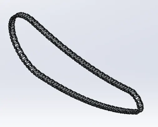
Curve pattern: This is a very important feature to assign a drawn pattern in a desired path as the link travel in a path as shown in the figure.
Mirror: It is a very handy feature to make the sketch or feature project to the opposite side with the help of centre datum.
Slot: This feature helps to create an offset of a two parallel sketches with the help of its both mid points through dragging them.
- Oil Tank and Pedal:
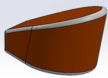
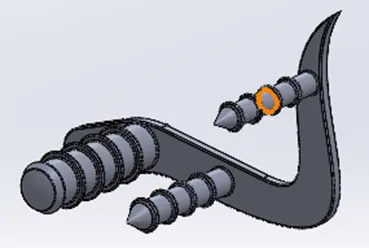
Chamfer: This feature helps to cut the sharp edged into taper.
Linear offset pattern: This feature is similar as circular pattern but the difference is this pattern follows the line with the help of offsetting the number of patterns between some desired gaps or distance.
Combine: This is rarely used feature in this chopper series which helps to combine the number of bodies into one.
Shell: This one helps us with doing some hallow space in the designed solid structure.
Smart dimension: This feature helps to measure of give certain measurements for the sketch.
6.Front and Rear wheels:
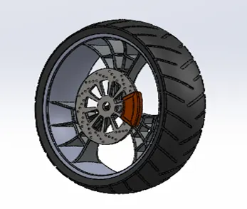
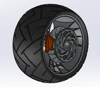
Cut Revolve: Very unique feature to create unique models, it actually make the cuts in revolved or circular surface. (as shown in side the rims).
7.Front fork and Chassis:
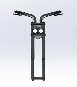
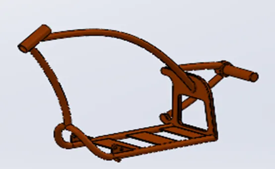
Sweep: This feature is used to projects the sketch as a solid body along the path selected.
Reference plane: This is very handy tool mostly used in complex designs by add planes as our own to draw a sketch where ever needed. Also helps to view the body as reference.
Convert entities: If you want the proper reference same as the previously drawn sketch for saving time and efforts then you can use convert entities tool for taking as a primary reference for the sketch.
- Engine and Gas tank:
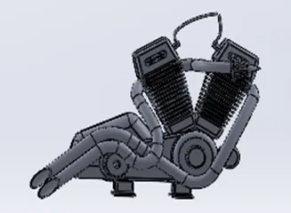
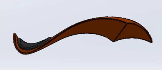
Projected Curve: A projected curve is typically used either in sweeps and lofts as path or guide curve. There are two types of projected curves: Sketch on Sketch: Use two sketches to make a single curve. Sketch on surface: Use a sketch to project on a surface.
Composite curve: You can create composite curves by combining curves, sketch geometry, and model edges into a single curve.
Assembly:
Front view:
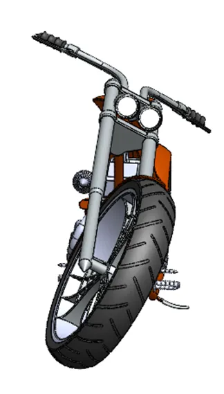
Side view:
Top view:
Isometric view:
Camera view:
Rendered Images:
Conclusion:
The purpose this project is to learn how to design the assemblies and how to assemble the parts into one. As we discuss the project is successfully initiated with the knowledge of designing the bigger assemblies and brief discussion about the tools and features that where to use the perfect features, finally it ends up with adding some realistic features like lights, cameras, decals and renders.
-------------------------------------------------------------------------------------------------------------------------------------