Week 9 - Challenge 3 - Bumper
Draft Analysis:
In CATIA V5, as in any CAD software, a draft angle refers to the angle between a surface on a part and a reference direction, typically perpendicular to the parting line or mold split direction. Draft angles are an essential consideration in part design for manufacturing processes like injection molding, casting, and stamping.
Draft angles are important because they enable smooth part ejection from molds and reduce the likelihood of surface defects, such as scratches, marks, or deformation. Without sufficient draft angles, parts might get stuck in the mold, leading to production issues and increased costs.
In CATIA V5, draft angles are often evaluated and managed using the "Draft Analysis" tool, which allows designers and engineers to analyze the draft angles on a part's surfaces and identify areas that may require adjustments.
To define the draft angle in CATIA V5:
- Open the part you're working on.
- Identify the reference direction, usually the mold split direction.
- Measure the angle between the reference direction and the surface you want to evaluate.
It's important to ensure that your design meets the required draft angle specifications for the manufacturing process you intend to use. The actual draft angle value depends on factors like the material being used, the part's geometry, the type of manufacturing process, and the specific requirements of the manufacturer.
By maintaining proper draft angles in your design, you can help ensure a smoother production process, reduce the risk of defects, and improve the overall quality of the manufactured parts
Steps for Draft Analysis:
-
Open the Part: Start by opening the part that you want to analyze for draft angles in CATIA V5.
-
Access the Draft Analysis Tool: There are multiple ways to access the Draft Analysis tool:
- Go to the "Analysis" menu, then navigate to "Draft Analysis."
- Look for the "Draft Analysis" icon on the Analysis toolbar and click on it.
-
Select Surfaces: After activating the Draft Analysis tool, you'll need to select the surfaces or faces you want to analyze for draft angles. You can use the "Select" button within the Draft Analysis dialog box to pick the surfaces.
-
Configure Analysis Settings: Once you've selected the surfaces, you can configure the analysis settings:
- Choose the method for calculating the draft angles (e.g., between surface normals and a reference direction).
- Specify the color scheme for visualizing different draft angle ranges. Typically, surfaces with adequate draft angles are displayed in one color, while those with insufficient draft are shown in another color.
-
Run the Analysis: After configuring the settings, click the "Apply" or "OK" button within the Draft Analysis dialog box to run the analysis. The selected surfaces will be color-coded based on their draft angles according to the settings you've defined.
-
Interpret the Results: Study the color-coded surfaces. Surfaces in the desired draft angle range will be displayed in the color you specified, while surfaces with inadequate draft angles will be displayed in the contrasting color. This visual representation helps you identify areas that might need adjustments to ensure proper part release during manufacturing processes.
-
Make Design Adjustments: If you identify surfaces with draft angle issues, you can modify the part design accordingly. You might need to adjust the geometry of those surfaces to achieve the required draft angles while maintaining the intended design.
-
Save and Review: Save your work and review the part to ensure that draft angle issues have been addressed. You can iterate through these steps as needed to fine-tune the design.
Tooling Direction:
In CATIA V5 and similar CAD software, the term "tooling direction" refers to the direction in which a tool or mold component will be moved during a manufacturing process, such as injection molding or casting. It's a critical aspect of designing parts for manufacturability, especially when dealing with complex shapes that require molds or dies for production.
The tooling direction determines how a part is extracted from a mold, die, or tool without causing damage to the part itself or the tooling. The tooling direction is closely related to the concept of draft angles, which are the angles built into the part's design to facilitate its smooth release from the mold or tooling.
Key points about tooling direction:
1. Mold Split or Parting Line: The tooling direction often corresponds to the parting line or mold split line, which is the imaginary plane that divides the mold into two halves. The mold opens along this plane to release the manufactured part.
2. Draft Angles: Draft angles are typically incorporated into the part's design to ensure that the part can be easily removed from the mold without sticking. The tooling direction determines the angle at which the mold halves will separate.
3. Undercuts and Complex Features: For parts with complex geometries or undercuts (features that prevent a straight pull), multiple mold components or sliding mechanisms might be used. The tooling direction for these components should allow for their smooth movement and the successful ejection of the part.
4. Manufacturing Processes: Tooling direction is crucial for processes like injection molding, where melted material is injected into a mold cavity, and the part must be ejected once it solidifies. It's also important in processes like die casting, where molten metal is poured into a mold cavity.
5. Design for Manufacturability: Designing with consideration for the tooling direction and draft angles ensures that the manufactured parts will have consistent quality, reduced defects, and efficient production cycles.
In summary, the tooling direction in CATIA V5 and other CAD software is the orientation along which mold components or tooling will move to extract a part from the mold or tool. Proper consideration of tooling direction and draft angles is essential for achieving successful and cost-effective manufacturing processes.
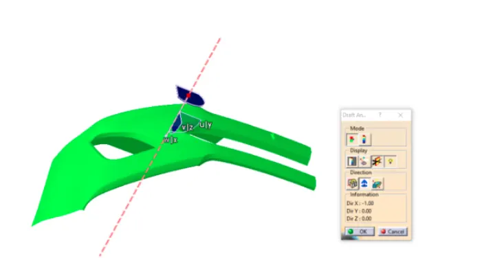
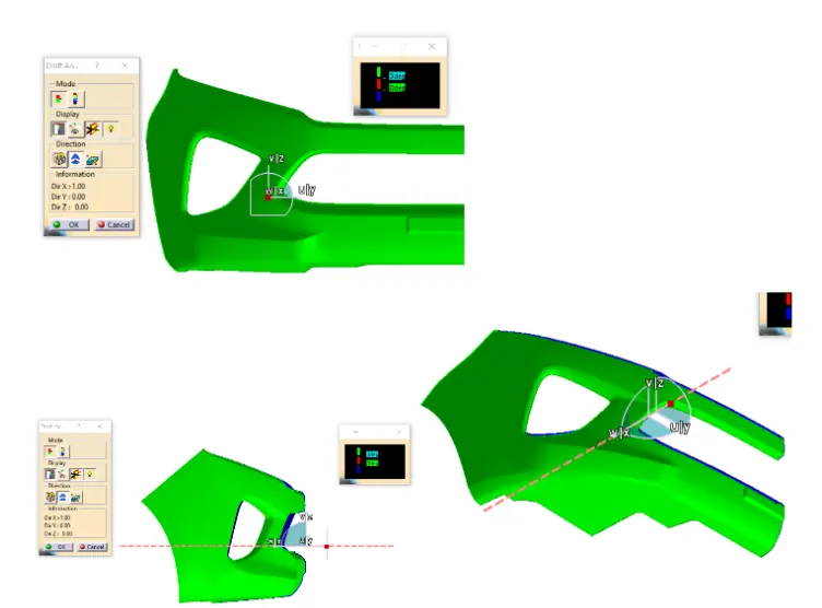
Draft Analysis For Cass A:
Conclusion:
The Draft analysis of the component showed that the component is feasible to be molded without any issues. Thus it satisfies all design and manufacturing criterias needed for a proper part. This concludes the report of Design of Bumper Body.