Week 10 - Challenge 3 - Door Trim Lower with Engineering Features
AIM
To study the creation of locator and heat stakes.
OBJECTIVE
Create the Door Trim Lower Plastic component through the given Class-A surface. To begin with, the tooling axis for the given Class-A Surface should be created meeting the requirements of the draft angle and at the end perform the Draft analysis on the model.
THEORY
Heat Stakes design :-
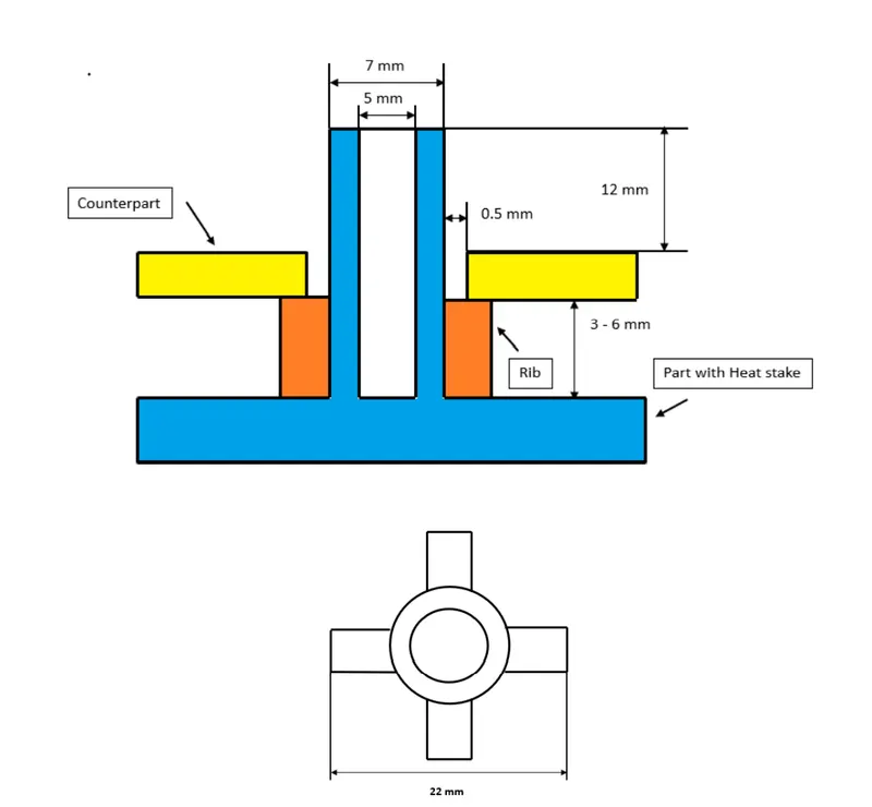
figure 1. heat stakes design
- Counter Part Thickness - Will be given as input
- Component Wall Thickness - Will be given as input
- Length of the Rib - 22 mm
- Height of the Ribs - 3 mm to 6 mm
- Inner Diameter of Heat Stake (d) - 5 mm
- Outer Diameter of Heat Stake (d) - 7 mm
- Minimum clearance between heat stake and counterpart - 0.5 mm
- Height of the Heat stake - Depends on the rib height and counter-part thickness
- Minimum fillet of Heat Stakes - 0.25 mm
- Minimum Draft Angle of Heat Stakes - 0.5 degrees
Locator :-
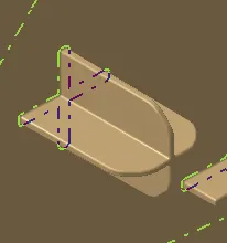
figure 2. four way locator
- Height of the locators should be 1 mm (or) 2 mm greater than the heat stakes
- Thickness, fillet and draft angle are of same as rib design rules.
- Ideal Chamfer value - 3 mm x 45 degrees
- Ideal length of the locators - 15 mm
TOOLING AXIS
Here the tooling axis is created parallel to the Y axis because in this direction we can see the whole surface and surface is not planar. That is create the point on surface and create a line at that point using point and direciton option. Where as direction as XZ plane. Bisecting line method for creating a tooling axis is suitable for symmetric surfaces.
DRAFT ANALYSIS OF CLASS A SURFACE
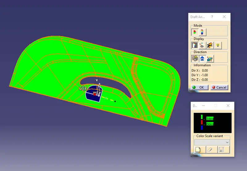
figure 3. class A draft analysis
Here draft analysis carried for class A surface with respect to tooling axis. Here colour code used is a green colour indicating that the draft is 3 degree or above. The red colour indicates that the draft is 0 degree and the blue colour indicates that the draft is minus value. From draft analysis we can see that green colour is all over the surface and hence it is suitable for further process because it follows optimum draft.
DRAFT ANALYSIS OF A MODEL
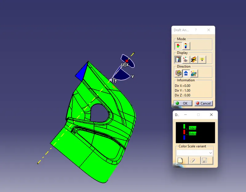
figure 4. door trim draft analysis
Here we need to check the draft of door trim, locator and heat stakes along tooling axis. First check the for the door trim, we have to set colour for the draft analysis with minimum draft of 3 degrees. Here colour code used is a green colour indicating that the draft is 3 degree or above. The red colour indicates that the draft is 0 degree and the blue colour indicates that the draft is minus value. From draft analysis we can see that green color over the surface of the door trim. That is the door trim follows optimum draft of 3 degrees.
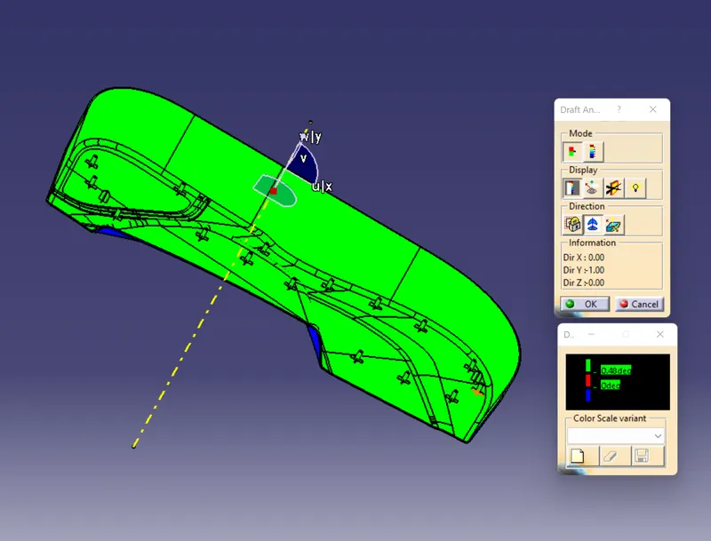
figure 5. draft analysis with 0.48 degrees
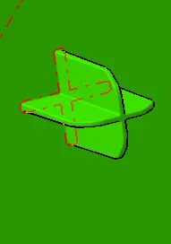
figure 7. draft analysis of locator with 0.48 degrees
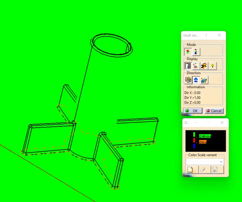
figure 8. draft analysis of heat stakes with 0.48 degrees.
Next we have to check the draft of locator and heat stakes along tooling axis. Then set the colour code for the draft analysis with minimum draft of 0.48. Here colour code used is a green colour indicating that the draft is 0.48 degree or above. The red colour indicates that the draft is 0 degree and the blue colour indicates that the draft is minus value. From draft analysis we can see that green colour over the surface of the locator and heat stakes. That is the locator and heat stakes follows optimum draft of 0.48 degrees.
MODEL VIEWS
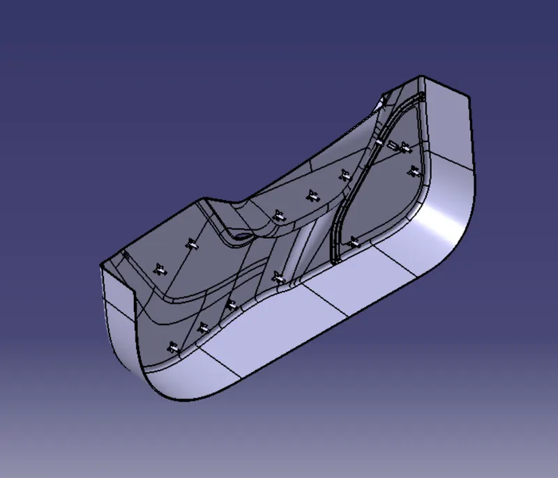
figure 9. isometric views
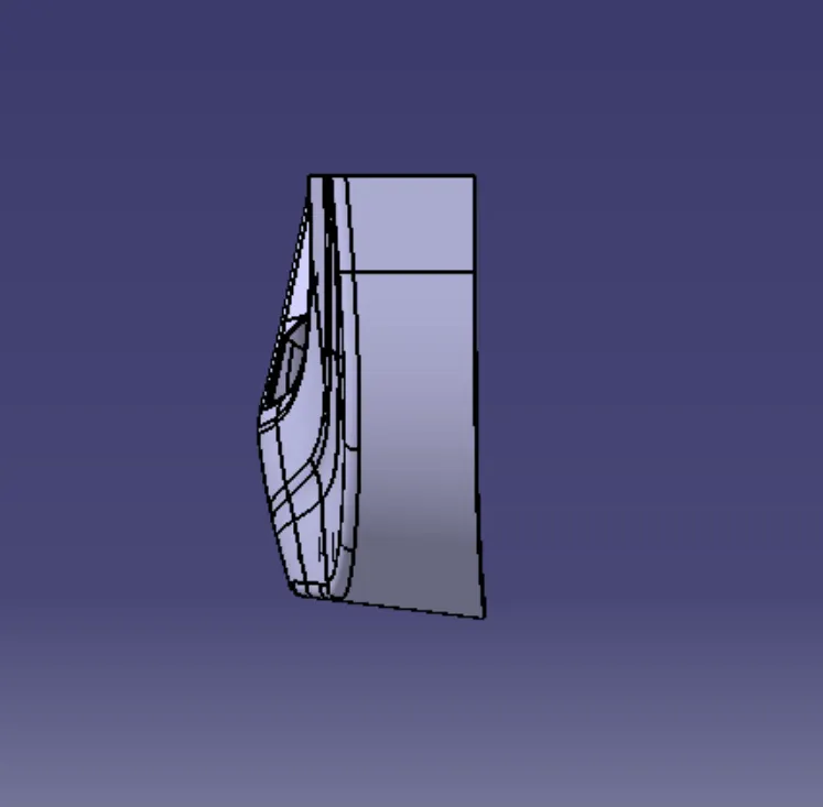
figure 10. front view
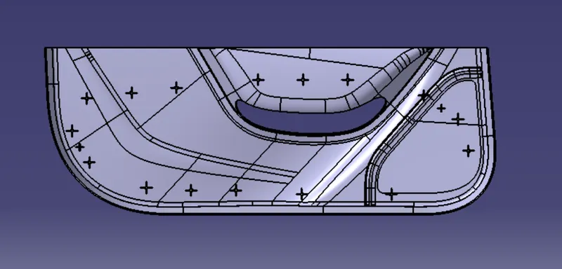
figure 11. right side view
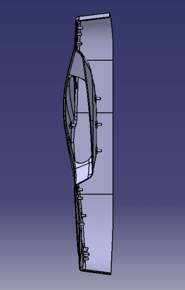
figure 12. top view
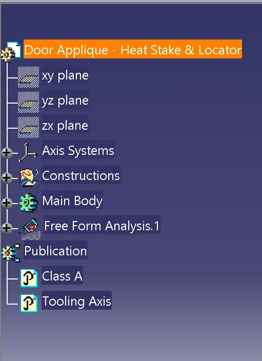
figure 13. tree structure
OVERALL REPORTS SUMMARY:
REPORT 1:
Title: Draft Analysis and Tooling Axis Creation in CATIA V5
Abstract: This report presents a step-by-step guide for performing draft analysis and tooling axis creation in CATIA V5. Draft analysis is a crucial step in assessing the manufacturability of a part, while tooling axis creation is essential for generating accurate toolpaths for manufacturing.
1. Introduction: Draft analysis and tooling axis creation are fundamental aspects of the design-to-manufacturing process. Draft analysis evaluates the angles and surfaces of a part, ensuring proper mold release and minimizing defects. Tooling axis creation establishes the orientation for machining processes, enabling efficient manufacturing.
2. Draft Analysis: Draft analysis is primarily used in plastic part design and mold making. It involves checking the angles of a part's surfaces with respect to a specified pull direction. CATIA V5 provides tools to analyze draft angles and optimize the part design for successful molding.
Steps for Draft Analysis:
- Open the CATIA V5 part document.
- Navigate to the "Analysis" toolbar.
- Click on the "Draft Analysis" icon.
- Select the reference direction for draft analysis.
- Adjust the draft analysis parameters, including angle tolerances.
- CATIA V5 highlights the regions violating the specified draft angles.
3. Tooling Axis Creation: Tooling axis creation involves defining the orientation of the part for machining processes. It ensures that the toolpaths are generated accurately and efficiently.
Steps for Tooling Axis Creation:
- Open the CATIA V5 part document.
- Ensure the part is properly constrained and oriented in the assembly if applicable.
- Navigate to the "Manufacturing" or "Digital Mock-Up" workbench.
- Click on the "New Tooling Axis" icon.
- Select the surfaces or features that will serve as references for the tooling axis.
- Define the direction for the tooling axis by specifying a vector or selecting references.
- Adjust any additional parameters, such as clearance planes and angular limits.
- CATIA V5 generates the tooling axis and displays it graphically.
4. Best Practices:
- Draft Analysis: Maintain consistent draft angles to ensure proper ejection and minimize defects during molding.
- Tooling Axis Creation: Choose reference surfaces that align with the intended manufacturing process. Consider accessibility and interference with other components.
5. Conclusion: Draft analysis and tooling axis creation are vital steps in the design and manufacturing workflow. CATIA V5 offers powerful tools for analyzing draft angles and generating accurate tooling axes, contributing to efficient manufacturing processes and high-quality end products.
REPORT 2:
Creating a Tooling Axis Using the Bisecting Method in CATIA V5:
The Bisecting method is commonly used to create a tooling axis for machining operations. It involves selecting two reference surfaces or features and generating a tooling axis that bisects the angle formed by these references. This method is particularly useful when the desired tooling axis lies between two distinct surfaces.
Steps for Creating a Tooling Axis Using the Bisecting Method:
-
Open the Part Document: Launch CATIA V5 and open the part document in which you want to create the tooling axis.
-
Switch to the Manufacturing Workbench: If you are not already in the Manufacturing workbench, switch to it to access the machining-related tools.
-
Start Tooling Axis Creation:
- Click on the "New Tooling Axis" icon from the toolbar. This icon usually resembles a coordinate system or an arrow.
- Alternatively, you can navigate to the "Insert" menu, choose "Manufacturing Feature," and select "Tooling Axis."
-
Select Reference Surfaces:
- In the "Tooling Axis Definition" dialog box that appears, you will have the option to select two reference surfaces or features.
- Choose the first surface by clicking on it in the graphics area.
- Choose the second surface by clicking on it as well. These surfaces will define the angle bisected by the tooling axis.
-
Define the Direction:
- After selecting the two reference surfaces, CATIA V5 will display a preview of the tooling axis that bisects the angle between the surfaces.
- You may have options to further refine the tooling axis direction. This might involve specifying a vector or selecting additional references to guide the axis direction.
-
Adjust Additional Parameters:
- Depending on the specific requirements of your machining process, you might need to adjust parameters such as clearance planes, angular limits, and axis extension.
-
Confirm and Generate:
- Review the preview of the tooling axis and the associated parameters.
- Once you are satisfied, click "OK" or a similar confirmation button. CATIA V5 will create the tooling axis based on the bisecting method.
-
Visualize the Tooling Axis:
- CATIA V5 will display the generated tooling axis as a graphical representation in the graphics area.
- You can adjust the display properties and visibility of the tooling axis as needed.
Tips:
- Ensure that the selected reference surfaces are suitable for defining the desired tooling axis. These surfaces should accurately represent the machining orientation you want to achieve.
- Always consider the machining process and accessibility when selecting the reference surfaces for the bisecting method.
Conclusion: Creating a tooling axis using the Bisecting method in CATIA V5 is a powerful technique that allows you to accurately define the machining orientation for efficient manufacturing. By selecting appropriate reference surfaces and following the steps outlined above, you can create tooling axes that align with your machining requirements.
CONCLUSION
Creation of locator and heat stakes are studied.