Final Project: Electric Rickshaw modelling
OBJECTIVE - To Create a detailed MATLAB model of an electric rickshaw (three wheel passenger vehicle) as per the given details:
AIM -
a). Rear wheels driven by PM brushed type motor.
b). To Assume efficiency points of motor controller and motor.
c). To Make an excel sheet of all input and assumed data .
THEORY -
E - Rickshaw -
Electric rickshaws (also known as electric tuk-tuks or e-rickshaws or toto or e-tricycles) have been becoming more popular in some cities since 2008 as an alternative to auto rickshaw and pulled rickshaws because of their low fuel cost, and less human effort compared to pulled rickshaws. They are being widely accepted as an alternative to Petrol/Diesel/CNG auto rickshaws. They are three-wheelers powered by an electric motor ranging from 650 to 1400 Watts. They are mostly manufactured in India and China, only a few other countries manufacture these vehicles. Battery-run rickshaws could be a low-emitter complementary transport for the low-income people, who suffer most from a lack of transport facility, if introduced in a systematic manner according to experts.
About E- Rickshaw (Mahindra TREO)-
Mahindra Treo is a revolutionary new range of electric autos, e-rickshaw and cargo version. Powered by the advanced Lithium-ion technology, Mahindra Treo offers higher savings, superior ride quality and best in-class interior space. Ride the change with Mahindra Treo for a better tomorrow!
FEATURES -
1). Unmached Savings -
Low running cost of only 50 paise per km, leading to savings of up to ₹ 45 000.00 every year in fuel cost*.
2). Torque and Acceleration -
With 42 Nm torque Treo offers best-in-segment acceleration of 0-20 km/h in 2.3 s which makes driving an enjoyable experience.
3).Greadability-
Mahindra Treo’s high gradeability of 12.7 degree makes it easy to climb slopes & flyovers which is the best-in-segment.
Specification -
1).Battery -
- Battery Type And Voltage - Lithium ion ,48V.
- Battery Capacity (Installed) - kWh , 7.37.
- Charging Time 0-100% @Standard Conditions , 3h 50 min .
2).Drivetrain -
- Peak Power - KW - 8.
- Peak Torque - Nm - 42 .
- Transmission Type - Direct Drive .
Suspension And Breaks -
- Suspension Front - Helical Spring + Dampener + Hydraulic Shock Absorber.
- Suspension - Rear - Rigid Axle with Leaf Sprig.
- Brakes - Front/Rear - Hydraulic .
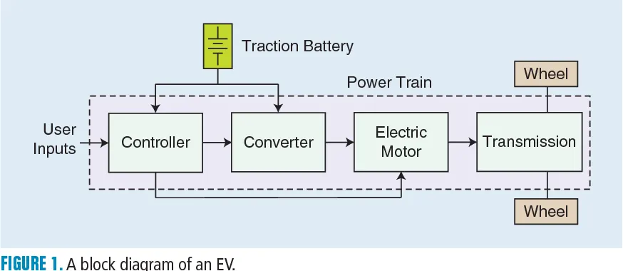
Block Diagram -
Simulink Model Of An Electric Rickshaw -
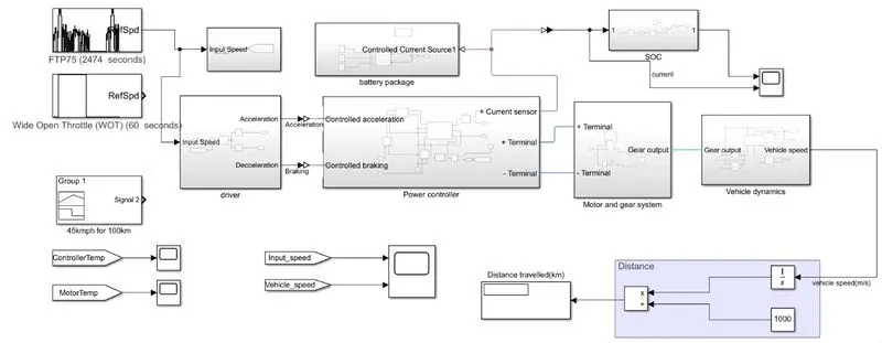
Subsystems -
1). Vehicle Dynamics subsystem -
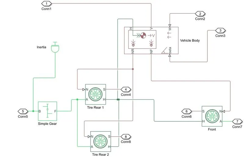
Blocks Used -
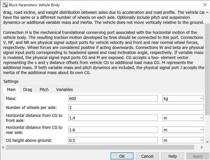
a). Vehicle Body Block -
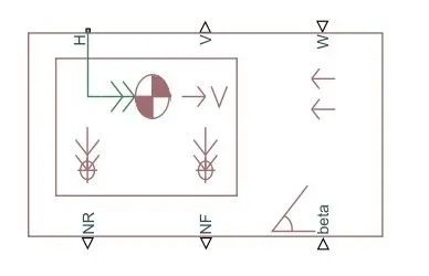
Represents a two-axle vehicle body in longitudinal motion. The block accounts for body mass, aerodynamic drag, road incline, and weight distribution between axles due to acceleration and road profile. The vehicle can have the same or a different number of wheels on each axle. Optionally include pitch and suspension dynamics or additional variable mass and inertia. The vehicle does not move vertically relative to the ground.
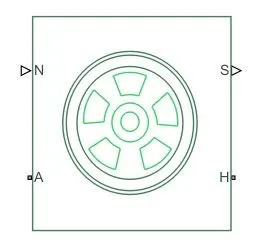
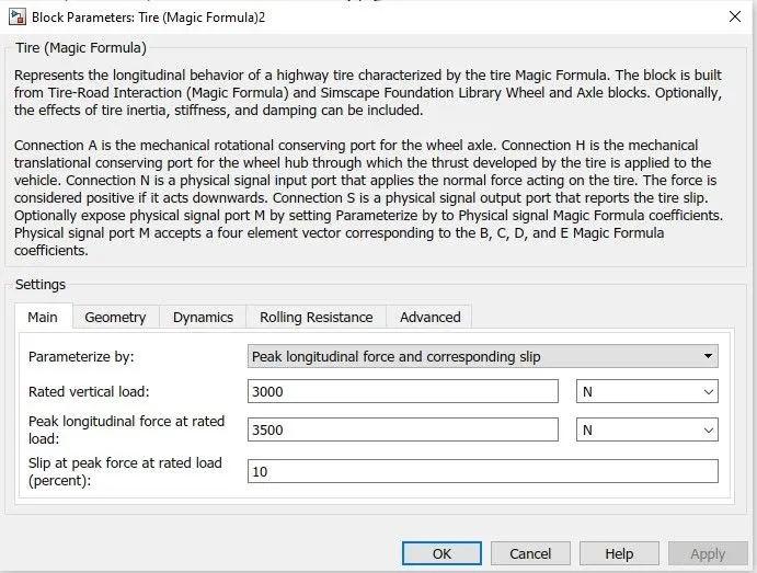
a). Tire Block -
Represents the longitudinal behavior of a highway tire characterized by the tire Magic Formula. The block is built from Tire-Road Interaction (Magic Formula) and Simscape Foundation Library Wheel and Axle blocks. Optionally, the effects of tire inertia, stiffness, and damping can be included.
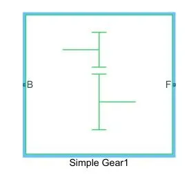
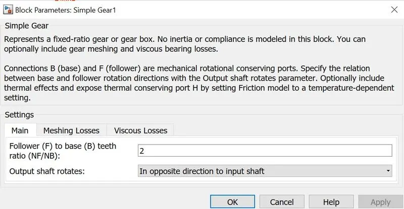
c). Simple Gear -
Represents a fixed-ratio gear or gear box. No inertia or compliance is modeled in this block. We can optionally include gear meshing and viscous bearing losses.
2).Motor and Gear System Block Subsystem -
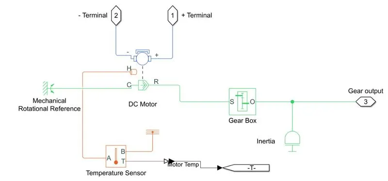
Blocks Used -
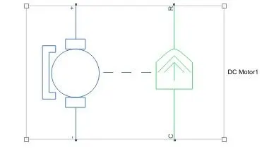
a). DC Motor Block -
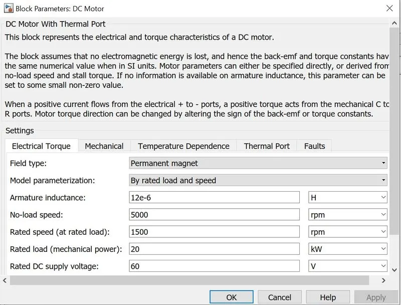
This block represents the electrical and torque characteristics of a DC motor.
The block assumes that no electromagnetic energy is lost, and hence the back-emf and torque constants have the same numerical value when in SI units. Motor parameters can either be specified directly, or derived from no-load speed and stall torque. If no information is available on armature inductance, this parameter can be set to some small non-zero value.
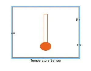
b). Temperature Sensor Block -
This block measures temperature in a thermal network. There is no heat flow through the sensor. The physical signal port T reports the temperature difference across the sensor. The measurement is positive when the temperature at port A is greater than the temperature at port B.
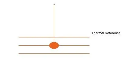
c). Thermal Reference Block -
This block represents a reference point in a thermal network where the temperature is equal to absolute zero.
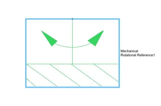
d).Mechanical Rotational Reference Block -
This block represents a mechanical rotational reference point, that is, a frame or a ground. Use it to connect mechanical rotational ports that are rigidly affixed to the frame (ground).
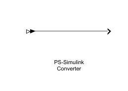
e). PS Converter Block -
Converts the input Physical Signal to a Simulink output signal.
The unit expression in 'Output signal unit' parameter must match or be commensurate with the unit of the Physical Signal and determines the conversion from the Physical Signal to the Simulink output signal.
3). Power Controller Block Subsystem -
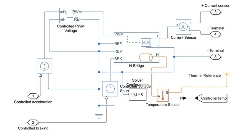
Blocks Explanation -
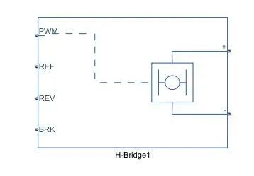
a). H- Bridge Block -
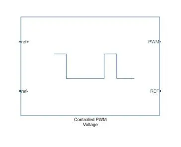
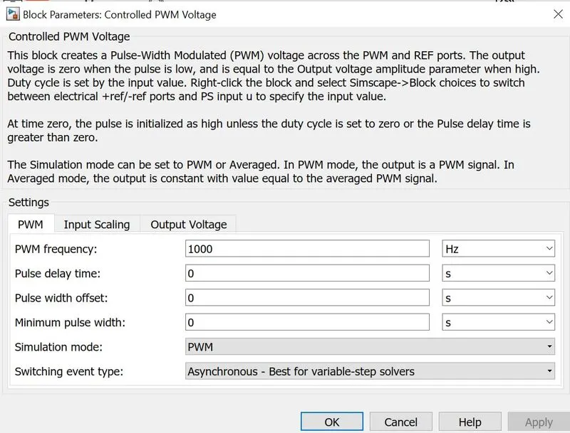
This block represents an H-bridge motor drive. The block can be driven by the Controlled PWM Voltage block in PWM or Averaged mode. In PWM mode, the motor is powered if the PWM port voltage is above the Enable threshold voltage. In Averaged mode, the PWM port voltage divided by the PWM signal amplitude parameter defines the ratio of the on-time to the PWM period. Using this ratio and assumptions about the load, the block applies an average voltage to the load that achieves the correct average load current. The Simulation mode parameter value must be the same for the Controlled PWM Voltage and H-Bridge blocks.
b). Controlled PWM Voltage -
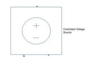
c). Controlled Voltage Source -
The block represents an ideal voltage source that is powerful enough to maintain the specified voltage at its output regardless of the current passing through it. The output voltage is V = Vs, where Vs is the numerical value presented at the physical signal port.
d). Current Sensor -
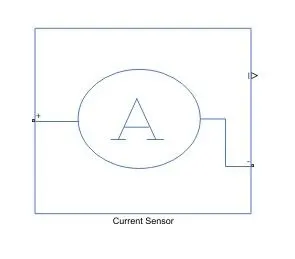
The block represents an ideal current sensor, that is, a device that converts current measured in any electrical branch into a physical signal proportional to the current.
Connections + and - are conserving electrical ports through which the sensor is inserted into the circuit. Connection I is a physical signal port that outputs current value.
e). Solver Configuration Block -

The Solver Configuration block specifies the solver parameters that our model needs before we can begin simulation.
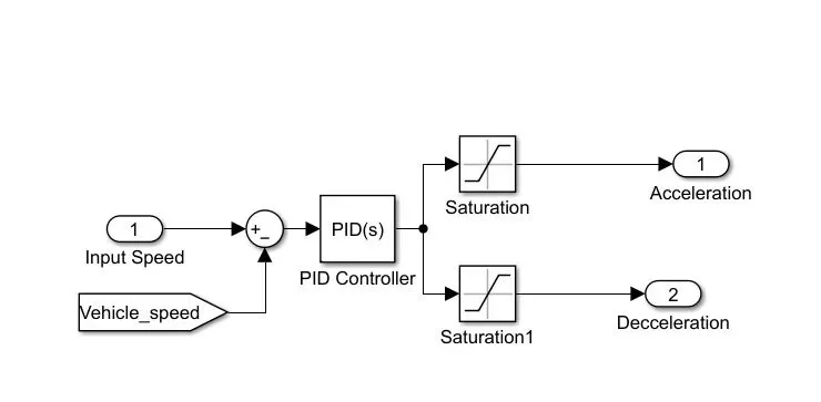
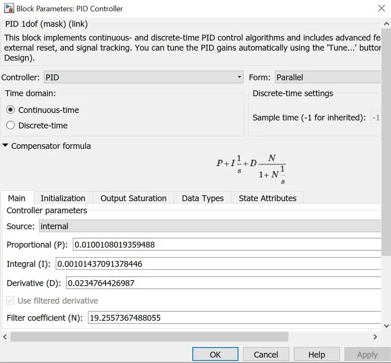
4). PID Controller Block Subsystem -
Blocks Used -
a). Saturation Block -
The Saturation block produces an output signal that is the value of the input signal bounded to the upper and lower saturation values. The upper and lower limits are specified by the parameters Upper limit and Lower Limit.

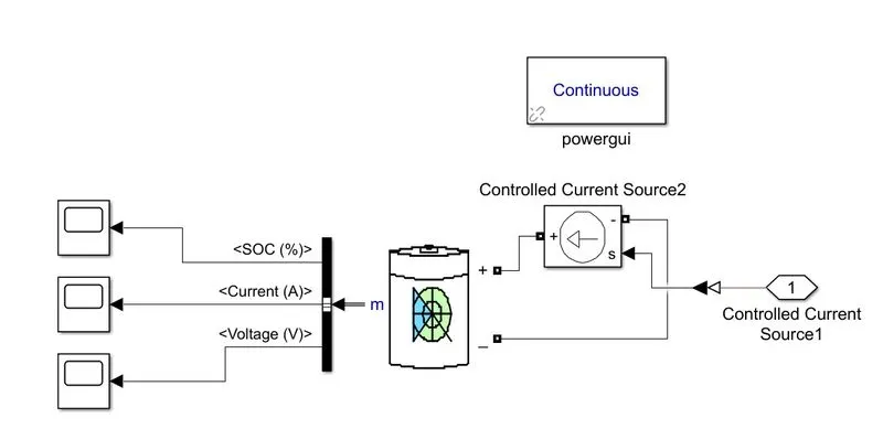
5). Battery Subsystem -
Blocks Used -
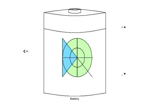
a). Battery -
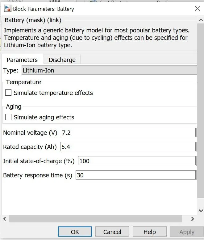
Implements a generic battery model for most popular battery types. Temperature and aging (due to cycling) effects can be specified for Lithium-Ion battery type.
Block Parameter -
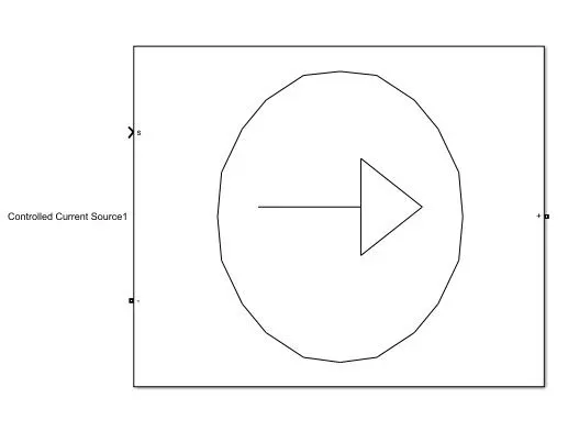
b).Controlled Current Source -
Converts the Simulink input signal into an equivalent current source. The generated current is driven by the input signal of the block.
c). Powergui Block -
Set simulation type, simulation parameters, and preferences.
6). SOC Subsystem -
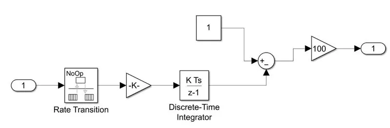
Blocks Used -
a).Rate Transition Block -

The Rate Transition block transfers data from the output of a block operating at one rate to the input of a block operating at a different rate. Use the block parameters to trade data integrity and deterministic transfer for faster response or lower memory requirements.
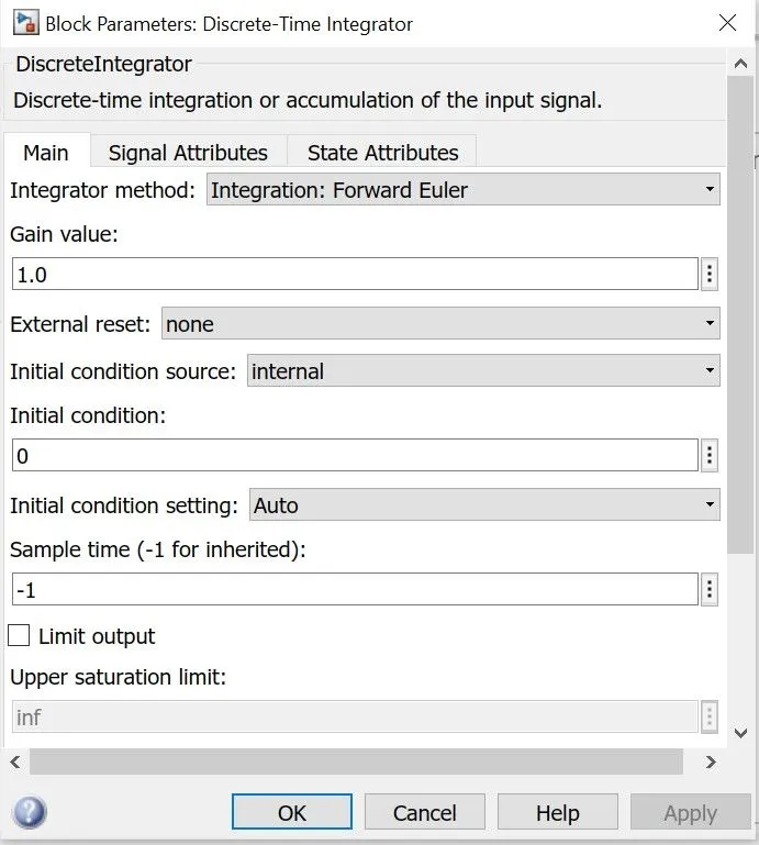
b). Discrete Time Integer Block -

Use the Discrete-Time Integrator block in place of the Integrator block to create a purely discrete model. With the Discrete-Time Integrator block, we can:
-
Define initial conditions on the block dialog box or as input to the block.
-
Define an input gain (K) value.
-
Output the block state.
-
Define upper and lower limits on the integral.
-
Reset the state with an additional reset input.
RESULTS -
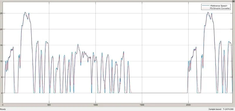
1).For FTP75 Drive Cycle-
Following are the output obtained after running the Simulation -
Conclusion -
- From the above graph it is concluded that the Reference Speed is Approximately following the Drive Cycle .
a). Controller Temperature Output -
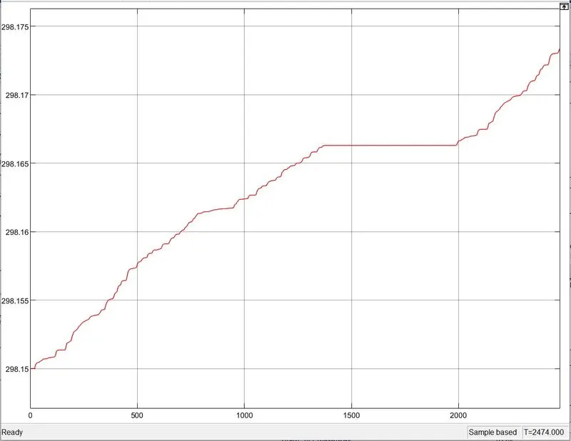
Conclusion -
The temperature of controller increases to 298 degree celcius .
b). Motor Temperature Output -
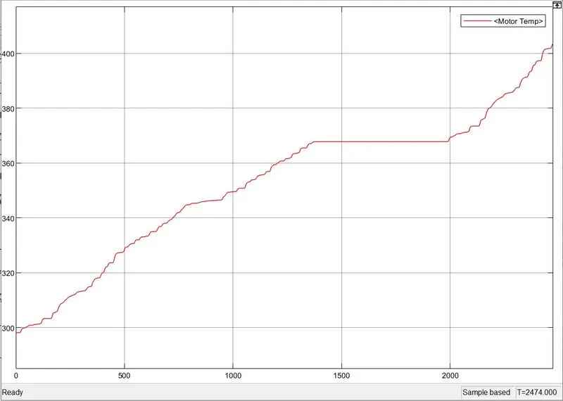
Conclusion -
Temperature of motor has been increased from 300 degree celcius to 370 degree celcius.
SIMULINK Model For Signal Builder Block -
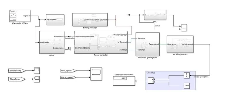
Creating The Signals for 100 km distance at constant speed driving at 45kmph.
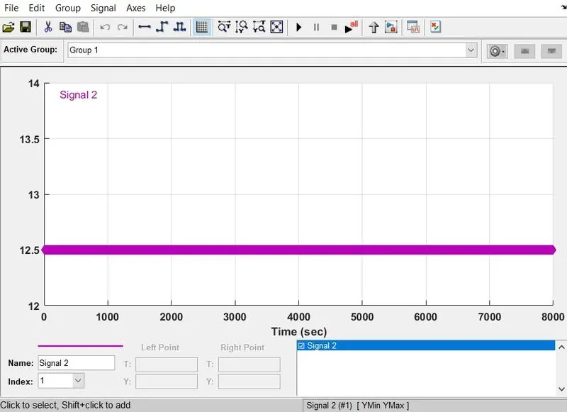
Note -
In the above graph the speed of the vehicle is converted into m/s from kmph and also the time in second .
RESULTS-
a). For Signal Builder Block Output -
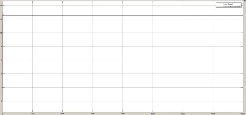
Conclusion -
- In the above graph input speed is following the ps signal converter speed which is satisfying our requirement.
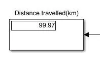
- Total Distance covered by vehicle is 99.97 km which satisfying the given condition .
b). Controller Temperature -
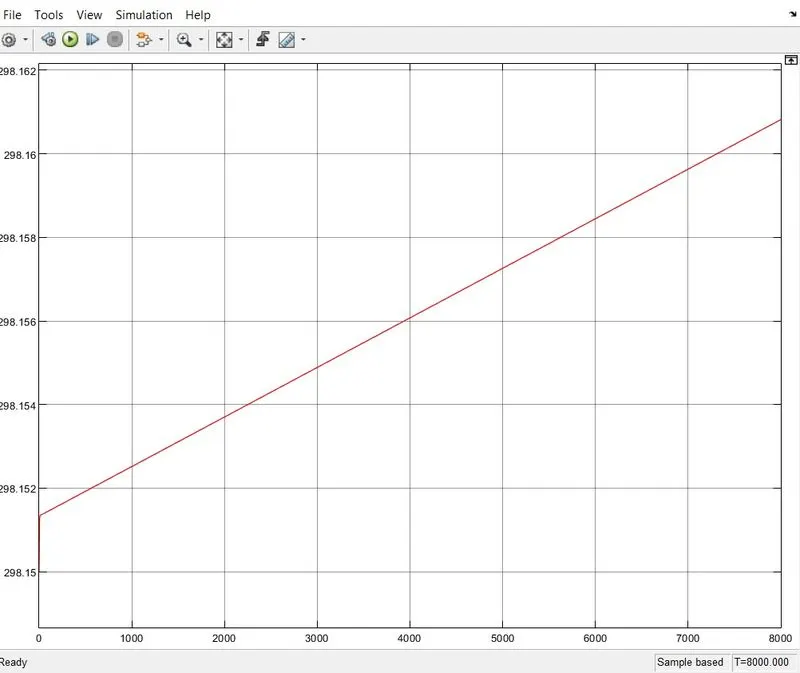
Conclusion -
As we can see from the above graph the temperature of Controller rises as the our simulink run time increases.
Motor Temperature -
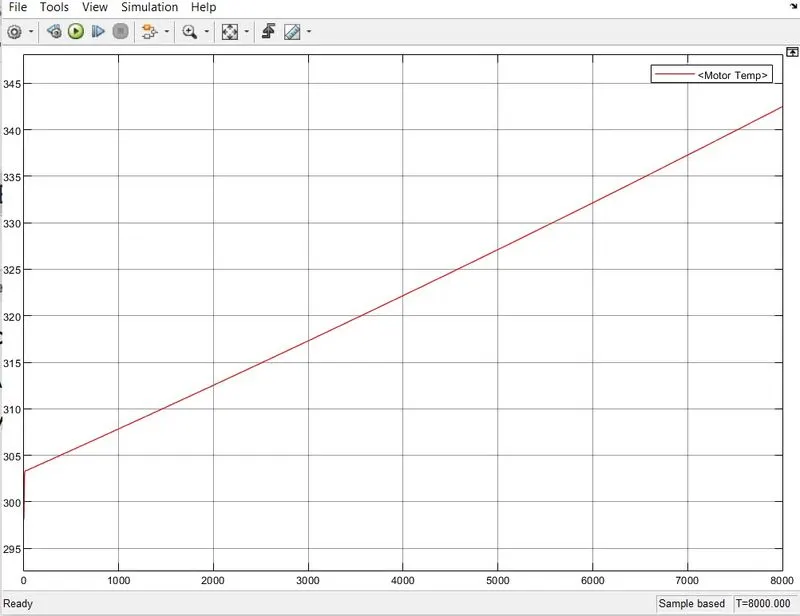
Conclusion -
The temperature of motor rises from 304 degree celsius and it going upto 343 degree celcius .
c). SOC Result -
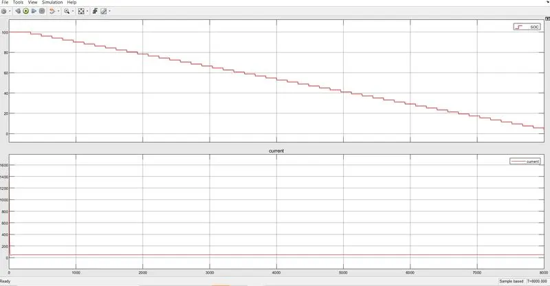
Conclusion -
- As we can see from the above graph that SOC of battery initially was 100% but it has been degraded to 10% as the vehicle runs continously.
- We also see that at some point battery has also charged as regenerative braking is applied.
- Initially the when the battery was fully charged it was carrying the high current, but when the battery started discharging the current values also decreases
Final Report Of Project -
- The MATLAB Model of electric rickshaw has been created .
- Permanent Magnet Brushed type DC motor is used to run the vehicle.
- Li-ion battery has been used so the demand of Required Power to run the motor will fullfilled.
- Variation in Temperature of Motor and Controller is successfully recorded.
- I have assume that the Natural heat transfer is used in Motor and Controller for the coooling purpose .
- Results was also recorded for FTP75 Drive cycle.
- Results was also recorded for the self made drive cycle by using signal builder block .