Week 7 State of charge estimation
AIM - To study about the State Of Charge (SOC) Estimation .
OBJECTIVES -
- Run the provided link for design and test of lithium ion battery management algorithm.
- Simulate the 3 test cases from harness dashboard and write a detailed report on the results.
- What is coulomb counting? Refer to the above model and explain how BMS implements coulomb counting for SOC estimation ?
THEORY -
State Of Charge (SOC) -
- The state of charge (SOC) of a cell denotes the capacity that is currently available as a function of the rated capacity.
- The value of the SOC varies between 0% and 100%.
- If the SOC is 100%, then the cell is said to be fully charged, whereas a SOC of 0% indicates that the cell is completely discharged.
- In practical applications, the SOC is not allowed to go beyond 50% and therefore the cell is recharged when the SOC reaches 50%.
- Similarly, as a cell starts aging, the maximum SOC starts decreasing. This means that for an aged cell, a 100% SOC would be equivalent to a 75%–80% SOC of a new cell.
Simulating the 3 test cases from harness dashboard -
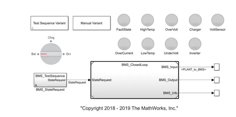
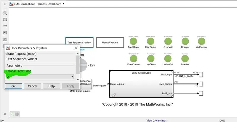
Simulink Model Of Harness Dashboard Downloaded From the given link -
Applying The Test Case Sequence 1 -
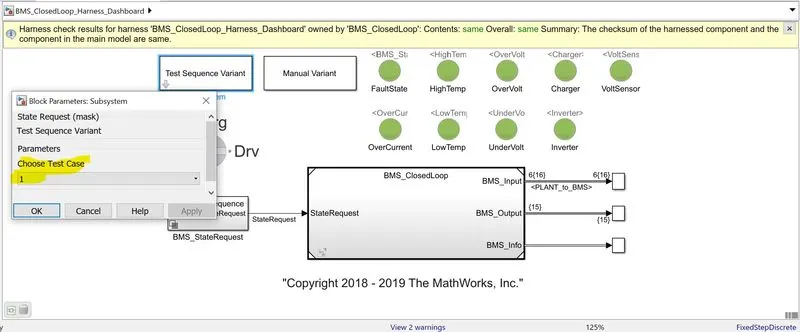
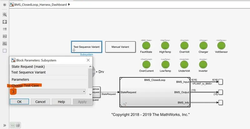
After running the simulink we can see that dashboard shows there is no Errors and Fault as all the signal are green in colour .
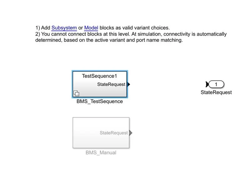
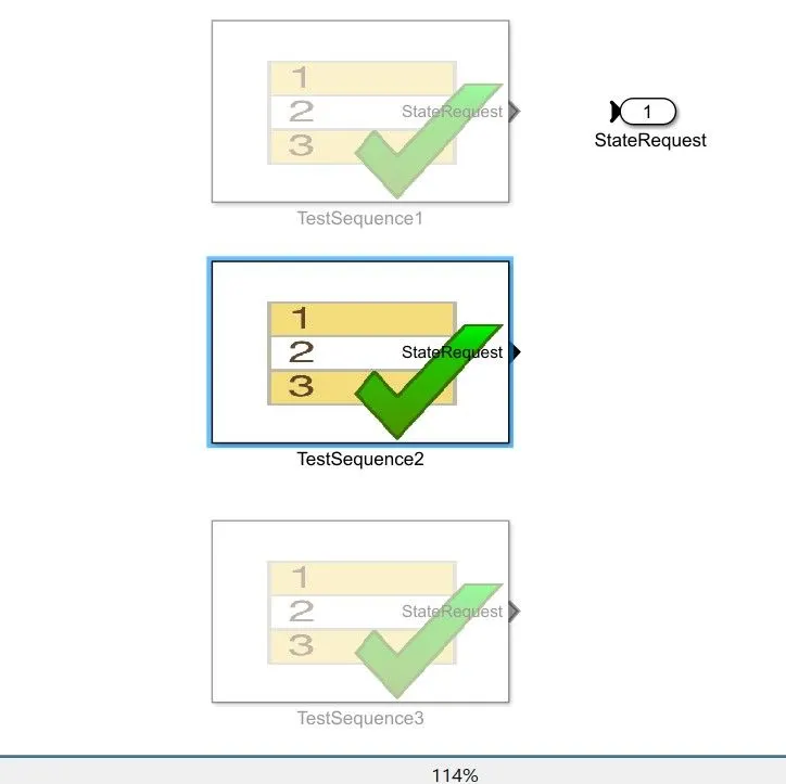
Now if we click on "BMS_stateRequest" .Following System open up and we hae to select "BMS-TestSequence".
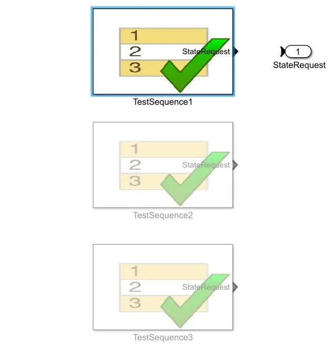
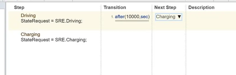
- Driving
- Charging
- Standby
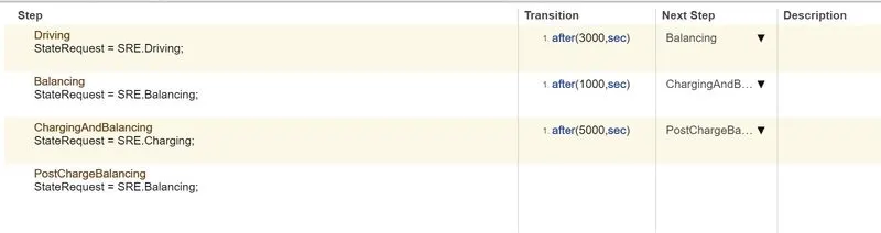
- When Simulation begins, initially the vehicle is in driving state and SOC will decrease for this time period.
- After the time period of 3000 sec ,next step is balancing mode and the vehicle is in standby condition.
- After another 1000 sec , the vehicle is in charging phase and the battery SOC increases to 100%.
- The next phase is the Post Charging phase in which vehicle will again goes for the standbby mode.
Scope Result 1 -
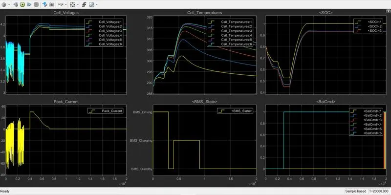
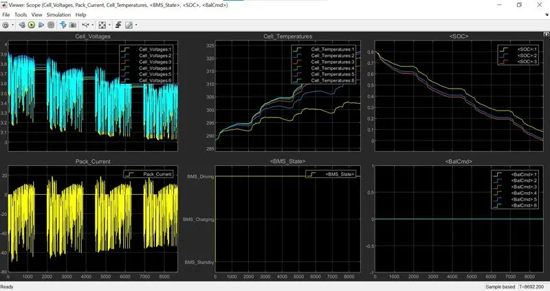
After Running the simulation we get the following result -
Conclusion From The Result -
- During charging the battery pack voltage increase upto 4.2V .
- Current value has been fall down to 15 A when charging .
- The cell temperature increases during the driving and charging cycle and starts faling of in stand by mode .
- The SOC drop to less than 50% after the driving cycle and than later put into charging untill SOC reaches 100%.
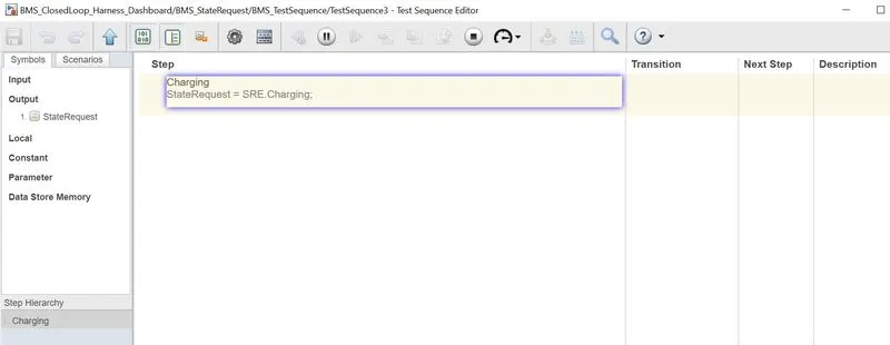
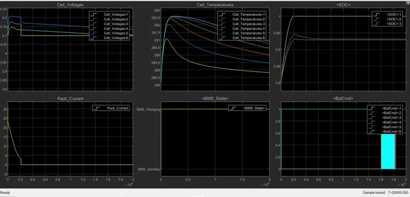
- As the battery is charging the maximum value of Voltage is 4.2V .
- Current value decreases from its maximum value 30 A to 0 A.
- There is variation in temperature values can be seen .
- Maximum value of SOC is obtained 100% as only charging of battery taking place also there is no Fault occurs.
3). Coulomb Counting - Coulomb counting involves measuring the amount of current flowing into or out of the battery.
Coulomb Counting Method -
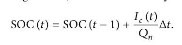
The Coulomb counting method measures the discharging current of a battery and integrates the discharging current over time in order to estimate SOC . Coulomb counting method is done to estimate the SOC(t) , which is estimated from the discharging current I(t) , and previously estimated SOC values . SOC(t-1) is calculated by the following equation:

But there are several factors that affect the accuracy of Coulomb counting method including temperature, battery history, discharge current, and cycle life .
Modified Coulomb Counting Method -
To improve the Coulomb counting method, a new technique called modified Coulomb counting method is proposed. The modified Coulomb counting method uses the corrected current to improve the accuracy of estimation.
The corrected current is the function of discharging current. There is a quadratic relationship between the corrected current and discharging current of battery. By practice of experimental data, corrected current is calculated by the following form:

where k2 ,k1 and k0 are constant values obtained from the practice experimental data.
In modified Coulomb counting method, SOC is calculated by the following equation:
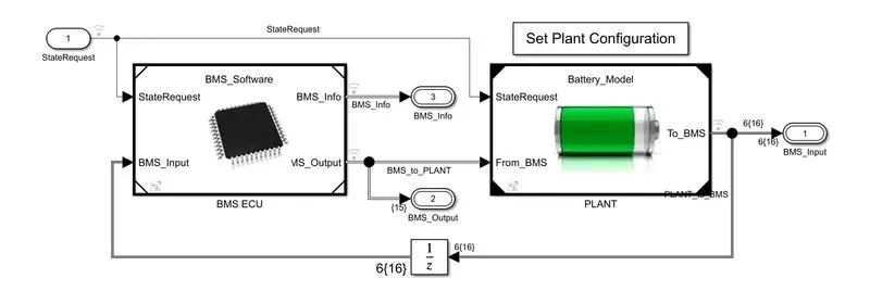 Now , opening the BMS ECU Subsystem -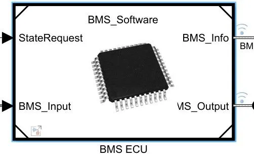
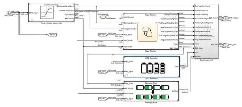
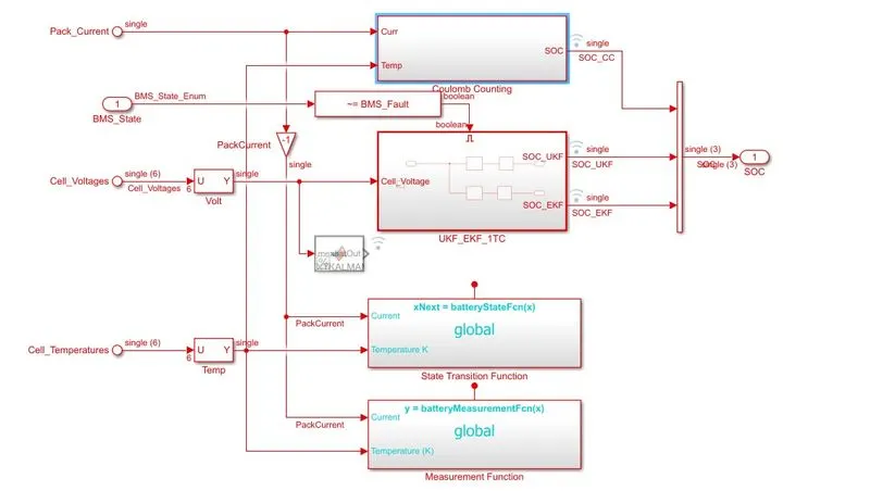
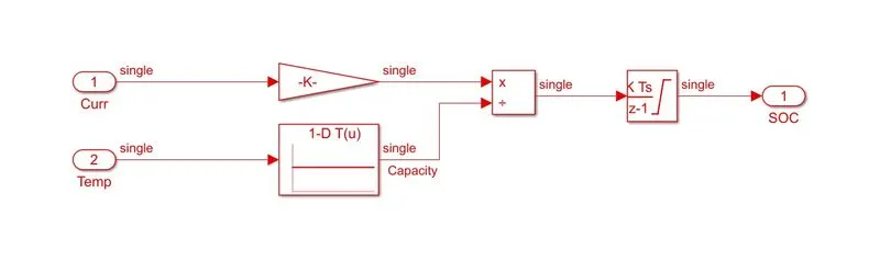
- In the coloumb counting sub system current signal and temperature signal ports are connected to gain block and look up table .
- Current signal port is connected to the gain block and temperature signal port is connected to the Look up table.
- After that signals are multiplied and divide inthe product block .
- From the product block the output is send to the discrete time integrator for estimating the SOC.
Final Conclusion -
- The 3 test cases from harness dashboard has been Simulated and the detailed report from the result have been made.
- BMS implementation on coulomb counting for SOC estimation has been discussed.
Below link are provided for the Battrey Management System -