Project 1 (Mini Project on Vehicle Direction Detection
AIM - To Develop a Simulink Model on Vehicle Direction Detection .
OBJECTIVE -
- To Develop a MATLAB Simulink model as per requirement.
- To Tag the requirements to the simulink model.
- To Create Data Dictionary & generate code of a model .
- For code generation choose , Storage class for Input signals: ImportedExtern; Storage class for Output signal: Export to File; Storage class for local signals: localizable; Storage class for calibration signals: Const.
- To Choose sample time for all signals as 0.01s.
THEORY -
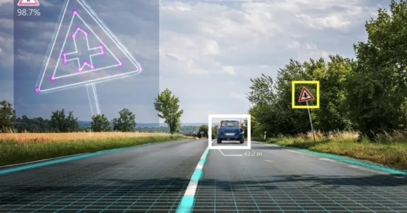
- Identifying the direction of the vehicle is one of the important & diverse features in Autonomous driving & Advanced Driver Assistance Features.
- This particular sub-feature of identifying the direction of vehicle is basically identifying the direction the vehicle is taking based on the camera input.
- Camera reads the road signs & stores into its memory with unique values for left turn, right turn & straight drive.
- Depending on the direction it is taking, final indication is given to the driver – as an indication if he is driving in the recommended direction or not.
- Vehicle Direction Determination can also be coupled along - side features like GPS systems to identify whether the vehicle is reaching its destination in an optimized manner.
- This sub feature can also be used along with Lane Detection, Highway Warning, Ramp Entry / Exit in Wrong Way Detection etc.
REQUIREMENTS OF THE PROJECT -
Requirement - 1 -:
- Steering wheel input as yaw rate (Signal name: SteeringWheel_YawDegreeInput) is the input for this system.
- This is compared against 3 angular values, one each for left turn, right turn & straight drive (Calibration Values: Right_Turn_AngularLimit, Left_Turn_AngularLimit, Straight_Drive_Steering_Angle) to say which specific direction the steering wheel is turning towards.
- Use switch blocks to compare & develop this requirement. Keep this requirement in a subsystem & output of this requirement is a local signal (Signal Name: Vehicle_Turn_Status).
Requirement - 2 -:
- Keep this requirement as a separate subsystem. Inputs to this requirement are local signal from requirement 1 (Signal Name: Vehicle_Turn_Status) & an input signal from camera (Signal Name: CameraInput_RoadSign), which confirms the occurrence of a road sign.
- Signal Vehicle_Turn_Status is compared against calibration values (Calibration Values: RightTurn_RoadSign, LeftTurn_RoadSign, Straight_RoadSign), if each of them is found equal, then each of the three corresponding output is compared against the camera input signal,
- Using a logical operator block, only one among them is finally given as output signal (Signal Name: Vehicle_Direction_Indicator).
Main Model -
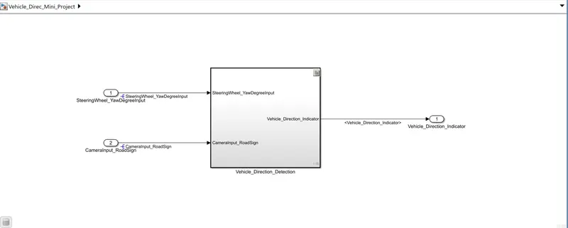
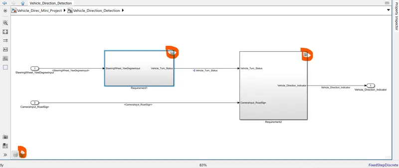
- Vehicle_Direction_Detection is the main Subsystem Model .
- In this I have use 2 input signals naming SteeringWheel_YawDegreeInput and CameraInput_RoadSign.
- I have Resolve both of the signal as these are input signals so that these signals take the value from SLDD.
- Vehicle_Direction_Indicator is the output of the system.
- I have used Display Block for indicating the Vehicle Direction .
Vehicle_Detection_Subsystem -
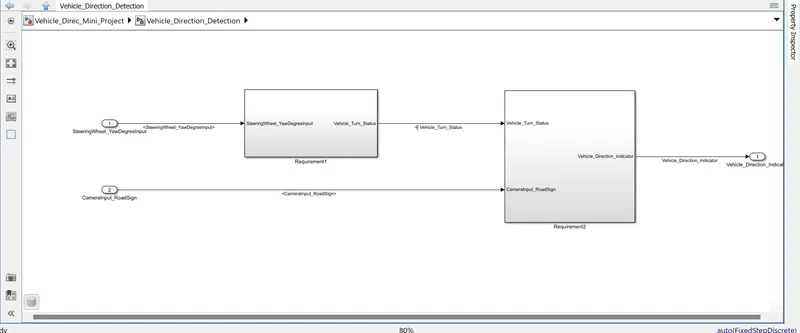
Reqiurement-1 - : Subsystem
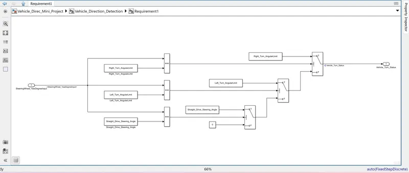
- Steering wheel input as yaw rate (Signal name: SteeringWheel_YawDegreeInput) is the input for this system.
- This is compared against 3 angular values, one each for left turn, right turn & straight drive (Calibration Values: Right_Turn_AngularLimit, Left_Turn_AngularLimit, Straight_Drive_Steering_Angle) to say which specific direction the steering wheel is turning towards.
- I have use switch blocks to compare & develop this requirement.
- Constant Blocks which is calibrated as Right_Turn_AngularLimit,Left_Turn_AngularLimit, and Straight_Drive_Steering_Angle is compared by "==" (Relational Operator Block) .
- After comparing SteeringWheel_YawDegreeInput with the different angular limit block through logical operator block , the signal is passed to the Switch block .
- In the Switch Block if the SteeringWheel_YawDegreeInput meets the requirement with Right_Turn_AngularLimit,Left_Turn_AngularLimit and Straight_Drive_Steering_Angle the signal is passed and we get the Vehicle_Turn_Status as Output.
Requirement - 2-: Subsystem
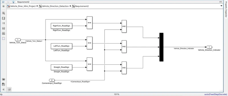
- The Output of the Requirement 1 (i.e. Vehicle_Turn_Status is the input of this Subsystem).
- CameraInput_RoadSign is the second Input .
- Here also I have used Constant block Calibrated as RightTurn_RoadSign,LeftTurn_RoadSign and Straight_RoadSign.
- Signal Vehicle_Turn_Status is compared (Used '==' Relational Operator) against calibration values (Calibration Values: RightTurn_RoadSign, LeftTurn_RoadSign, Straight_RoadSign), if each of them is found equal, then each of the three corresponding output is compared against the camera input signal.
- Using a Logical Operator block(used 'AND'), only one among them is finally given as output signal (Signal Name: Vehicle_Direction_Indicator).
Given Data For Creating Simulink Data Dictionary (SLDD) -
Signals & Calibration Data List:
|
Signal / Calibration Name |
Signal Type |
Data Type |
Dimension |
Min |
Max |
Initial Value |
Units |
|
SteeringWheel_YawDegreeInput |
Input |
Int16 |
1 |
-180 |
180 |
- |
Deg |
|
CameraInput_RoadSign |
Input |
Boolean |
1 |
0 |
1 |
- |
- |
|
Vehicle_Turn_Status |
Local |
Int16 |
1 |
-180 |
180 |
- |
Deg |
|
Right_Turn_AngularLimit |
Calibration |
Int16 |
[1 1] |
-180 |
180 |
30 |
Deg |
|
Left_Turn_AngularLimit |
Calibration |
Int16 |
[1 1] |
-180 |
180 |
-120 |
Deg |
|
Straight_Drive_Steering_Angle |
Calibration |
Int16 |
[1 1] |
-180 |
180 |
0 |
Deg |
|
RightTurn_RoadSign |
Calibration |
Int16 |
[1 1] |
-180 |
180 |
30 |
|
|
LeftTurn_RoadSign |
Calibration |
Int16 |
[1 1] |
-180 |
180 |
-120 |
|
|
Straight_RoadSign |
Calibration |
Int16 |
[1 1] |
-180 |
180 |
0 |
|
|
Vehicle_Direction_Indicator |
Output |
Boolean |
1 |
0 |
1 |
- |
- |
Data Dictionary Creation -
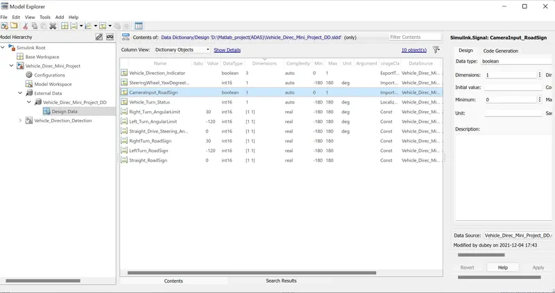
Inserting the Signal Value and Parameter Calibrated Value i the Data Dictionary as shown -
Model Advisor Check Report According To MAB Guidelines -
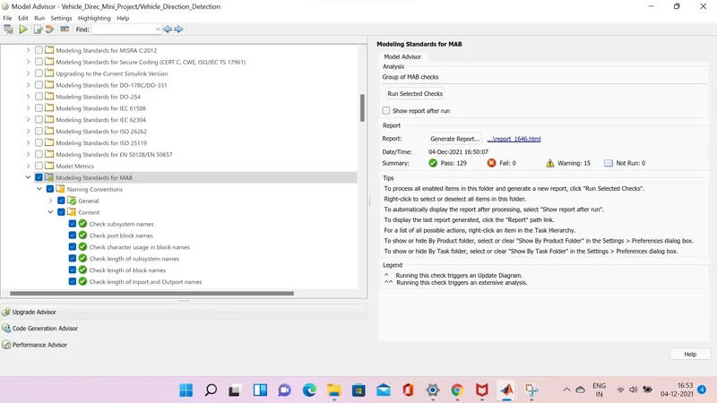
After applying the Advisor Check we get the above result as shown -
TESTING OF THE MODEL -
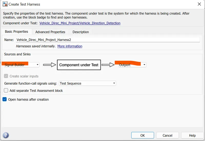
1). Model in Loop Testing (MIL) -
For Creating the MIL Environment Right click on the Vehicle_Directioin_Detection Block we get -
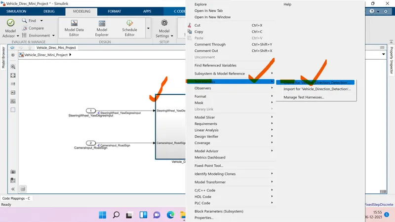
We get -
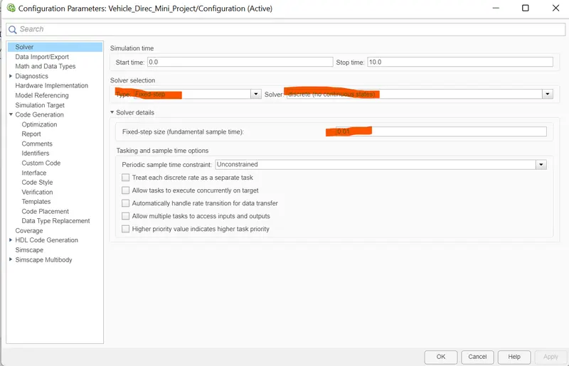
Model Configuration Setting will we as shown below -
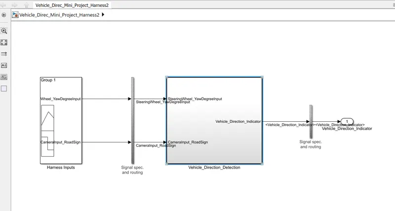
We Obtained the MIL Harness Model as -
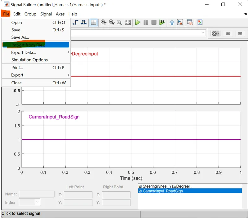
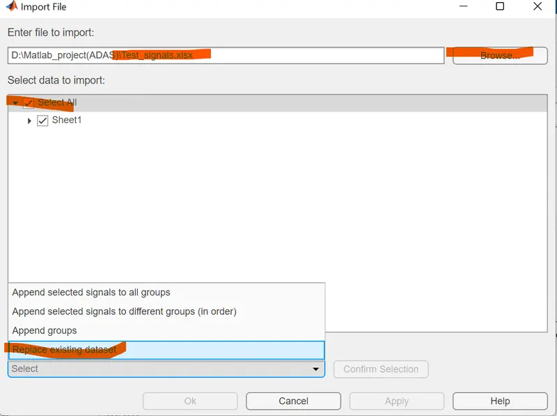
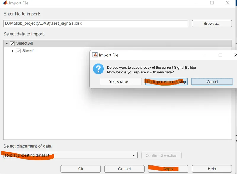
Procedure for Importing Data From Excel Sheet into the Signal Builder Block is shown Below-
2) . Software In Loop Testing (SIL) -
Steps -
1) First select the Vehicle_Direction_Detection Block and than go to the Model Setting .
2) Under the model Setting Change the paramaters as shown -
3). Under Code Generation Change the Target File as ert.tlc and its Description as Embedded Coder as shown -
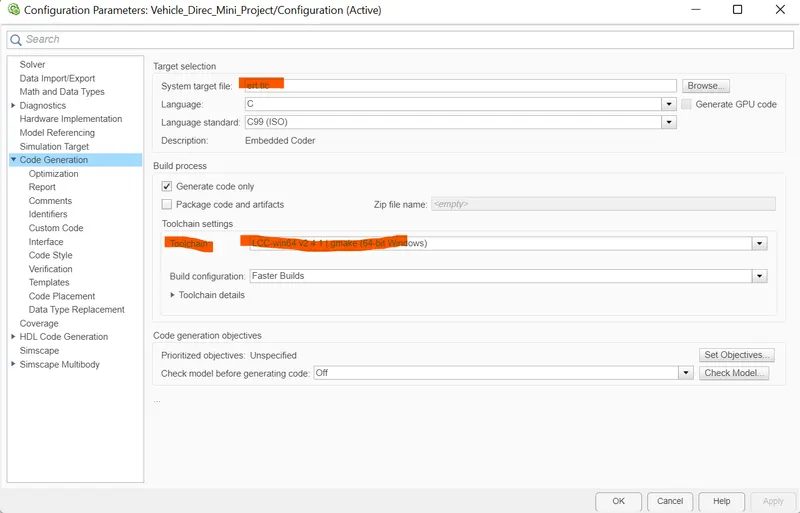
4).Now select the main model Vehicle_Direction_Detection Block Right Click on it follow the procedure as shown -
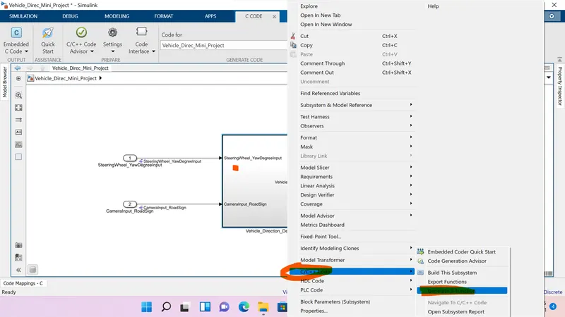
5). Generate the S - Function on clicking in the Generate S-Function.
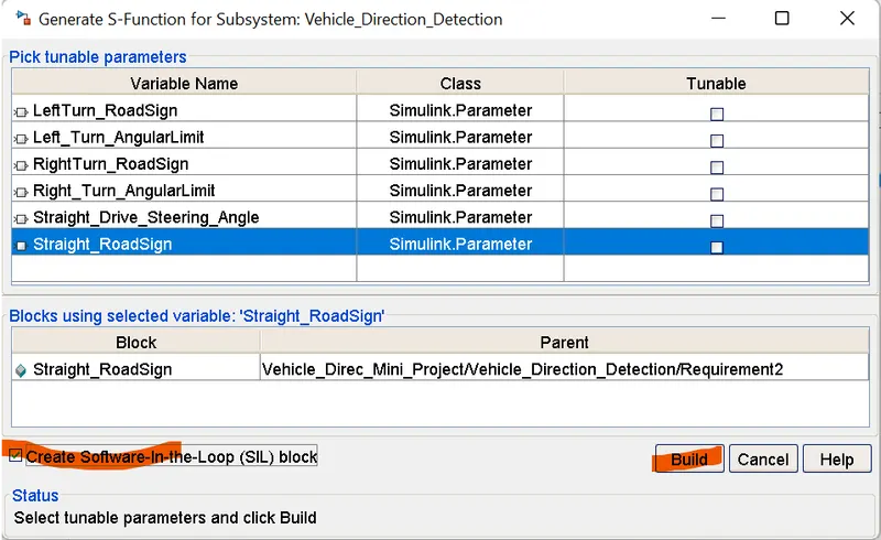
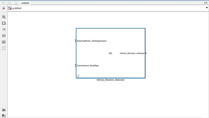
6)After Clicking on the Build we get the Generated SIL Block as shown in a separate 'untitled file'.
7) For Harnessing we have to right click on the SIL Block and follow the procedure -
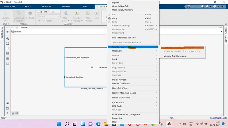
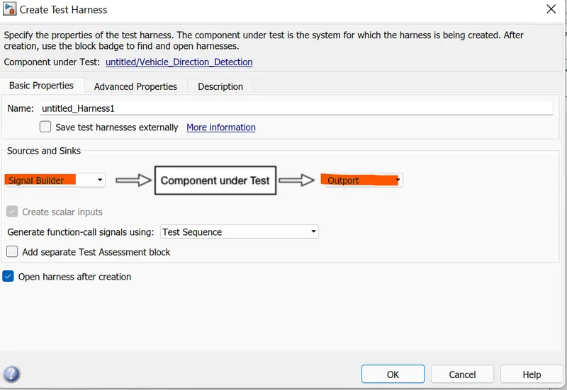
Finally we get the Generated Test Harness Model .
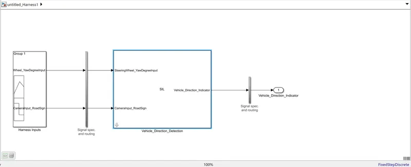
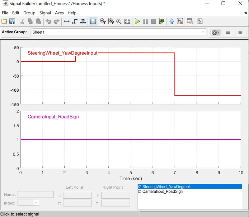
Now , we have Two Harness Input in the form of Signal Builder Block as
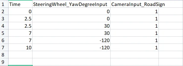
- Wheel_YawDegreeInput - From the excel sheet we import the data to the signal builder block.
- For CameraInput_RoadSign our input will we always '1' in signal builder .
Excel Sheet -
Importing The Data from Excel to the Signal Builder Block .
Finally we get -
Requirement And Tagging -
Steps -
1). First Copy the requirement from the questions and pasteit into the Word file and save it in the same folder where our Simulink Model has been saved .
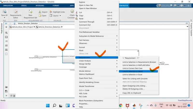
2). For tagging the Requirement 1 Subsystem ,highlight the Requirement 1 eading in the word file and than select the requirement 1 subsystem , right click on it , goto requirement ,select the option 'Link To Selecton In Word' . In this way requirement 1 subsystem will be tagged.
3). Same procedure will we followed for the Requirement 2 Subsystem Tagging and also for Simulink Data Dictionary Tagging .
4). After tagging model will look like as shown -
CONCLUSION-
1).As per the requirement MATLAB Simulink Model have been developed.
2).Data Dictionary also been created .
3). Code Generation also has been done .
4). Advisor Check also has been Done .
5). MIL and SIL Testing also has been done.
6). Requirement Tagging also has been done.