Final Project: Design of an Electric Vehicle
Create a MATLAB model of electric car which uses a battery and a DC motor. Choose suitable blocks from the Powertrain block set. Prepare a report about your model including following:
Objectives:
- System level configuration & Model parameters
- Results
- Conclusion
System level configuration & Model parameters:
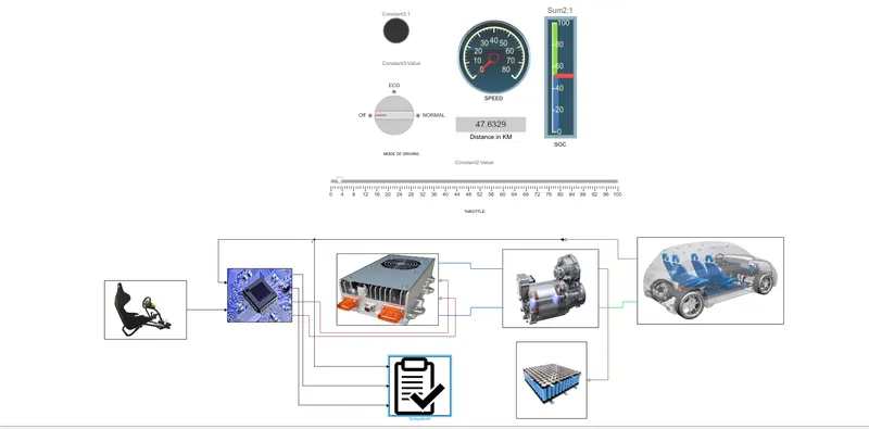
The high level model of the electric vehicle is shown, the user input is given to the model mashed on the command the speed, SOC, distance and mode indication can be identified using the dash board and the detailed explanation for the each subsystem is done below.
DRIVE CYCLE SUBSYSTEM:
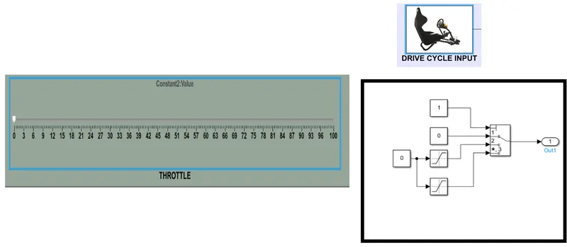
The throttle from the manual variation is given to the drive cycle subsystem and the value is given to the controller depending on the mode of operation this is achieved by the saturation block. Each mode determines the speed limit of the vehicle.
The output from the drive cycle is given to the controller block.
CONTROLLER SUBSYSTEM:
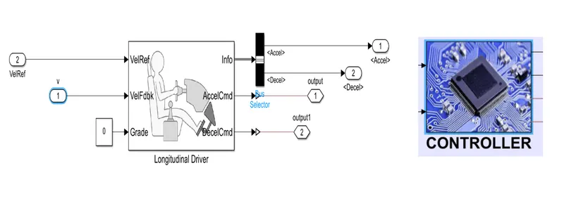
Using the longitudinal driver block the acceleration command and declaration is separated and given as the input to the controller accordingly. Also the longitudinal driver takes the feedback and corrects the mistakes accordingly.
The longitudinal driver sends the output to the motor controller block subsystem and output result analysis block.
MOTOR CONTROLLER SUBSYSTEM:
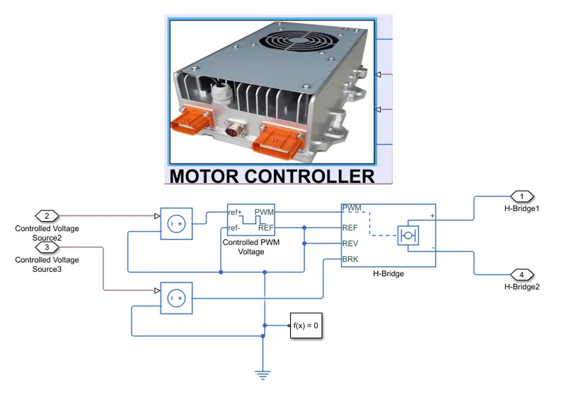
The motor controller block has the controlled PWM signal that generates the PWM based on the acceleration and declaration. That is given to the H-bridge that takes care of the forward and reverse motion of the vehicle. The other purpose is to get the external power from the battery based on the signal given to it and give it to the motor.
MOTOR SUBSYSTEM:
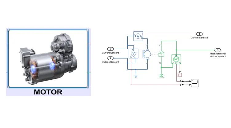
The DC motor is used for the traction purpose and that is controlled by the PWm generator and H-bridge.
The motor is coupled with the vehicle body and the speed sensor. Also the vehicle body has a separate subsystem.
VEHICLE BODY SUBSYSTEM:
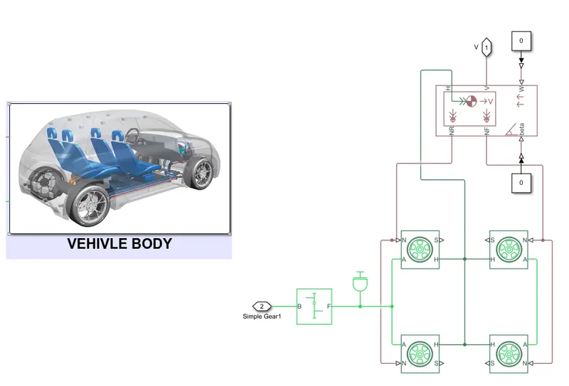
The vehicle body has the inertia and gear transmission connected with the tyre and vehicle body.
Forces like wind and gradeability are kept as zero for the calculation. Also the tyre is used with the magic formula for the calculation of pressure.
BATTERY SUBSYSTEM:
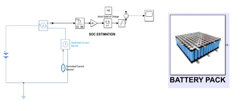
The 10 kWH battery pack is used for the calculation and the coulomb counting method is used for the calculation for the SOC. In this calculation the initial value for the battery SOC is kept as the 100% .
And the value of the battery is given to the scope for better understanding.
RESULTS:
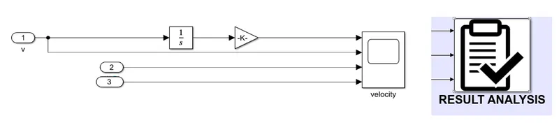
In the result analysis subsystem the distance travelled , speed , acceleration and deceleration is shown.
CONCLUSION:
Thus the electric car is designed amd simulated the results are shown.
model file link:
https://drive.google.com/drive/folders/1vi-tsVdcugWfk3joskotNacyjY-ffWcX?usp=sharing