Analysis of ATV(All-Terrain Vehicle) simulation
Carry out a system-level simulation of an all-terrain vehicle.
Download the model from the given link:
https://www.mathworks.com/matlabcentral/fileexchange/70576-baja-all-terrain-vehicle-atv-model
Prepare a technical report explaining the model properties & comments on the results.
The diagrammatic example of ATV is given below:
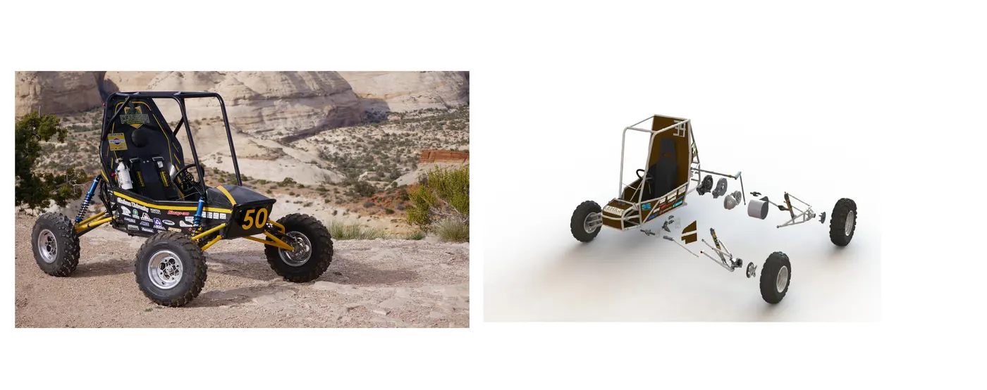
There are two types of system-level simulation of an all-terrain vehicle.
For both models, the concept is the same, and 90% of the components are the same for both models.
MODEL 1
AIM:
To run the system-level simulation of an all-terrain vehicle.
SIMULINK MODEL:
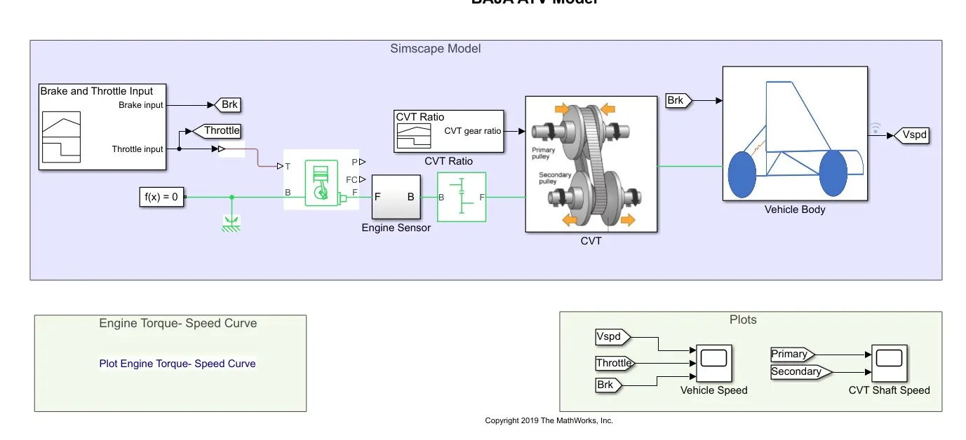
DESCRIPTION:
This model shows the simulation of an ATV vehicle with the input as constant from the signal builder and the output of velocity and brake of the ATV vehicle with the rpm speed of the shaft.
With the signal building, the signal for brake input and throttle for the engine is given to the generic engine. The generic engine block takes the input of the throttle and rotation of the shaft accordingly. The shaft from the generic engine block is connected to the engine sensor which indicates the speed of the shaft, and parallelly the shaft is connected to the simple gear. The simple gear reduces the speed of the shaft to a certain level and is connected to the CVT subsystem.
The CVT subsystem is used to change the speed with the help of a pulley, which is done by a variable gear ratio block and this gets the input from the CVT gear ratio signal builder. And finally, the shaft is connected to the vehicle body subsystem which consists of a double-shoe brake and tires, vehicle body block. This subsystem gets the brake input, which is connected to the double-shoe brake with the input the double-shoe brake, stops the tires and all details are given to the vehicle body block. The vehicle body block calculates the velocity of the vehicle and shows it in the scope.
The Simulink blocks used in the model are
- Signal builder
- Generic engine
- Simple gear
- Ideal rotational motion sensor
- Scope
- Mechanical rotational reference
- Variable gear ratio
- Inertia
- Vehicle body
- Tire
- Double - shoe brake
SIGNAL BUILDER:
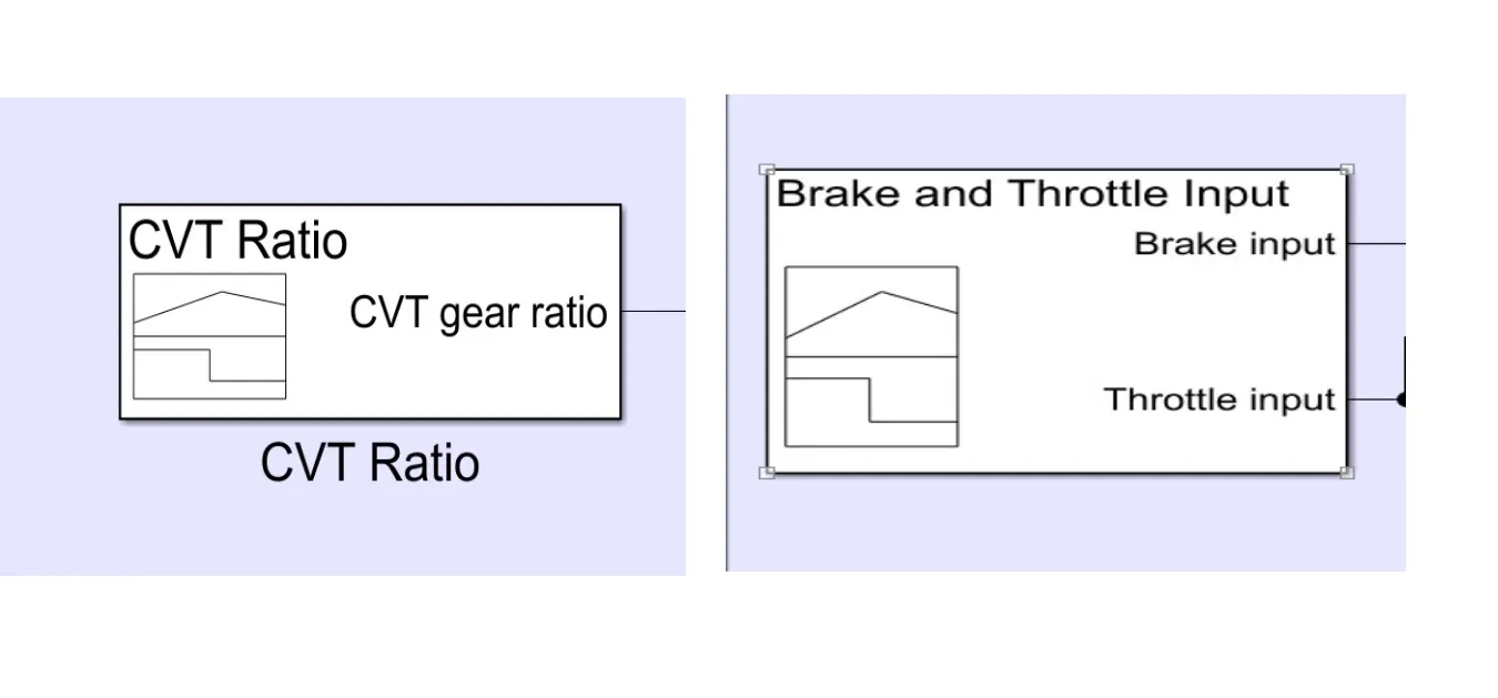
- The signal builder builds the input signal, needed for the condition for the brake input, throttle input, and CVT gear ratio.
- The signal builder gives the signal to the ATV vehicle.
- Using the signal builder our own signal was created for the period of the 80s.
- By using the signal building the signal for brake input and throttle for the engine is given to the generic engine, which determines the engine performance.
- The CVT gear ratio builds the signal for the variable gear ratio block which determines the vehicle speed.
GENERIC ENGINE:
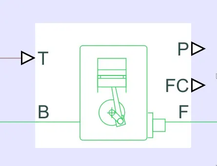
- The generic engine gets the input from the throttle signal and works accordingly (T).
- The engine case (B) is connected to the mechanical reference block.
- The crankshaft rotates (F) based on the input of the throttle (fuel signal) and connected to the sensor.
- The generic engine is operated with predefined values of torque, speed, inertia, etc.
IDEAL ROTATIONAL MOTION SENSOR: From engine sensor subsystem, CVT subsystem
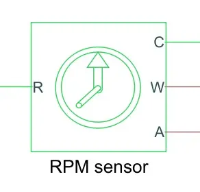
- This sensor measures the rotation movement of the engine shaft.
- This sensor gives the output of velocity (W) and angular displacement(A).
- The velocity is taken as the rpm of the engine and displayed in the scope.
- Also used to find the rpm of the primary and secondary shaft.
MECHANICAL ROTATIONAL REFERENCE:
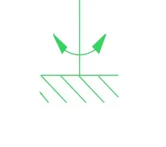
- The mechanical rotational reference can also be connected anywhere in the mechanical circuit, it is mandatory to connect the mechanical rotational reference when rotational-related components are used.
- Also used with an ideal rotational motion sensor.
SIMPLE GEAR:
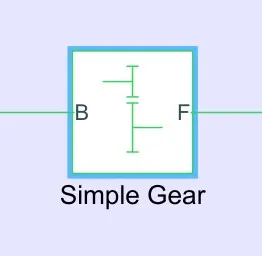
- It is the fixed-ratio gearbox, it changes the speed to a certain level.
- This block can also change the direction of the speed.
CVT SUBSYSTEM
- Likewise the simple gear the CVT subsystem is used to change the speed of the shaft
- The advantage here is we can change the speed in the wide range.
Working of variable speed adjustment in CVT
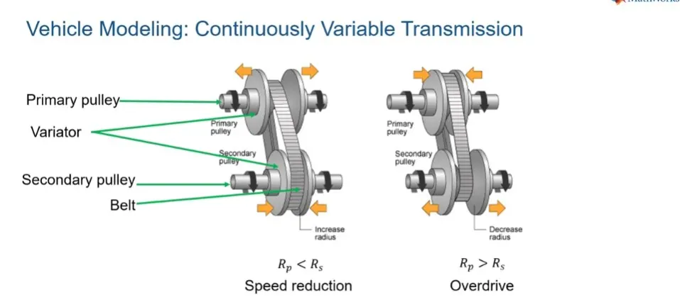
Here the primary pulley is variable and the secondary pulley is fixed. when the primary pulley is moved away it reduces the speed in the secondary shaft. when the primary pulley is moved inside it increases the speed in the secondary shaft.
Variable ratio gear:
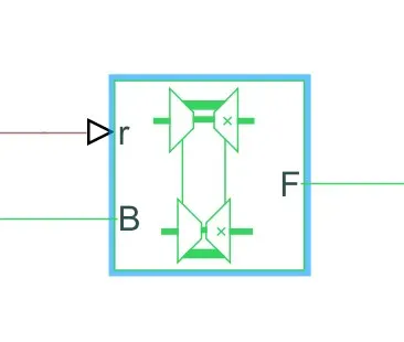
- The variable-ratio gear block uses the CVT transmission.
- The block gets the input from the gear ratio signal builder and makes the follower runs according to base
The speed changes of the base and follower are measured using the ideal rotational sensor and the values are shown in the scope
And finally, the shaft is connected to the vehicle body subsystem.
INERTIA:
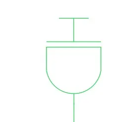
- The inertia block is used to attach to the shaft, to provide the mechanical rotational inertia.
- This inertia makes the slow variation of the speed in the shaft.
VEHICLE BODY SUBSYSTEM
The vehicle body block consists of a vehicle body block, tire, Double - shoe brake
VEHICLE BODY BLOCK
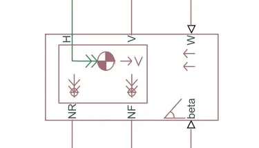
- Using this block we can specify the vehicle mass, the number of axles per wheel, the distance of the axle from the center, the height of the vehicle, wind velocity, the inclination of the vehicle, etc.
- The constant values are given to the parameters
- Port(H) is connected to the mechanical translation part, Port(v) gives the velocity of the vehicle, Port(W) connected to the wind constant, Port(beta) is connected to the inclination of the vehicle, Port(NF) is connected to the front tires and Port(NR) is connected to the rear tires
DOUBLE-SHOE BRAKE:
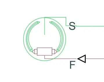
The break input from the signal builder is connected to the double-shoe brake with the gain of 1000.
The double-shoe brake's other end is connected to the rotating shaft, when the input value is increased the brake reduces the speed of the shaft.
TIRE:
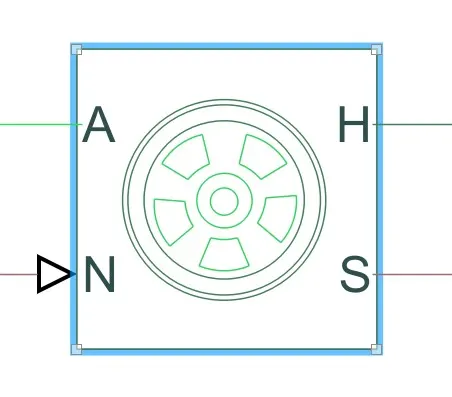
- This block represents the tire in the vehicle.
- We can specify the inertia, stiffeners, damping, etc
- Port(N) is connected to the physical signal input, Port(S) is gives the physical output, Port(H) is connected to the mechanical translational, Port(A) is connected to the mechanical rotational
- The magic formula represents the B-stiffness, C-shape, D-peak, E-curvature of the tire.
SCOPE
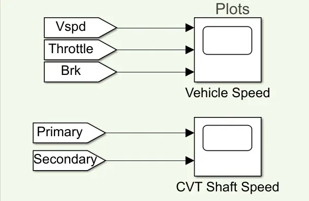
- This scope shows the input and output of the ATV vehicle.
- The first port shows the graph of the velocity.
- The second port shows the graph of the throttle input for the engine.
- The third port shows the graph of the brake input for the vehicle.
- The fourth and fifth port gives the rpm of primary and secondary shafts.
- Through this scope, we can analyze the signal for the particular input, also for a particular time.
By using these all the bock the required system is created in Simulink platform
RESULT:
The scope results are shown below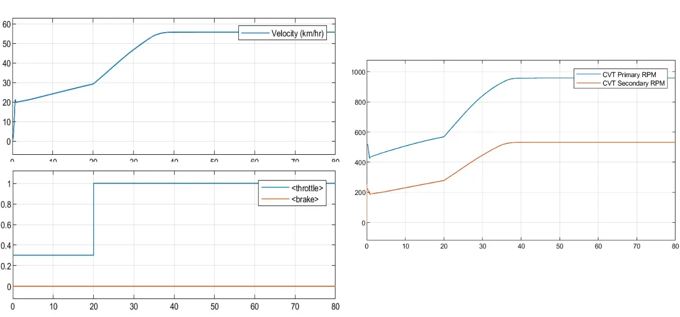
After performing various calculations the Simulink model is submitted to give the accurate result.
Thus a technical report explaining the model properties & simulation results is given.
*************************************************************************************************************
MODEL 2:
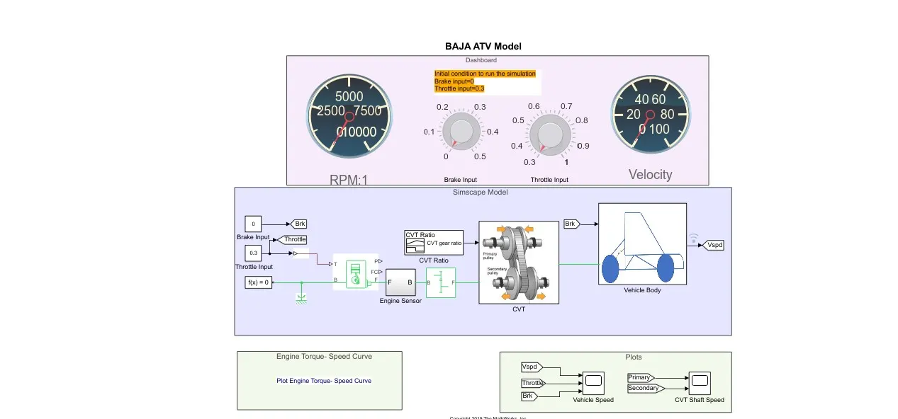
THE ONLY DIFFERENCE IN THE MODEL 2:
We can change the input parameters in model 2 by using dashboard blocks but in the case of model 1, it is the constant input from the signal builder.
We can visually understand the change in value for the output to the input in model 2 using dashboard blocks but in the case of model 1, it is the output that is only seen in the scope.
OTHER THAN THESE DIFFERENCES THE BOTH THE MODEL 1 AND THE MODEL 2 ARE SAME IN FUNCTION AND BLOCKS USED.