DC Motor Control
OBJECTIVE-1:
To modify the model ‘Speed control of a DC motor using BJT H-bridge’ such that armature current doesn’t shoot up when the motor changes direction from forward to reverse.
The armature starting current of the DC motor can be changed by 4 methods
- PWM
- Armature control
- Field control
- Starter rheostat
MODEL DESCRIPTION:
The BJT when used for power switching applications, operates as an IGBT. When it is conducting, a forward voltage Vf is developed between collector and emitter. Therefore, the IGBT block can be used to model the BJT device.
The IGBT block does not simulate the gate current controlling the BJT or IGBT. The switch is controlled by a Simulink® signal. The DC motor has 5 HP 24V 1750 rpm. It simulates a fan type load. The armature mean voltage can be varied from 0 to 240 V when the duty cycle is varied from 0 to 100%.
The H-bridge consists of four BJT/Diode pairs (BJT simulated by IGBT models). Two transistors are switched simultaneously: Q1 and Q4 or Q2 and Q3. When Q1 and Q4 are fired, a positive voltage is applied to the motor and diodes D2-D3 operate as free-wheeling diodes when Q1 and Q4 are switched off. When Q2 and Q3 are fired, a negative voltage is applied to the motor and diodes D1-D4 operate as free-wheeling diodes when Q2 and Q3 are switched off.
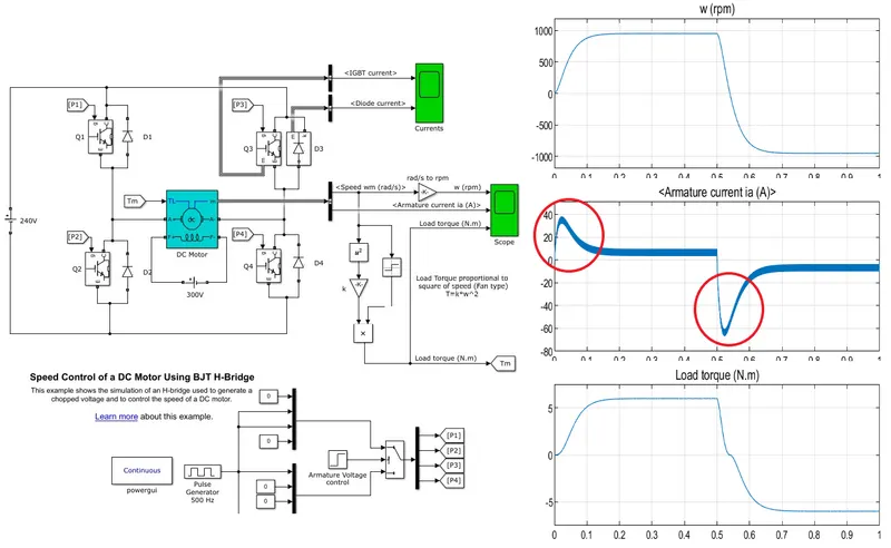
In the above model Speed control of a DC motor using BJT H-bridge the armature starting current is very large then it gradually reduces. In order to control the large starting current the PWM technique is more effective ,so the value of the PWM signal is reduced from 75% to 45% this means that the voltage value given to the motor is reduced. so after changing the value the starting current and negative reverse current does not shoot up. In order to minimize the current deviation ,the PWM frequency of 500hz can be increased so the deviation is reduced.
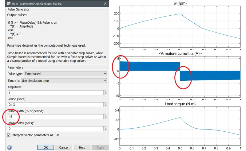
RESULT:
Thus by adjusting the PWM signal the value of starting current is controlled and reduced.
Other methods like voltage control(armature & field) thus increasing the voltage from 0 to maximum the starting current can be controlled or by using the 3 point , 4 point starter the value of the starting current can be reduced.
------------------------------------------------------------------------------------------------------------------------------------------------------------------------------------------------------------------------------
OBJECTIVE-2:
To compare the ‘The Four-Quadrant Chopper DC Drive (DC7) block’ with the H-bridge model.
H-bridge:
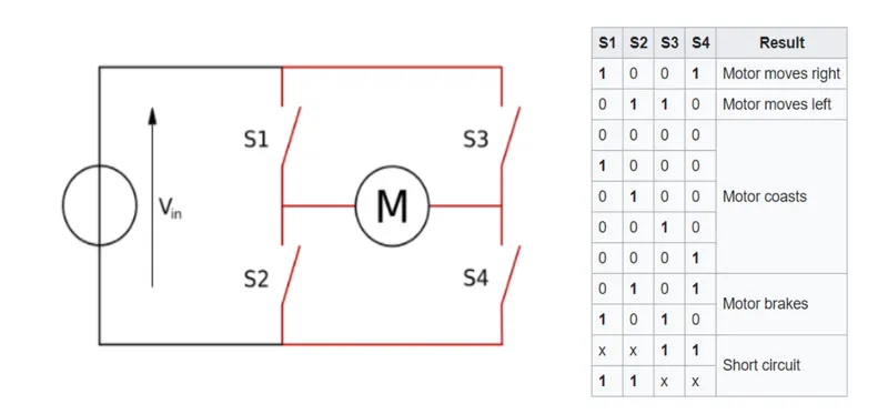
The H-bridge is used for the operation of forward and reverse operation of the motor.the H-bridge has several operating modes such as motor moves right ,moves left ,coasting , barking, short circuiting.
Operating mode:
4 quadrant chopper:
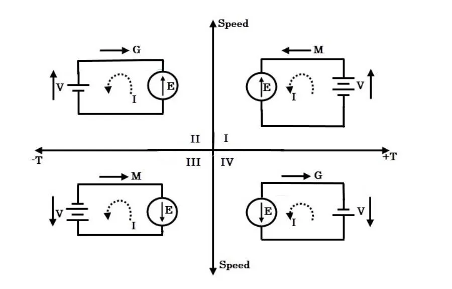
The new propose chopper has features to overcome the drawbacks of conventional H Bridge Chopper. This chopper has seven modes of operation such as, driving,field weakening,generator,Parallel mode, regenerative braking, resistive braking and reverse mode.
Operating mode:
|
Four-Quadrant Chopper DC Drive |
H-bridge |
|
Can operate in 4 mode |
Can operate in 2 mode |
|
Applications: Electric traction system Battery operated vehicle Lift and crane Position control system |
Applications: Inverter circuits Robotics Motor controllers |
|
Regenerative braking is possible |
Regenerative braking is not possible dynamic braking is possible |
|
It has wider range of torque and power |
Comparatively narrow range of torque and power |
|
Speed and current controllers are available |
Speed and current controllers are unavailable |
|
Highly efficient |
Low efficient compared to 4 quadrant chopper |
-----------------------------------------------------------------------------------------------------------------------------------------------------------------------------------------------------------------------------
OBJECTIVE-3:
To Make a suitable EV model using a DC7 block and make a result report.
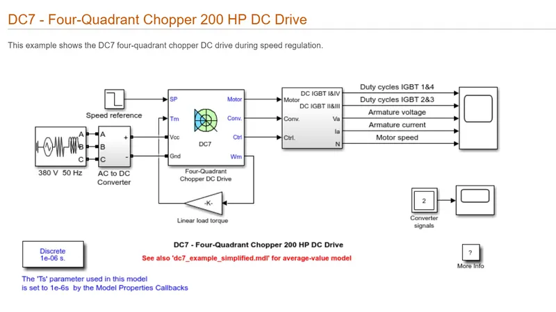
The example of DC7 block is available in matlab help ,let me take this example for further studies.
DESCRIPTION:
The 200 HP DC motor is separately excited with a constant 150 V DC field voltage source. The armature voltage is provided by an IGBT converter controlled by two PI regulators. The converter is fed by a 515 V DC bus obtained by rectification of a 380 V AC 50 Hz voltage source. In order to limit the DC bus voltage during dynamic braking mode, a braking chopper has been added between the diode rectifier and the DC7 block.
The first regulator is a speed regulator, followed by a current regulator. The speed regulator outputs the armature current reference used by the current controller in order to obtain the electromagnetic torque needed to reach the desired speed. The speed reference change rate follows acceleration and deceleration ramps in order to avoid sudden reference changes that could cause armature overcurrent and destabilize the system. The current regulator controls the armature current by computing the appropriate duty ratios of the 5 kHz pulses of the four IGBT devices. For proper system behaviour, the instantaneous pulse values of IGBT devices 1 and 4 are opposite to those of IGBT devices 2 and 3. This generates the average armature voltage needed to obtain the desired armature current. In order to limit the amplitude of the current oscillations, a smoothing inductance is placed in series with the armature circuit.
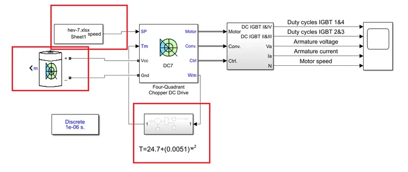
This is the general description of the model given by the Matlab in order to change the model for EV application ,let's change the duty cycle of the model ,battery,torque equation
The battery of 515V with the 100Ah, the duty cycle of my own driving cycle for the 15s and the linear torque equation is changed with the challenge6 torque equation.
The torque equation used hear is T=24.7+(0.0051)w2
Result:
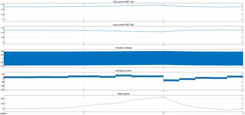
From the graph ,for the duty cycle of15s . I can conclude that the motor traces the exact path of the duty cycle.The armature current fluctuates but even follows the path of the reference signal.