Design of backdoor
BACKDOOR DESIGN
Objective:
Use the provided styling surface to come up with a back door design, use appropriate design methodologies and provide the necessary reinforcements and embosses.
Software Used:
NX CAD
BACKDOOR INTRODUCTION-
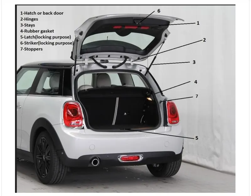
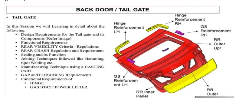
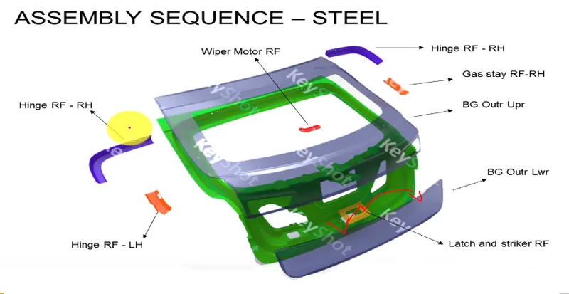
An automobile back door or Tailgate is the panel that covers the boot (or trunk) of an automobile. It enables access to the main luggage compartment. A hinge allows the boot lid to be raised, while devices such as springs or gas cylinders hold it up in the open position The Backdoor is an assembly of many parts such as inner panel, outer panel upper, outer panel lower and Reinforcement. Inner panel is attached to the outer panel using mastic sealant.
Total no. of parts in Backdoor are:
- Back door outer panel (upper)
- Back door outer panel (lower)
- Back door inner panel
- Hinge reinforcements
- Gas stay reinforcements
- Latch and striker reinforcements
- Wiper motor reinforcements
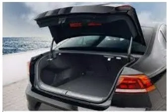
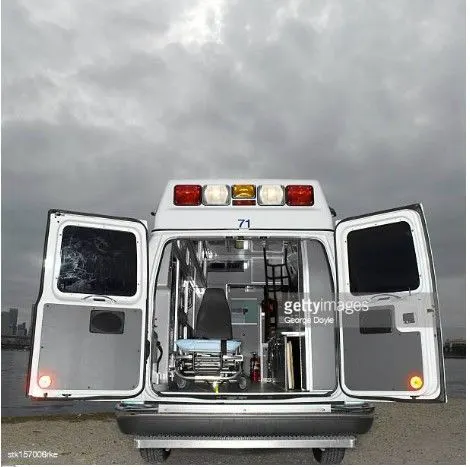
Types of doors based on working position,
- Top Mounted Door
- Side mounted Door
- Bottom Door
DESIGN CONSIDERATON FOR BACKDOOR INNER PANEL:
- Rear visibility
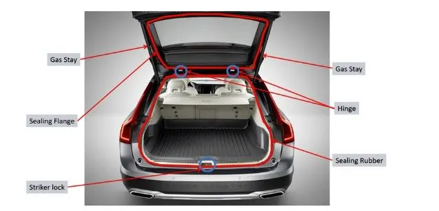
- Support structure like hinges and gas stays.
- Mounts for wiper motor, tail lamps, and other wiring loops.
- Fit and clearances.
- Boot space
- Sealing and its functions
- Joining techniques like hemming, spot welding etc.
- Load cases
- Force distribution
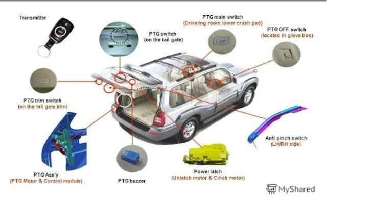
The back door is operated by two types of comodities
1.electrically operated
2.gas stay powered
the main purpose of these mechanisims is to open the back door without heavy efforts, because the backdoor have different parts and the weight of the back door is high, so we are not able to open the back door manually, so we introduced these two types comodities. and these also decides the premium of the car, mostly the electrically operated used in premium cars.
1.gas stay powered
2.electrically operated
Back Door Assembly:
- Inner panel
- outer panel
- hinge and its reinforcement
- wiper motor reinforcement
- latch & stricker and its reinforcement
- gas stay reinforcement
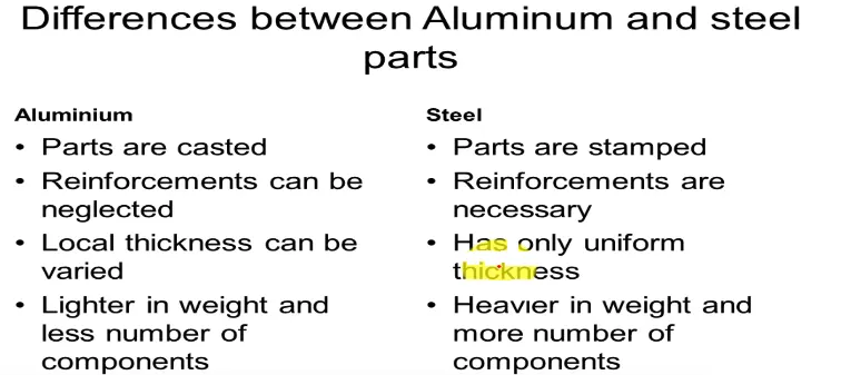
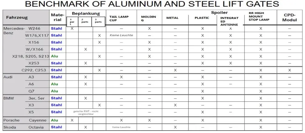
the major problem in back door is material selection. mostly in past days steel is used, but it makes a very problems the steel parts have heavy weight,so it reduces the fuel economy, insted of steel presently in high end cars aluminium is used, the main objective of aluminium it have less desnser material and its sutaible for complex shapes, and it also gives the thcikness locally because it it done cating, in case of steel we used deep drawing operation. there are some of the advatanges and disadvantages are there
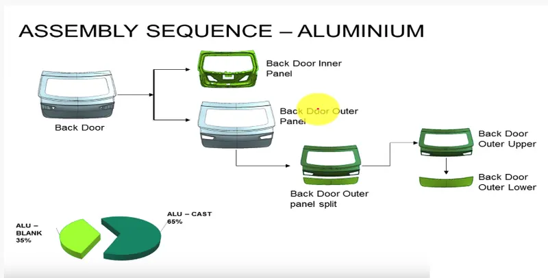
so by using of aluminium we can reduce the number of parts and assembly involvement. and it is castly material.
LOAD TEST
Various load test executed on backdoor for testing its durability, toughness so that it can with stand any type on accident.
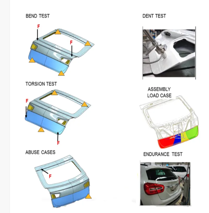
these are the certain tests are done in back door,not only back door all components must pass these tests but different components have different test because of the functionaly.
Different types of Sheetmetal operations are done in the Back Door
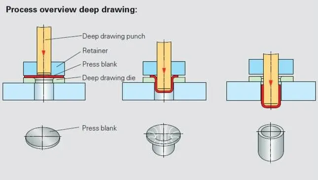
Deep Drawing:
The metal deep drawing process is an effective method of manufacturing of cups, cans and other similar deep drawing products. The deep drawings having two main categories.
- First- stage drawing: The blank shape of metal is placed on the die and contact with the punch. When the metal specimen is flat piece of sheet metal used in forming and finish the product. Initially the punch moves in downward direction. The outer rim of blank is subjected to pure radial drawing (drawing toward in vertical axes) between die and blank metal. The metal become a bend and sliding over die and also stretched between die and punch. The metal in vicinity of punch head and contact with it bend and slide over radii and stretch over punch head.
- Redrawing: The components drawn from first stage again it is redrawn convert into more depth to form a cup shape in the die and punch. The second stage of drawing is called as redrawing.
Trimming:
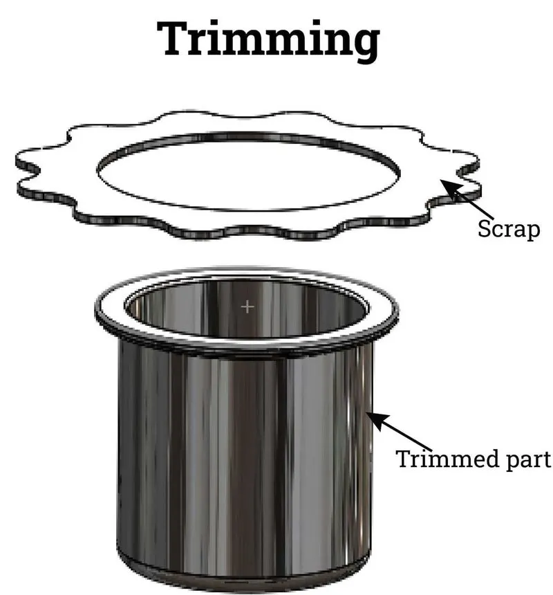
Trimming is the removal of excess metal from a stamped part to allow the part to reach the finished stage or to prepare it for subsequent operations.
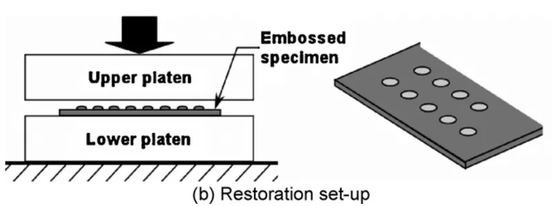
Embossing:
Embossing is a metal forming process for producing raised or sunken designs or relief in sheet materials by means of matched male and female roller dies, theoretically with no change in metal thickness or by-passing sheet or a strip of metal between rolls of the desired pattern. Metal sheet is drawn through the male and female roller dies producing a pattern or design on the metal sheet. Depending on the roller dies used, different patterns can be produced on the metal sheet.
Materials commonly used in the metal embossing process include:
- Aluminum alloys
- Steel alloys
- Zinc
- Copper
- Galvanized steel
- Brass
- Cold rolled steel
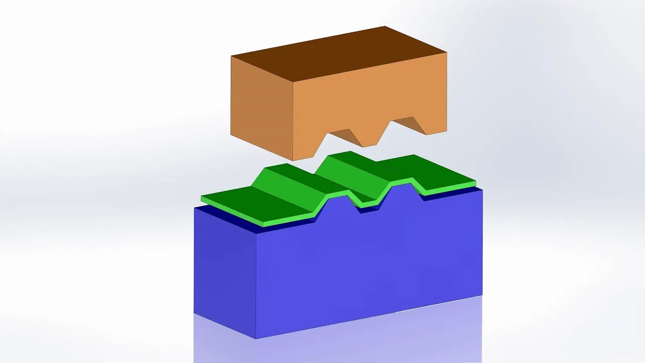
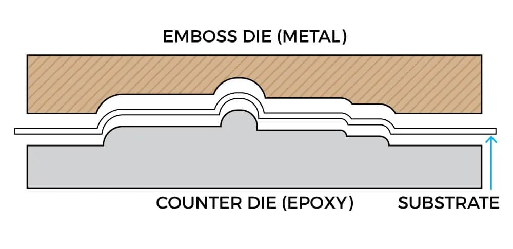
There are basically three types of metals that are used for embossing dies.
- Magnesium dies : They are used for easy embossing projects that have short runs. It also allows for special hand tooling.
- Brass dies : They are the most popular embossing dies. They are very flexible and give the embosser leeway to create fine lines, sculptured images, combo foil stamping and embossing. They are also very good for images requiring extensive hand tooling. You can make brass dies by machines or by a semi-photographic process. The photograph is transferred onto the die to use as a guide for drawing.
- Copper dies : They are used as an in between to magnesium and brass. However copper dies do not permit hand tooling.
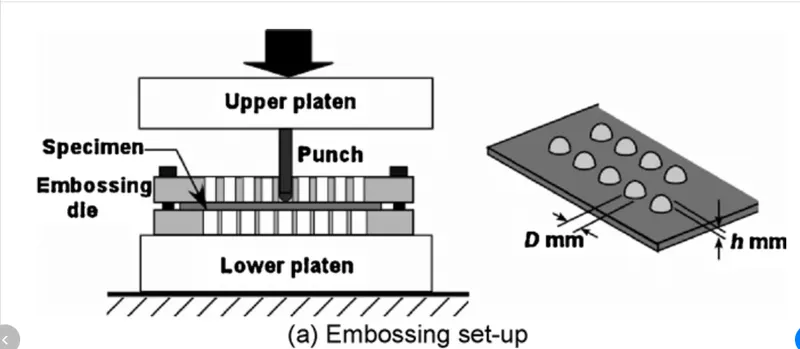
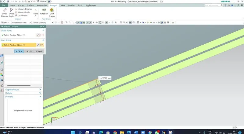
Hemming:
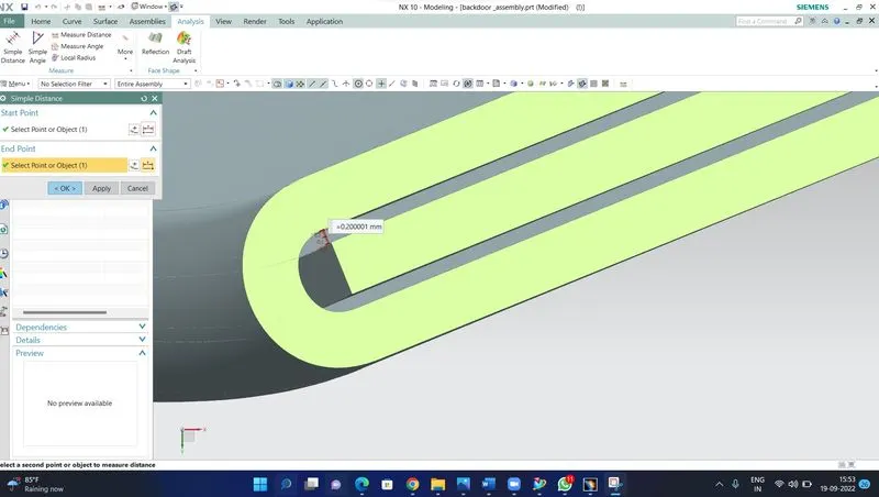
Hemming is a forming operation in which the edges of the sheet are folded or folded over another part in order to achieve a tight fit. Normally hemming operations are used to connect parts together, to improve the appearance of a part and to reinforce part edges.
In car part production, hemming is used in assembly as a secondary operation after deep drawing, trimming and flanging operations to join two sheet metal parts (outer and inner) together. Typical parts for this type of assembly are hoods, doors, trunk lids and fenders.
There are various types of hemming operations:
- Conventional die hemming: In conventional die hemming, the flange is folded over the entire length with a hemming tool.
- Roll hemming: In roll hemming, the hemming roller is guided by an industrial robot to form the flange.
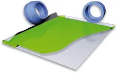
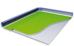
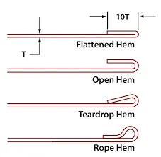
Open Hem: A Hem has a full round feature and a return flange. In open hem bend angle is equal to 180 degrees.
Tear drop Hem: In tear drop hem the bend angle is greater than 180 degrees.
Closed Hem: Hems without any inside radius are called as closed hem. Closed hems are not recommended if the hem geometry is to be painted or if the material used is SST or Aluminium.
Design Methodology:
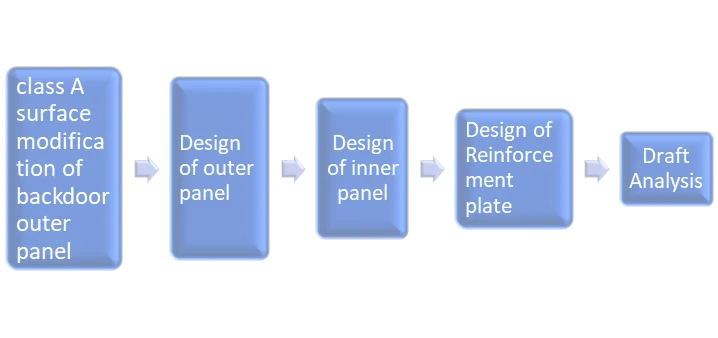
Class A surface has been provided to us, to design the backdoor. While designing I followed the top down approach in top down approach we have to create an assembly first, and then required parts in it. Top down approach is too much handy as we can easily active the part and change it according to the final assembly design required as we don’t have to worry about the position of parts the parts are easily position in proper way by the command called wave geometry linker.
Blanking:
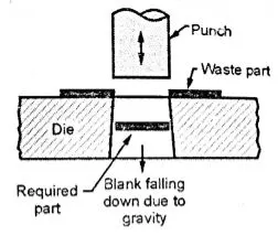
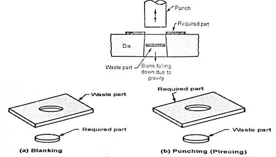
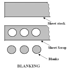
Blanking is a cutting operation of a flat metal sheet and the article punched out is known as blank. Blank is the required product of the operation and the metal left behind is considered as a waste.
Punching:
It is similar to blanking only the main difference is that, the hole is the required product and the material punched out from the hole is considered as a waste.
inputs for designing of backdoor:
- Outer Panel - 0.75 mm
- Inner Panel - 0.75 mm
- Reinforcements - 1.5 mm
skin data is given
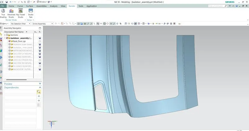
CLASS A SURFACE:
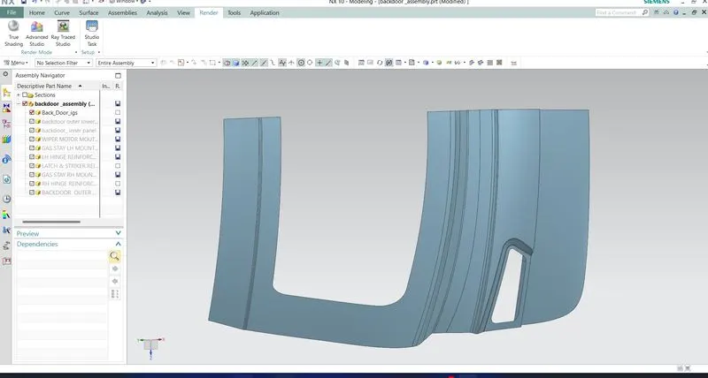
backdoor outer upper and lower class a surface has to be repaired according to the smoothness. After repairing the surfaces, the door is divided into two parts as Door Outer Upper and Doo Lower Panel.
First, we need to create the Tooling direction for the Deep drawing operation. It shows that all the operations like embossing is done by considering this vector direction and it will help in manufacturing the part,
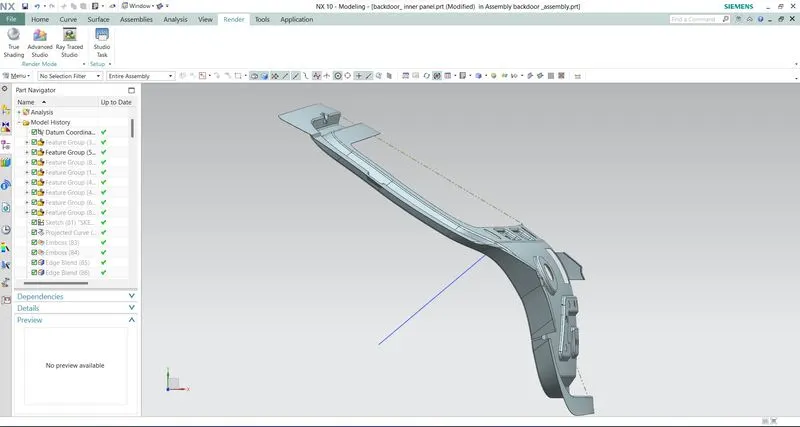
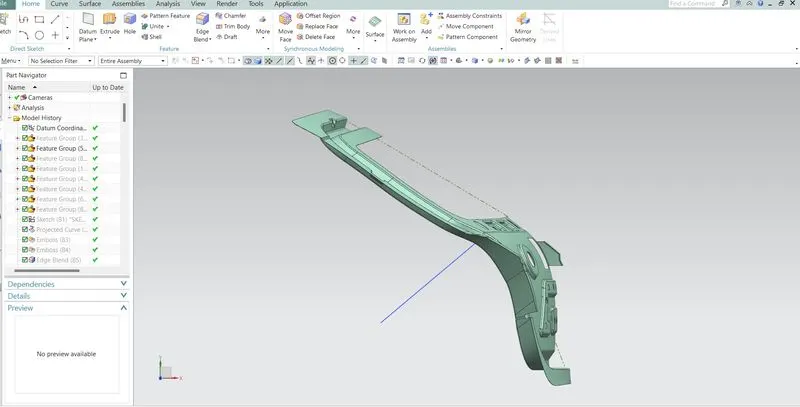
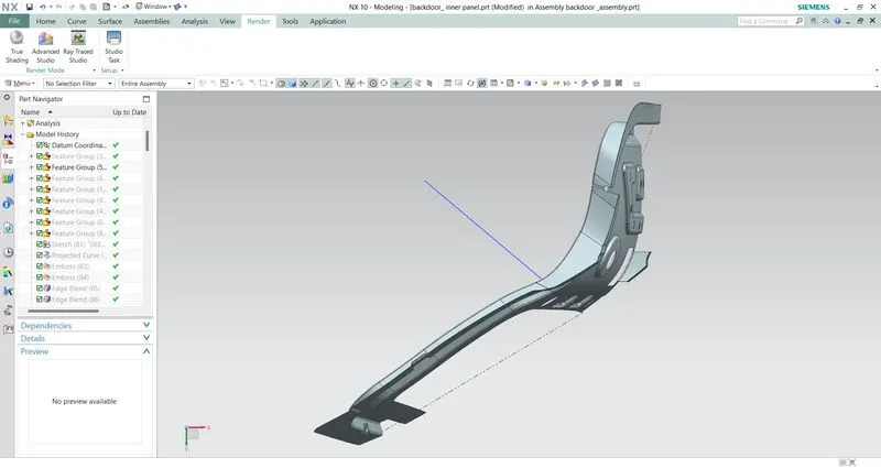
After that we have to create Sealing Flange by offsetting the outer panel to the specific distance.
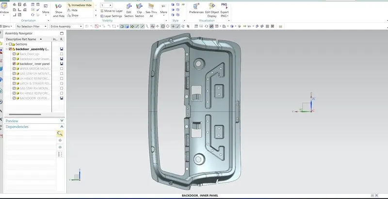
Then we will be creating the Back door inner panel flange by offsetting the outer surface at a distance considering the sheet thickness and thickening direction.
Then created the connecting flange to join the inner panel and sealing flange.
Then for the windshield panel mounting, windshield panel is created and joined with sealing flange.
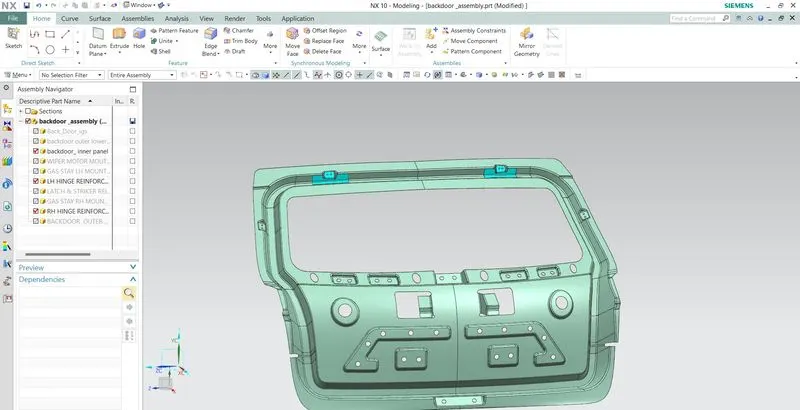
Now to assemble the back door with the vehicle Hinges are used to open and close the door. For that to increase the local area strength we have to design the emboss and provide the appropriate reinforcements to withstand the load acting upon it.
Spot welding:
Spot Welding is a form of resistance welding also known as Resistance Spot Welding (RSW). Spot Welding involves using heat produced by resistance to an electrical current to join materials together. The current heats the materials to a point where they become malleable. The use of strong pressure bonds them together.
Spot welding (also known as resistance spot welding) is a resistance welding process. This welding process is used primarily for welding two or more metal sheets together by applying pressure and heat from an electric current to the weld area.
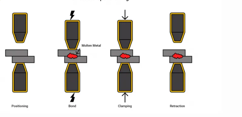
Spot welding occurs in a four-step process.
- Positioning: The material and electrode position so the operator may properly apply the bond.
- Bond: The bond applies, creating molten metal where the current meets.
- Clamping: The operator removes the current and keep the bond clamped in place.
- Retraction: The electrodes retract and the material cools.
Resistance spot welding
Important features used while designing:
- Wave Geometry Linker – With this you can create, associative or linked copies of any entity of a part into other parts. It may be a surface, edge, curve, body, sketch etc. The changes made to the original entity will be reflected in the copy of that entity.
- Extract Body – It is used to create an associative body by extracting faces, entire body or region of faces.
- Bridge Curve – It helps to create a tangent blend curve between two objects. The objects may be edges or sketch curves.
- Sew – It combines sheet bodies together by sewing their common edges. There shouldn’t be any gaps larger than specified tolerance.
- Projected Curve – It is used to project an existing curve/curves on a selected plane or surface by selecting a direction for projection.
- Trim Body – It is used to trim one or more bodies using a face or plane. You can also specify the bodies to retain and the bodies to discard.
- Offset Surface – It allows you to offset the surface below or upper from the original body.
- Offset Curve in Face – This command will allow to use offset the curve from a particular surface.
- Trim Sheet – It is used to trim off a portion of a sheet body using curves, faces, edges or planes.
- Through Curves mesh – It is used for a joing a body using primary and guide curves.
- Law Extension – This command extends a curve or edge to create a sheet body at desired angle length by changing the rules under angle law and length law.
- Trim and Extend – It helps you to trim and extend intersecting surfaces and make corner at their intersection.
- Face Blend – It creates fillets between faces.
- Edge Blend – It creates fillets on edges.
- Extend Sheet – It will allow you to extend an existing surface to required distance.
- Emboss – Emboss command creates an embossing by modifying a body with faces created by projecting a curve/section along a direction. You can modify the emboss using options like endcap location and draft angle.
- Mirror Geometry – it is used to mirror geometries about selected plane or surface.
- Thicken – It is used to convert a surface to solid body by adding some thickness.
OUTER PANEL (INNER/OUTER)
Outer panel of the rear door and is mostly responsible for aesthetics of the vehicle. Outer and inner panels are connected by mastic sealants in centre and by hemming process at edges. The outer door handle and in some cases, the number plates may also be installed on the outer panel of the back door. We have considered a 2-part outer panel for our design, outer upper panel and outer lower panel prospectively. Outer panel is manufacture by stamping sheet metal. Thickness for outer panel is 0.75mm
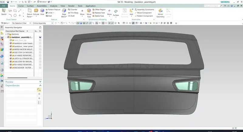
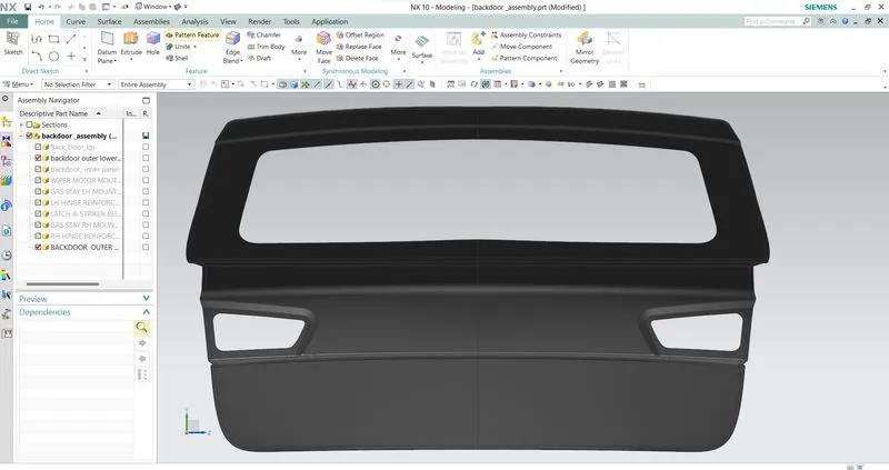
OUTER LOWER UPPER PANEL
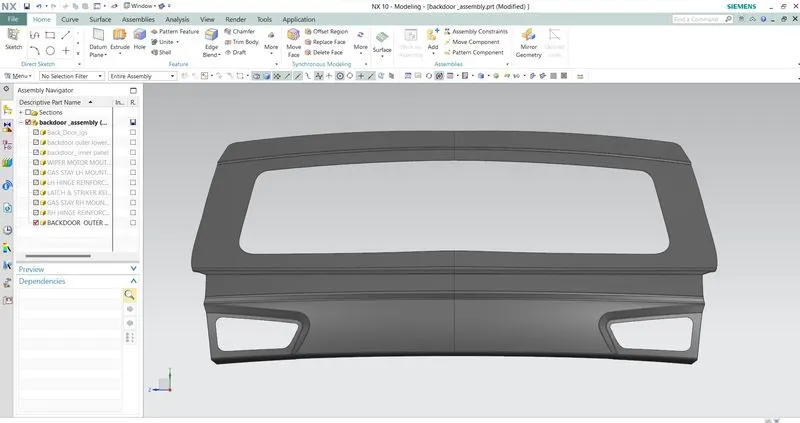
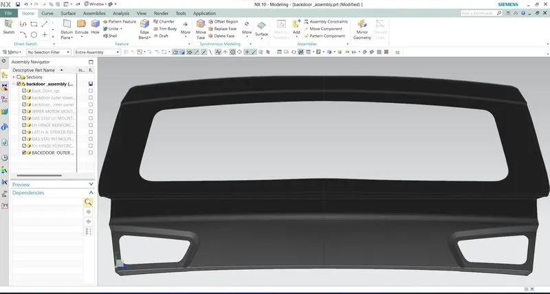
OUTER LOWER PANEL
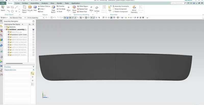
INNER PANEL
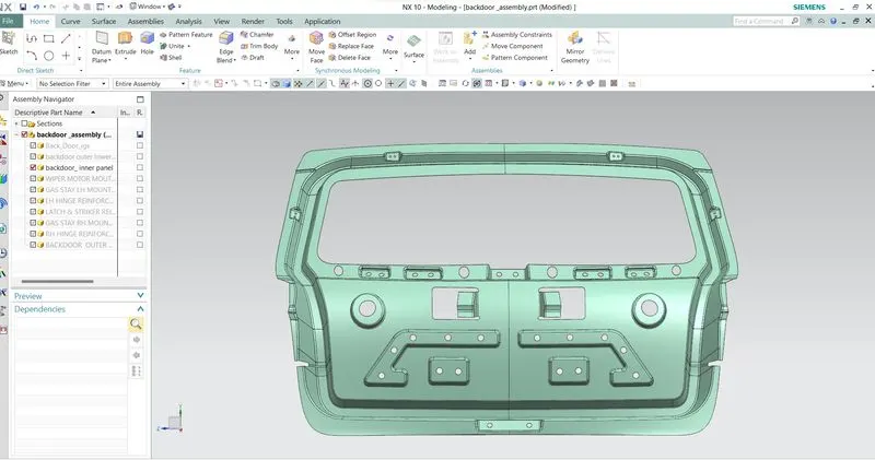
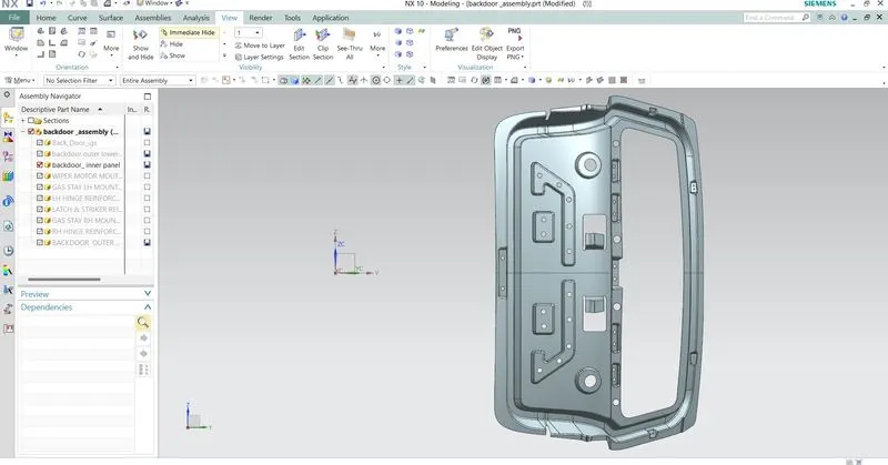
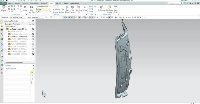
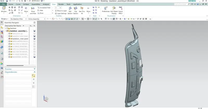
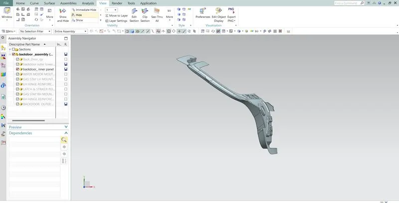
The inner panel of the door where most of the reinforcement and components are mounted. It is manufacture either by casting (aluminium) or sheet metal stamping (steel). Thickness of inner panel is 0.75mm
REINFORCEMENTS
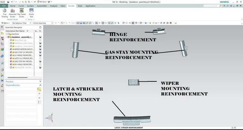
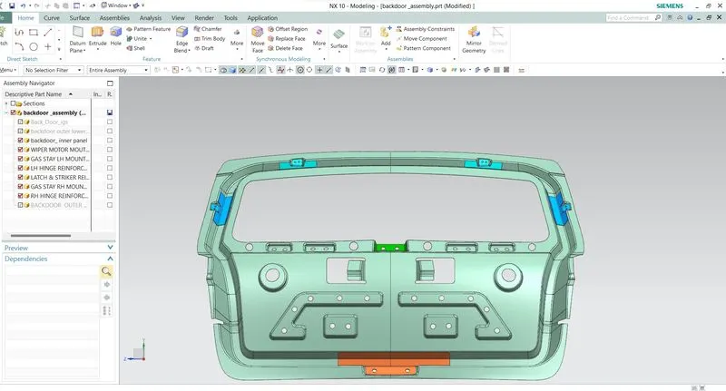
Reinforcements are provided to provide support and add extra material to the sheet metal part to increase its strength near component installation regions and minimize the impact of collisions. We have considered following reinforcement during our design. The reinforcement may be manufactured by stamping. Thickness of all reinforcement is 1.5mm.
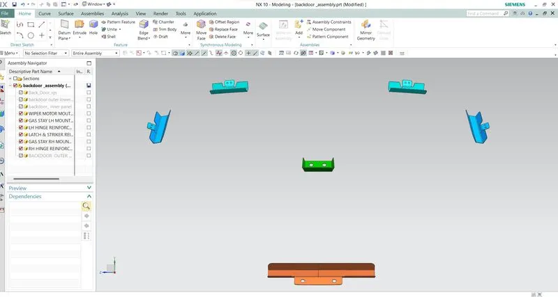
HINGES
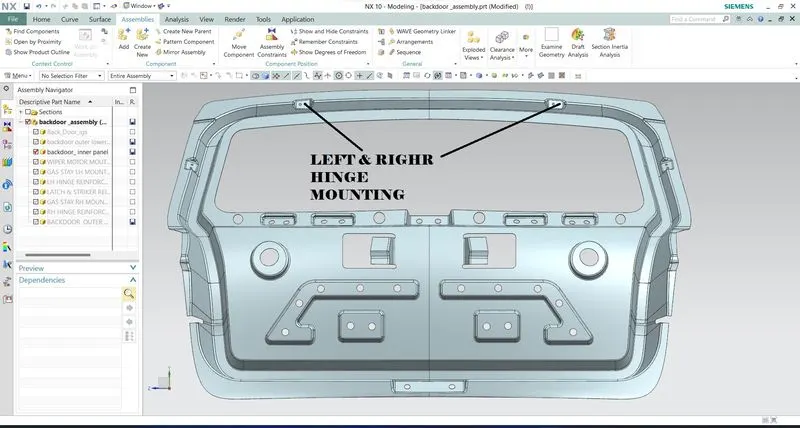
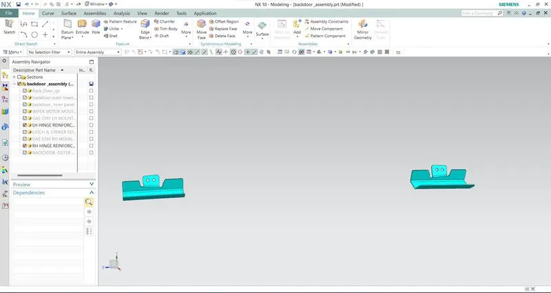
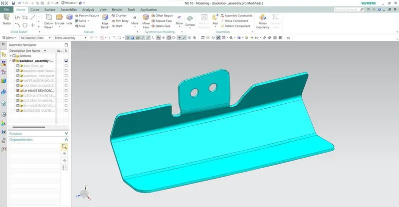
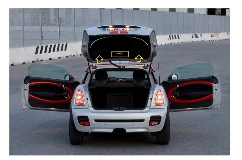
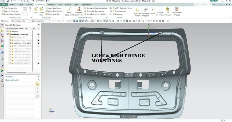
Hinges connect the door with the vehicle body and allow the door to rotate around a fixed axis for opening and closing movement. Generally, hinges are a 2-part assembly, where one part is bolted to door and other is bolted to vehicle body.
GAS STAY
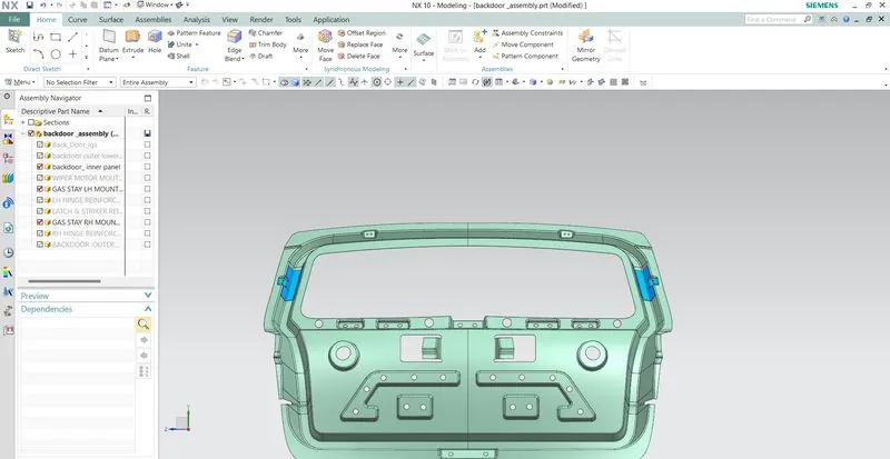
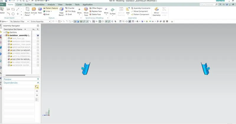
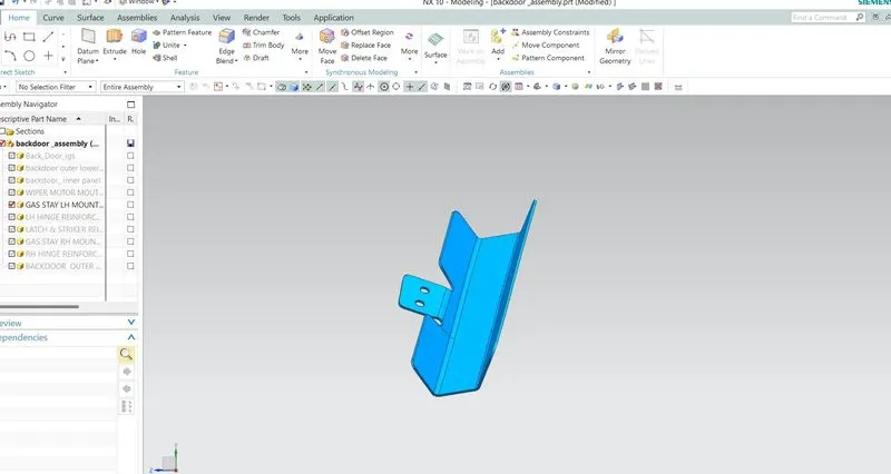
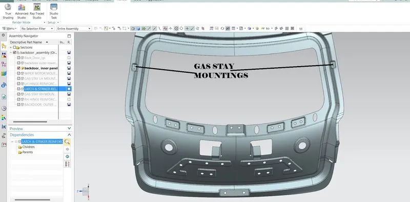
Gas stay is basically a gas spring that relies on elastic deformation of a compressed gas which is enclosed in a cylinder. It is used to reduce required effort while opening the back door. Although all the cars don’t come with gas stays, it may be required in case of a heavy back door.
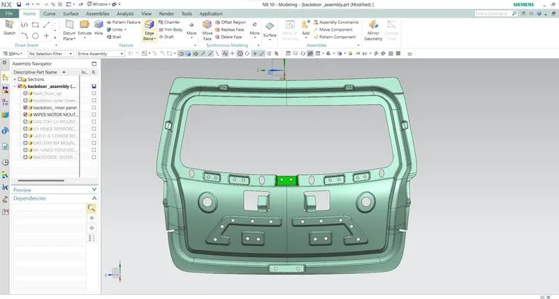
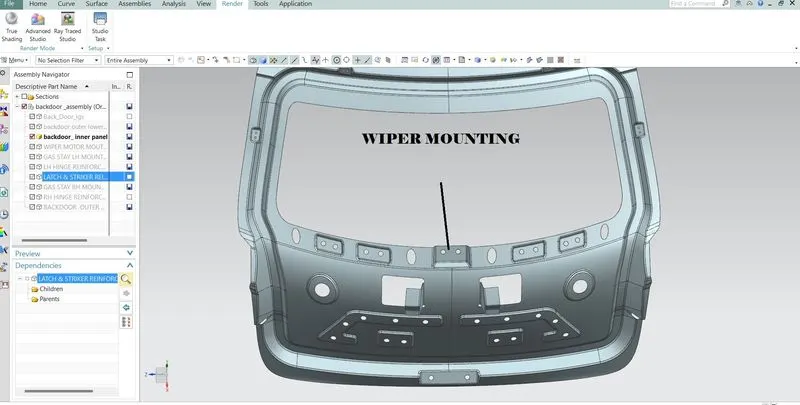
WIPER AND WIPER MOTOR MOUNTING
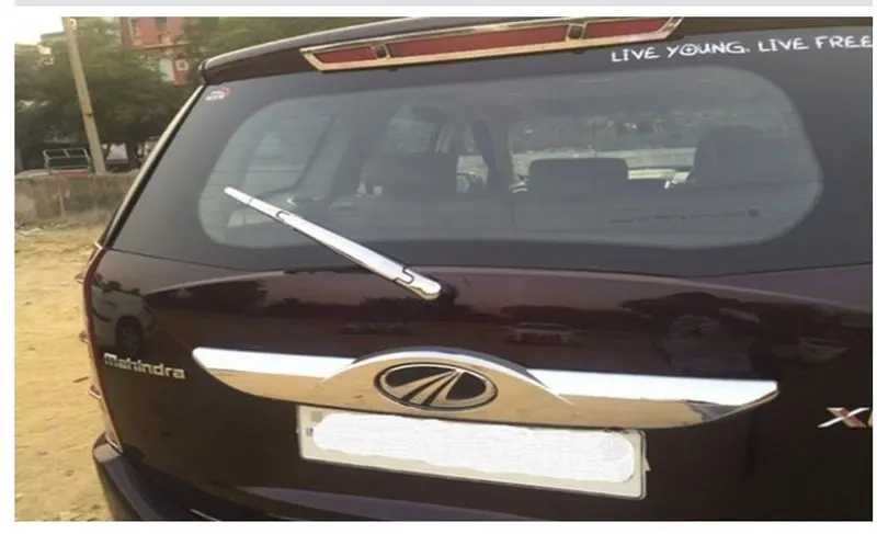
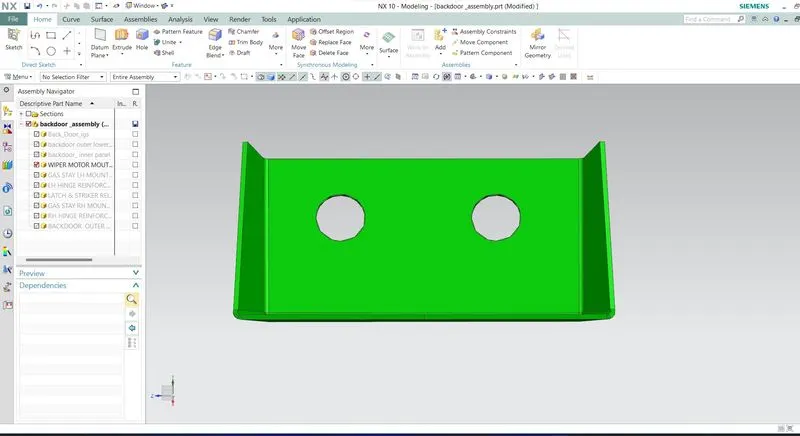
Wiper is used to wipe off the dust and water from the rear windscreen of the vehicle.
LATCH & STRIKER
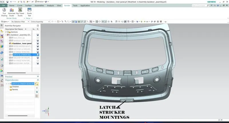
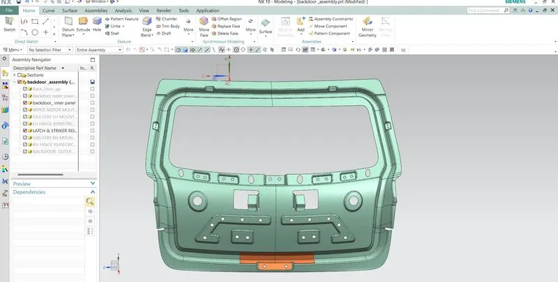
The position of the hinge should be perpendicular to the latch when the latch and striker meets for that a circle is draw from the centre of hinge axis to find the path of the striker and positioned it perpendicular to the path.
For the proper opening and closing of the door, the striker should be perpendicular to the trajectory of the door. For this, hinge is assembled at this position. Once it is placed, hinge axis is drawn.
- To check the hinge axis as the centre we draw a big circle to the position the latch in such a way that it is perpendicular to the hood trajectory.
- In between the two hinges the striker is perpendicular to the midpoint of two hinges, why because while closing and opening of the latch and striker the opening position be similar actions.
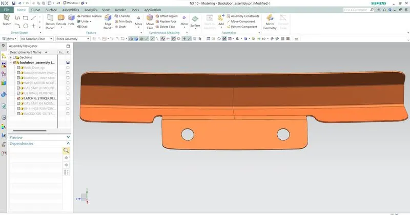
MASTIC SEALANTS
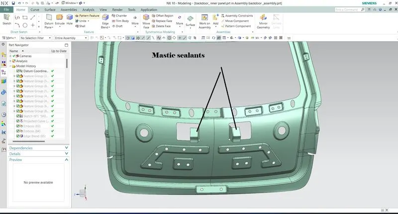
A Mastic sealant is a type of liquid sealant that cures in an elastic state, thus making it flexible while holding the bond of the surface that has attached together. It adheres to just about any material making an all-purpose type of sealant.
The main purpose of the outer panel is for the aesthetic looks. Thus, we cannot use bolts or welding. This has to be done with the help of the hemming and mastic sealants. Mastic sealants are elastic compound that behave like the rubber, it is placed between the outer and inner panel. Initially it is paste form, but after the hot furnace bath it gets hardened thus joining the outer and inner panel. Mastic sealant has the tendency to increase the strength of the panel and has influence of 80mm dia.
.
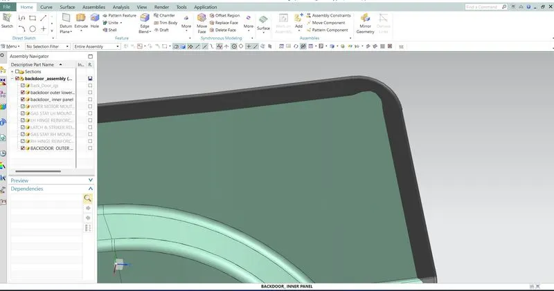
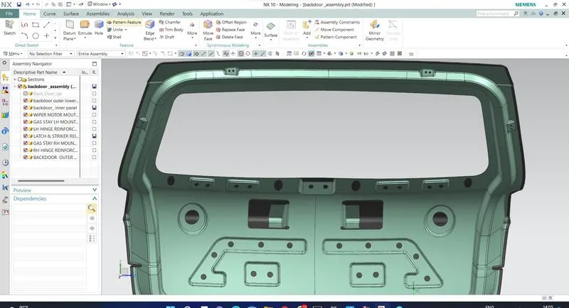
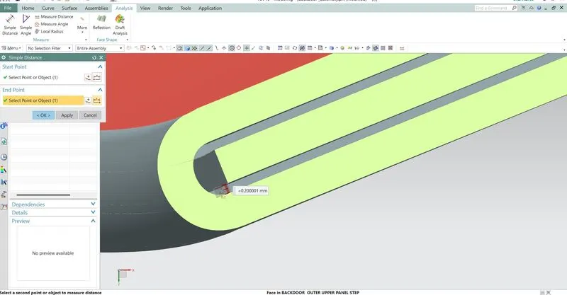
RELIFE
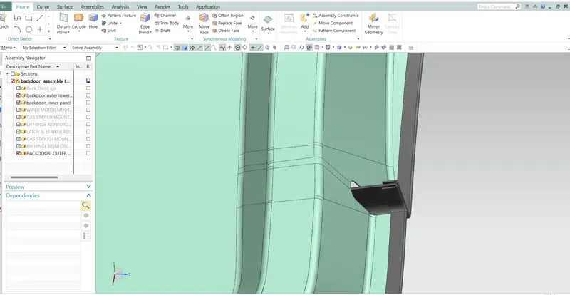
Relief is provided onto the part or component in order to remove any stress developed in a particular area i.e., sharp corners that takes place during the hemming process is carried out. Thus, corners are rounded or chamfered.
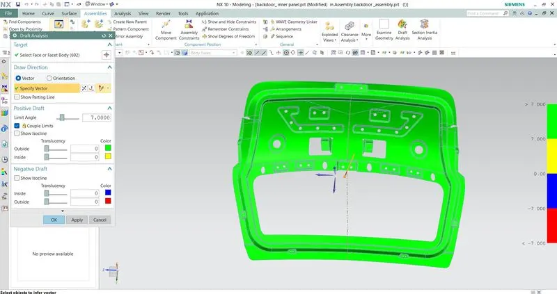
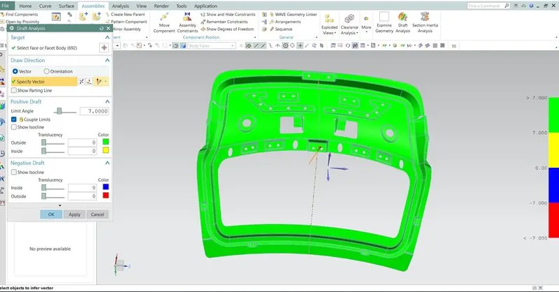
DRAFT ANALYSIS
No parts can be ejected from the tool if it is having a straight 90-degree profile from its base surface. A small draft angle is provided to each and every area of the component in order to get an easy removal of the component from the tool. Draft analysis technique is used to analyse whether our part model created in cad is manufacturing based on the draft condition applied. Here the part should get easily removed from the panel dies (in case of sheet metal part) or mold (in case of plastic). Here we are providing a direction in which component should eject in order to get an easy removal of component from the tool in other words it also lets us know whether the model is having a draft angle and how much is the draft angle from the tool direction.
For sheet metal: 7 degrees
For plastic component: 3 degrees
.
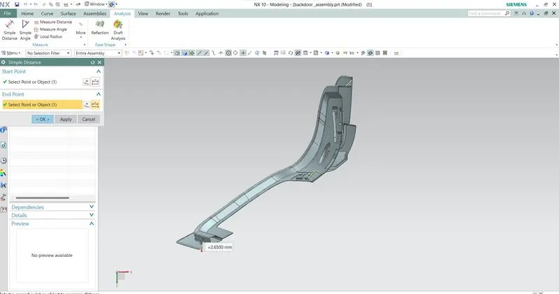
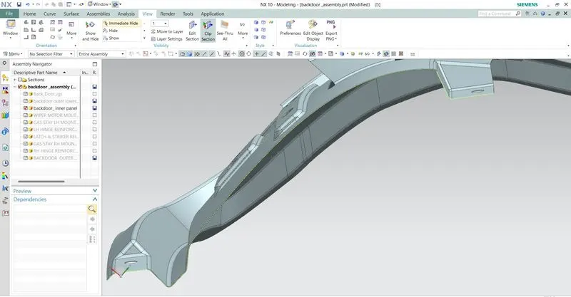
heming
ASSEMBLY
FRONT VIEW
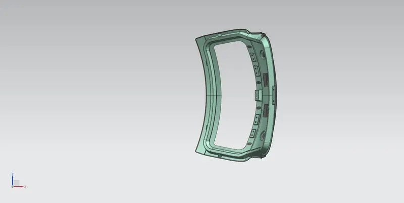
BOTTOM VIEW
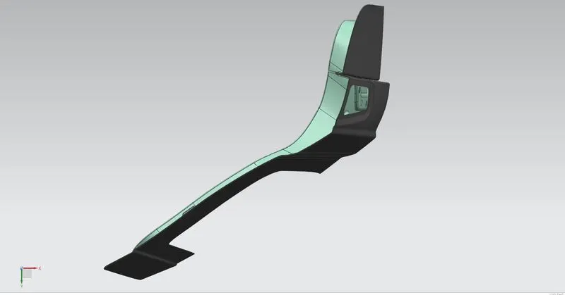
BACK VIEW
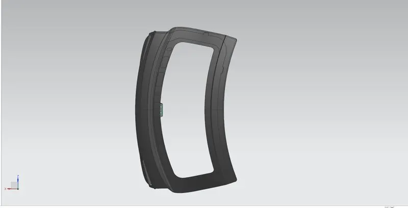
TOP VIEW
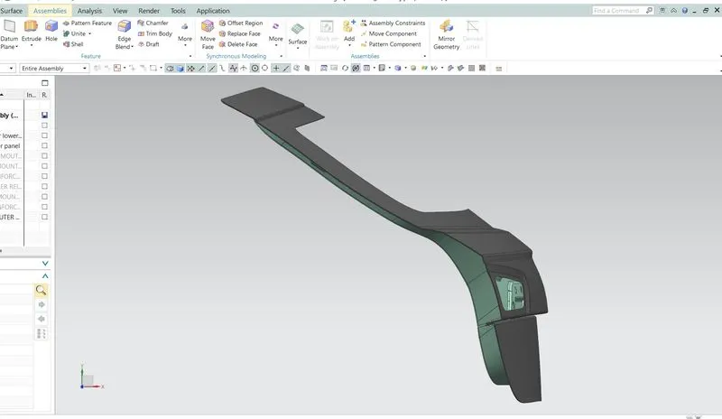
ISOMETRIC VIEW
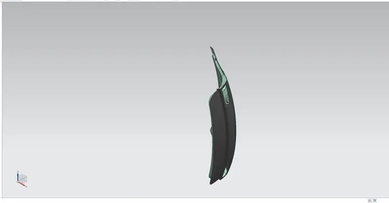
SIDE RIGHT VIEW
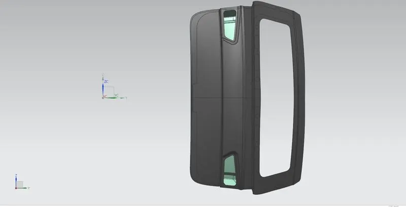
SIDE LEFT VIEW-
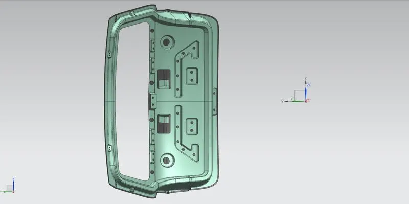
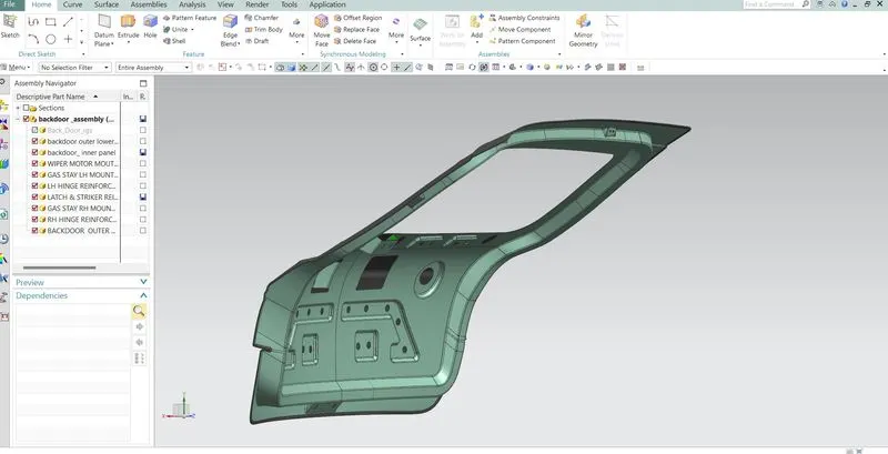
CONCLUSION
The back door outer and inner panel were designed with the help of the styling surface along the tooling direction.and
Draft analysis was performed on the inner panel and All the reinforcements were designed and placed at appropriate positions.