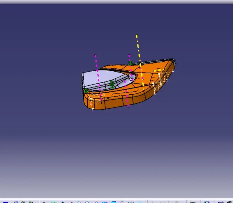
Week 12- Final project
OBJECTIVE
- Create the Door Trim Assembly from the given A Surface.
- Refer to the Master section for Nominal thickness, Flanges, and Heatstakes.
- Assemble the respective components into one single Product:
- Straight Arm Rest
- Inclined Arm Rest
- Upper Map
- Lower Map Pocket
- Lower Substrate
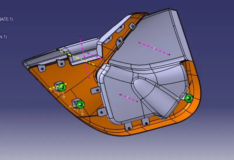
PROCEDURE
STEP 1: ASSIGNING A SURFACE and MASTER SECTIONS
| Visually | Using the Join option. This option is efficient but not effective. |
| Manually | Extracting the Boundary of the Class A surface. This option confirms better. |
- The Input file has a single Geometric set with all the surfaces of the Class A Door trim.
- We have to extract and assign the respective surfaces to each component.
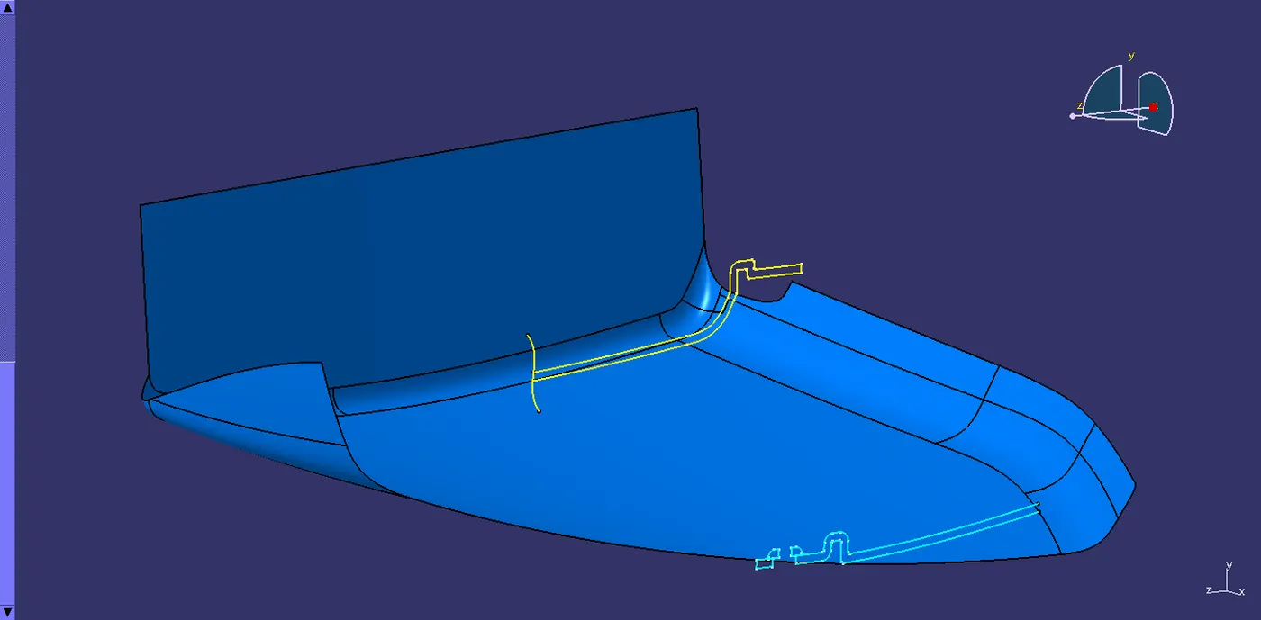
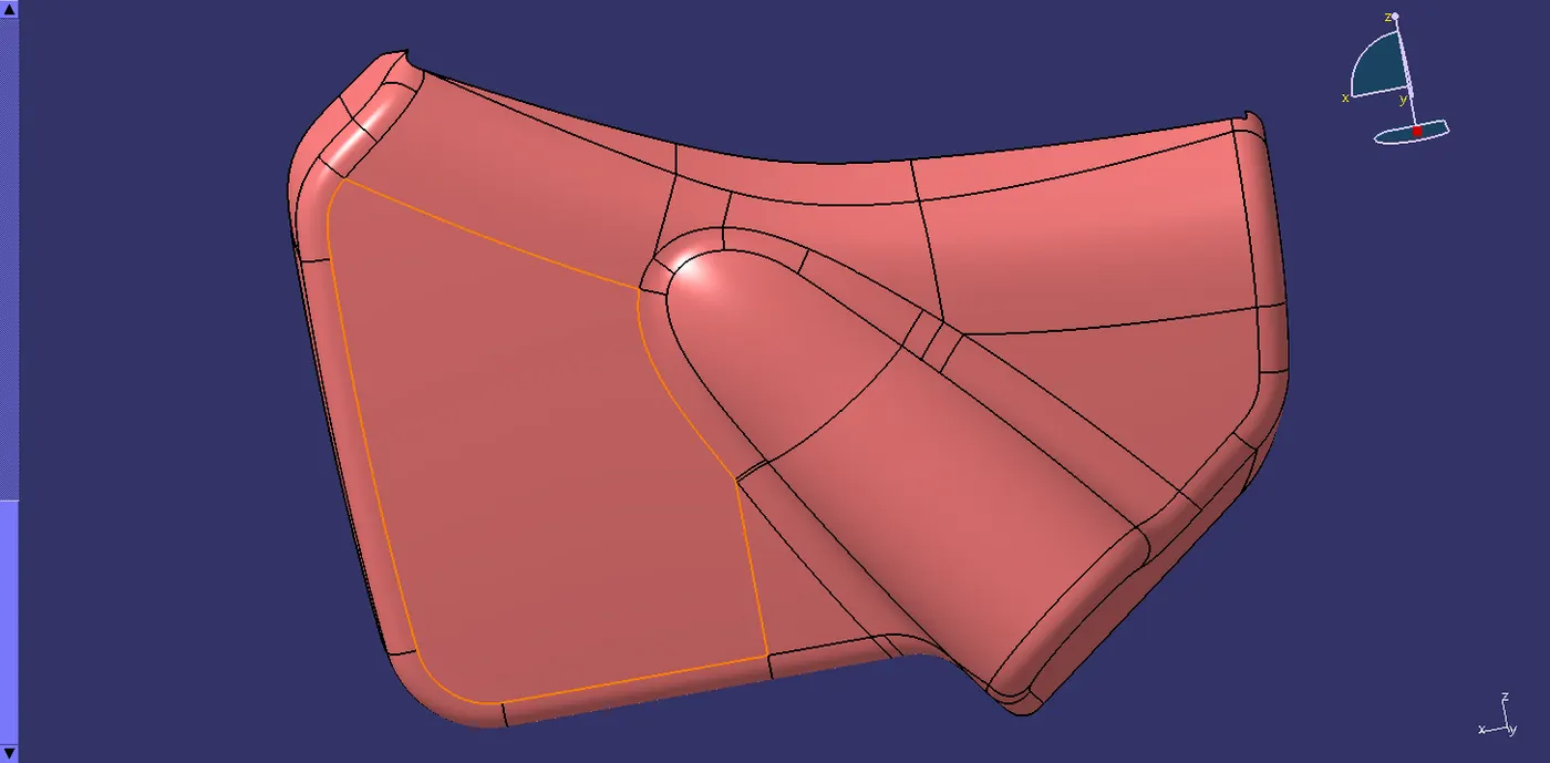
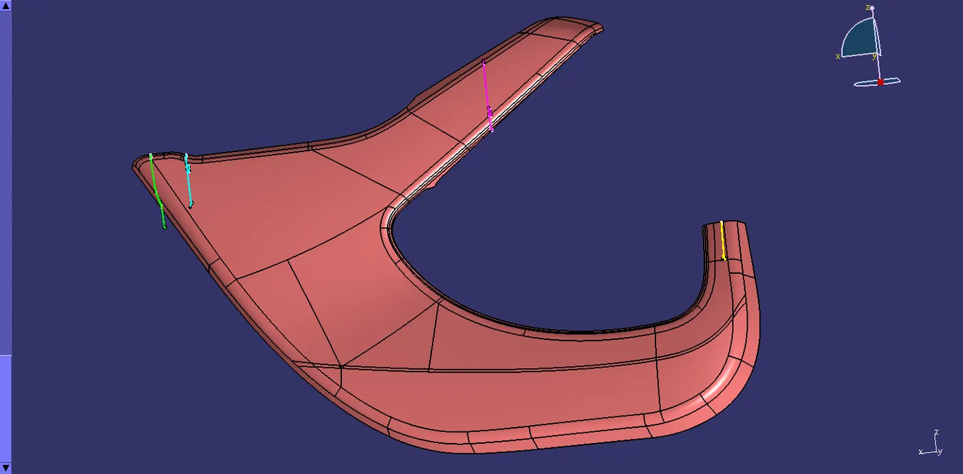
- We extract the A surface for the following components:
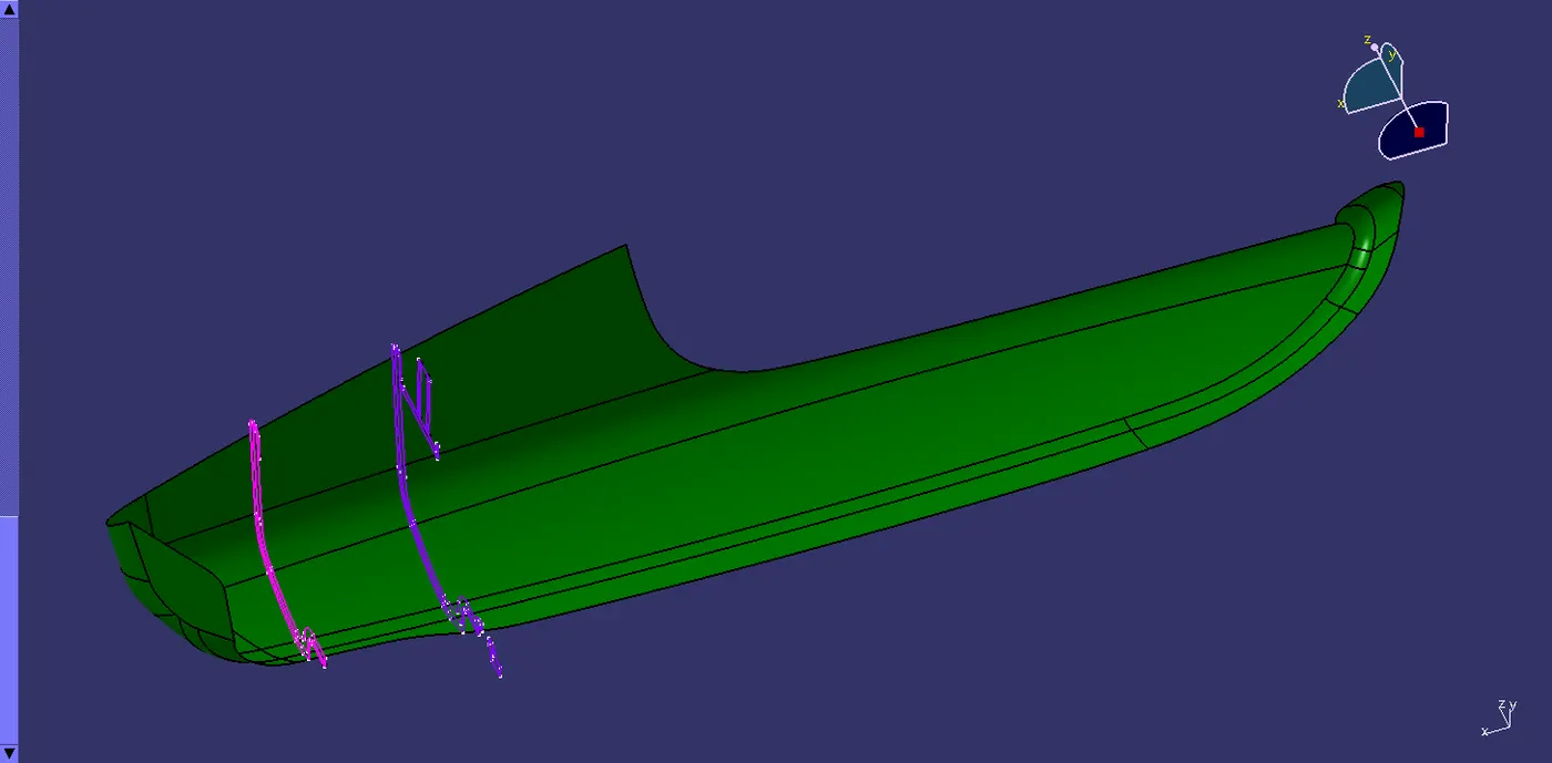
- Straight Arm Rest
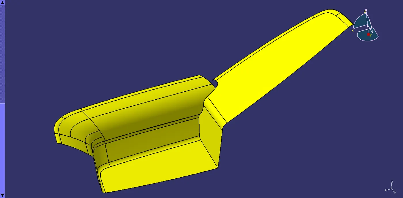
- Inclined Arm Rest
- Upper Map
- Lower Map Pocket
- Lower Substrate
| PART NO. | INSTANCE NAME | CLASS A | |
| PART 1 |
Straight Arm Rest |
 |
|
| PART 2 |
Inclined Arm Rest |
 |
|
| PART 3 |
Upper Map |
 |
|
| PART 4 |
Lower Map Pocket |
 |
|
| PART 5 |
Lower Substrate |
 |
STEP 2: CREATE ASSEMBLY
- Collect the parts inside one assembly (Create a New Product), by either of the options:
- Copy + Paste
- Add Existing Component
- Save Management:
- We cannot directly save the file by pressing Ctrl+S, because we have to organize the parts in the assembly file folder.
File > Save Management > Select the Parent Product > Save As (Create a separate folder) >
STEP 2: FIND THE TOOLING AXIS
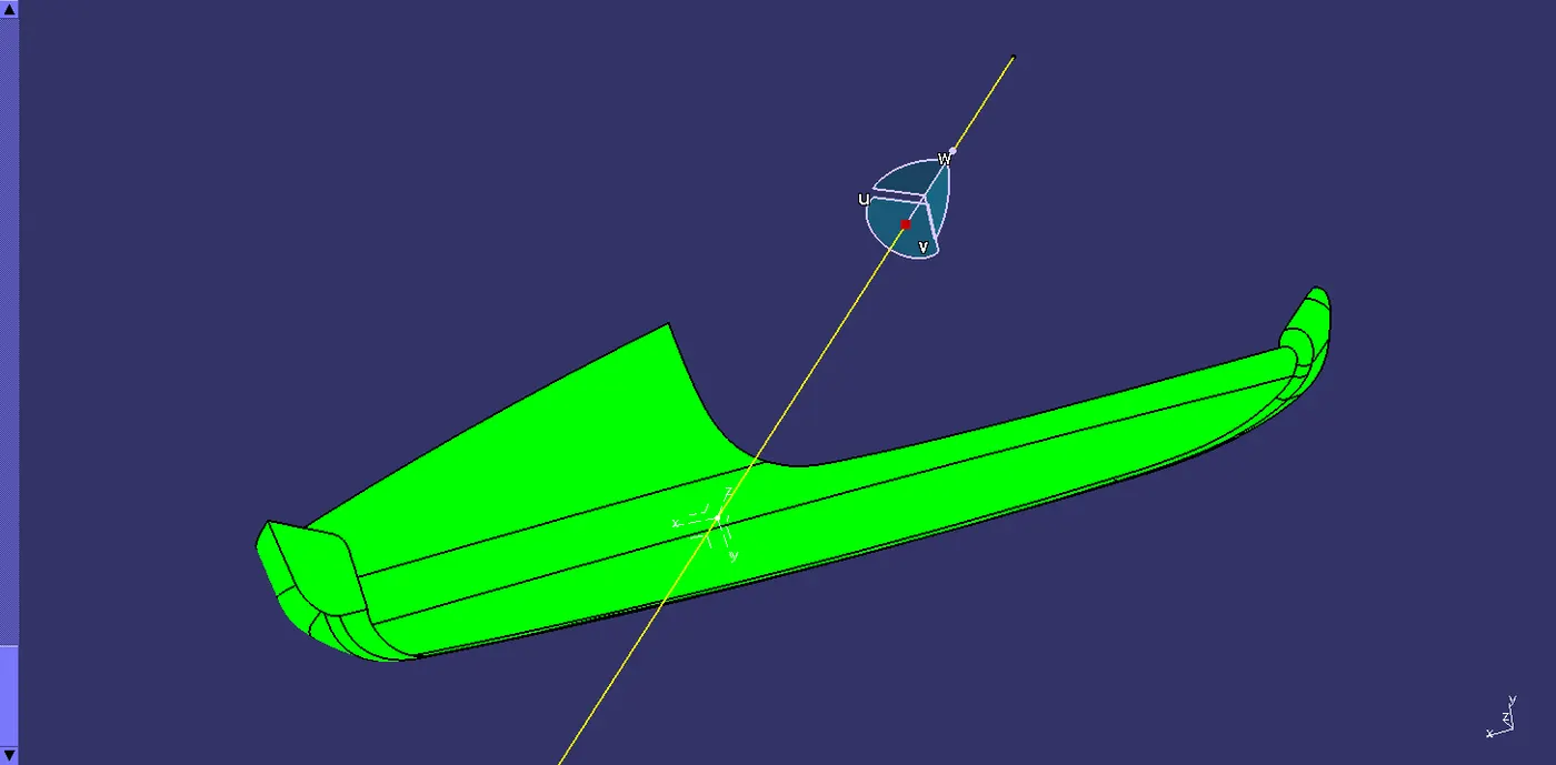
- Tooling Axis is the direction in which the Mold(Core-Cavity) travels perpendicular to the parting surface/line.
- Place the component on each plane (XY/YZ/ZX) and find the desirable tooling direction.
[Note: The plausible tooling axis is perpendicular to a Hole or large flat surface so look for those features when selecting.]
- So we need to create a midpoint on the plane perpendicular to the tooling axis.
| Holes | Use Multiple extracts to get the Boundary and define a midpoint using the "Curve/Circle" option. |
| Flat Surfaces | Extract the surface and then create a mid-point using the "On Surface" option. |
- Now, introduce an Axis system at the Midpoint. This will act as a reference coordinate system.
STEP 4: DRAW THE TOOLING/DRAFTING AXIS
- Due to the complexity of the geometry, the Bisecting method won't be accurate and also takes too much time and effort.
- Therefore, it is best to go with the Compass Method:
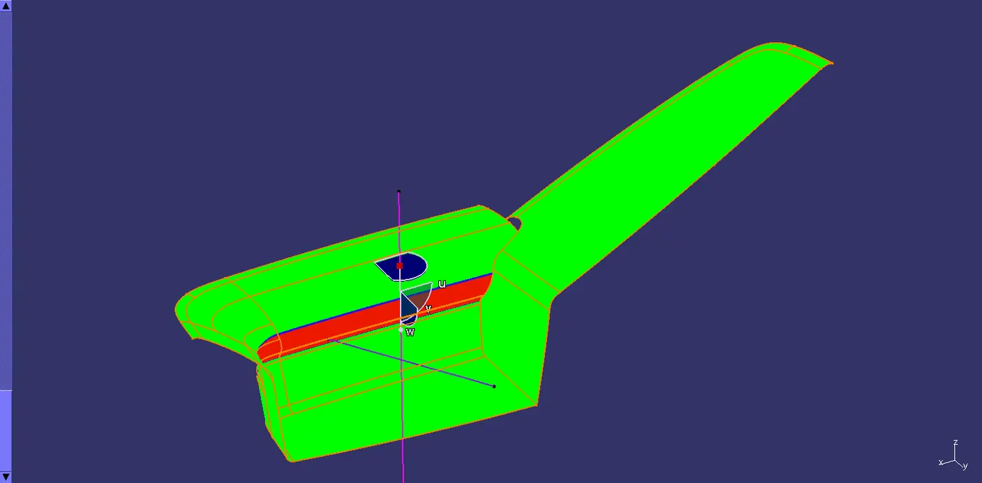
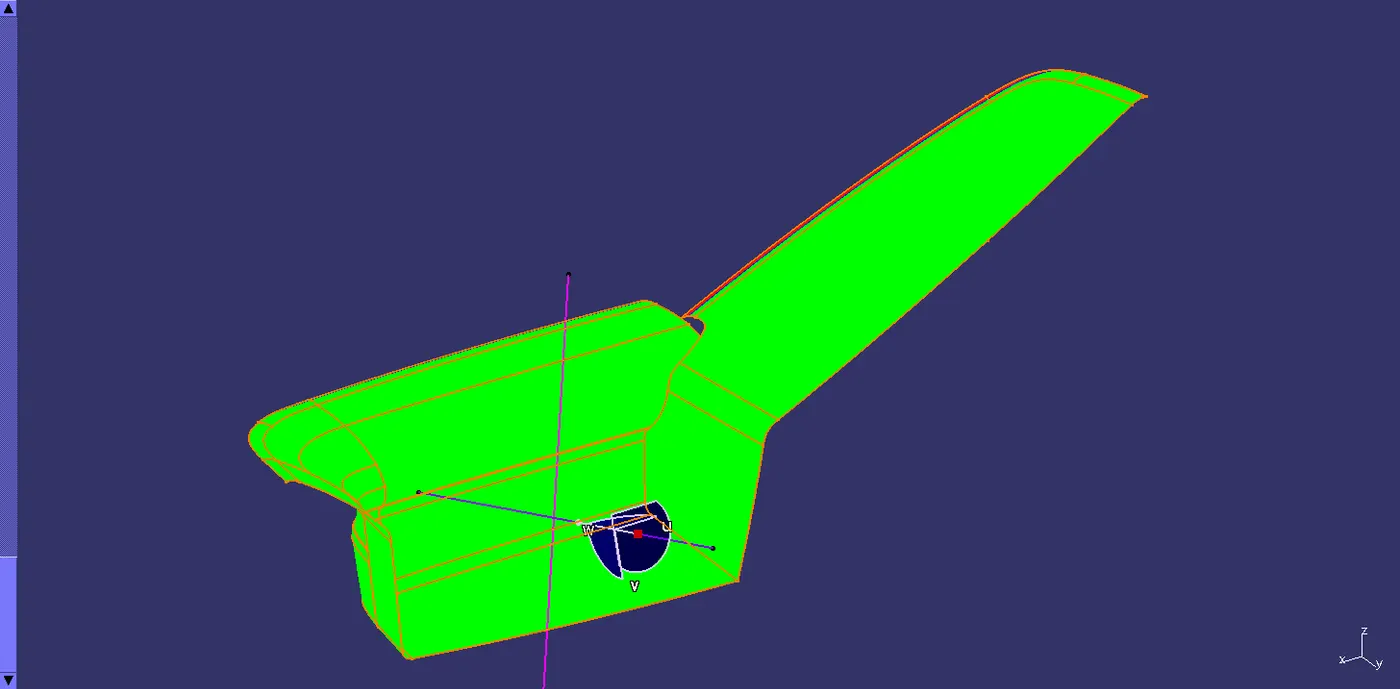
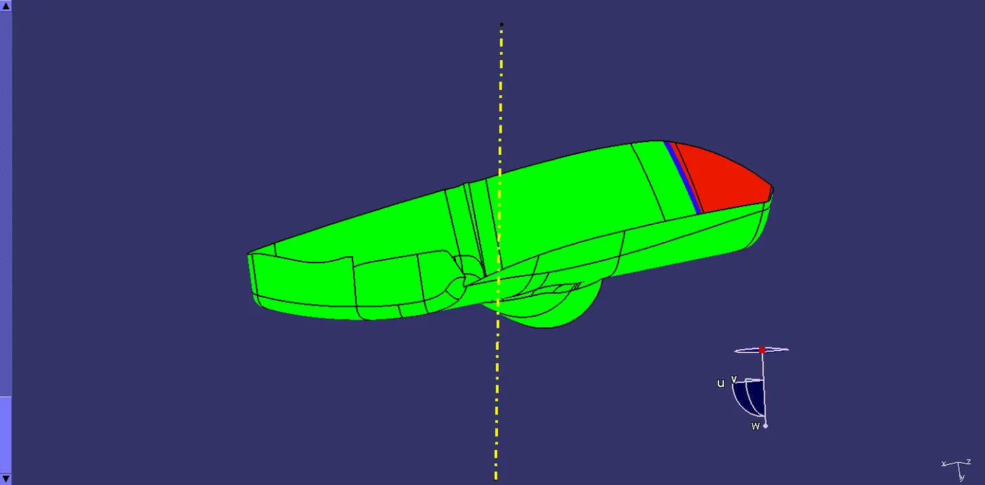
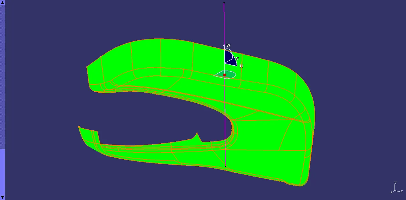
- Insert > Analysis > Feature Draft Analysis
- Simply place the compass on the largest flat surface.
- Check the Analysis.
- Tilt the Compass by Orientation or Rotation about an axis to get the desired result.
- After finalizing the orientation, lock the compass direction.
- Create a Line, this will be our Reference Axis:
- Line > Point-Direction > Select Point > Select Direction (Compass Direction)
| Colour | Description | Value |
| Green | Core Side | Above 3 degrees |
| Blue | Parting Line | 0 degrees |
| Red | Cavity Side | Below 0 degrees |
| PART NO. | INSTANCE NAME | MAIN TOOLING | SIDE TOOLING | ||
| 1 |
Straight Arm Rest |
 |
|||
| 2 |
Inclined Arm Rest |
 |
 |
||
| 3 |
Upper Map |
 |
|||
| 4 |
Lower Map Pocket |
 |
|||
| 5 |
Lower Substrate |
 |
ADVANTAGE OF COMPASS METHOD:
We can define the Tooling direction and conduct a draft analysis simultaneously from within the "Feature Draft Analysis" Tool.
NOTE:
- If there are no flat surfaces, then use the "Measure Inertia" tool to get the Centre of Gravity and the Axis System for the selected complex geometry.
- If some regions fail for draft analysis, then we have to introduce a Lifter/Side Core as well.
STEP 5: A SURFACE FLANGES
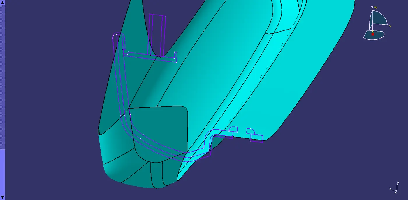
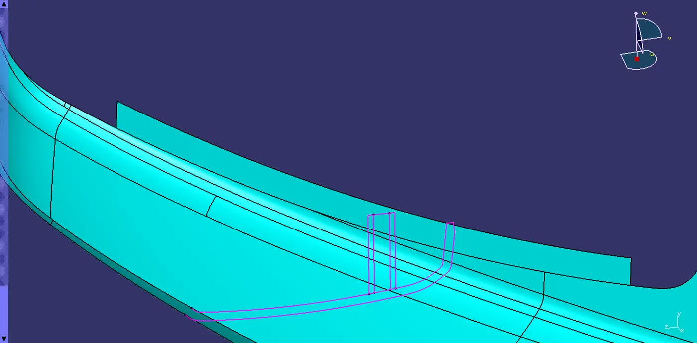
- From the given Master section, we have to create the Flanges and join/trim them with the A surface input to create one single Entity.
- Operations performed in creating Flanges:
| EXTRACT | |
| SWEEP | |
| EXTRAPOLATE | |
| TRIM/SPLIT | |
| JOIN |
- The newly edited A surface with Flanges will be our new input for creating the Solid component.
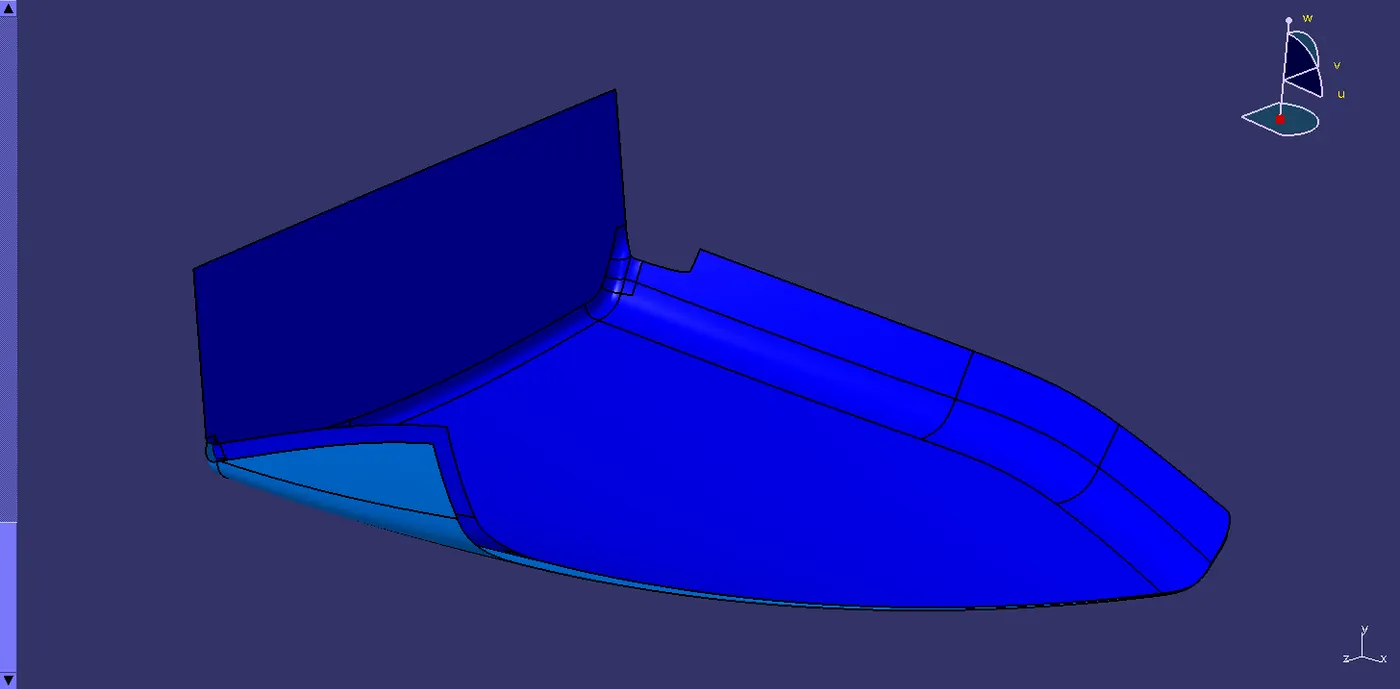
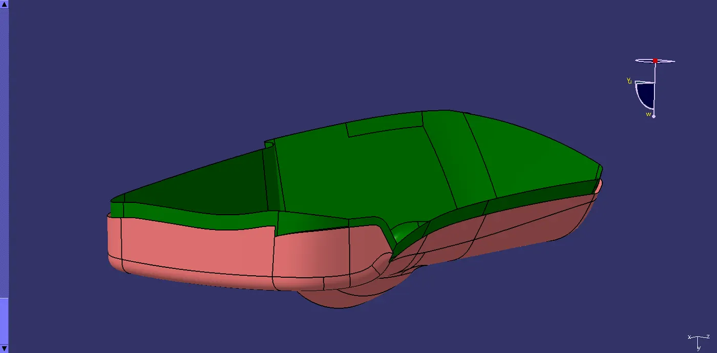
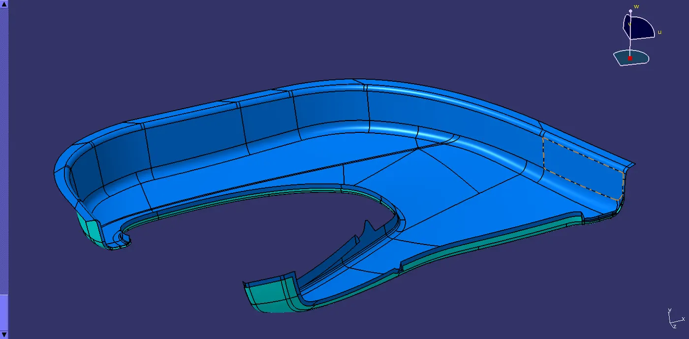
STEP 6: B SURFACE CREATION
Note: Depending on the geometry, the extraction and offset of the fillets might generate non-uniform thickness. So it is advisable to extract only the flat surfaces and then apply fillets at the end of Class B formation.
Perform the following operations in the order:
| EXTRACT | Choose the respective A surface and extract with no propagation option. |
| UNTRIM | The extracted surface will possess the specific trimmed. Untrim to get the basic geometry. |
| EXTRAPOLATE | The surfaces have to overlap each other in order to facilitate trimming therefore extrapolate it up to the required dimension. |
| TRIM | Trim the surfaces according to the required geometry. |
| OFFSET |
Note: Offset the Silent Fillet separately and then trim with the bucket
|
| FILLET |
|
Note: The fillet radius of the Class B offset is altered to maintain the uniform thickness throughout the geometry.
| Offset direction | Fillet Radius |
| Inward | Initial Radius - Thickness |
| Outward | initial Radius + Thickness |
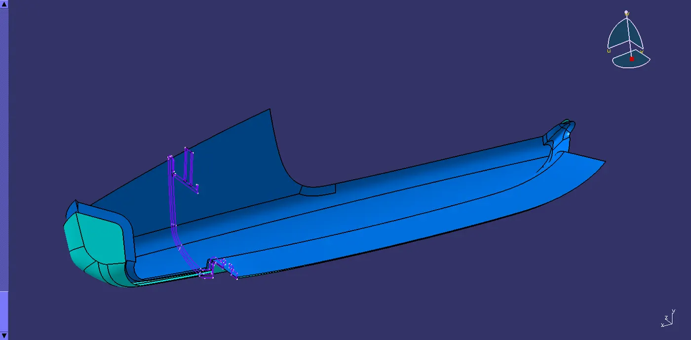
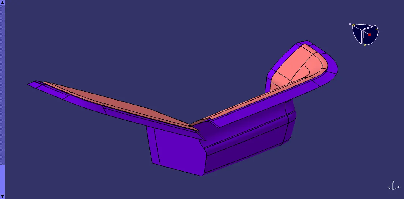
| PART NO. | INSTANCE NAME | B SURFACE | |
| 1 |
Straight Arm Rest |
 |
|
| 2 |
Inclined Arm Rest |
 |
|
| 3 |
Upper Map |
 |
|
| 4 |
Lower Map Pocket |
 |
|
| 5 |
Lower Substrate |
 |
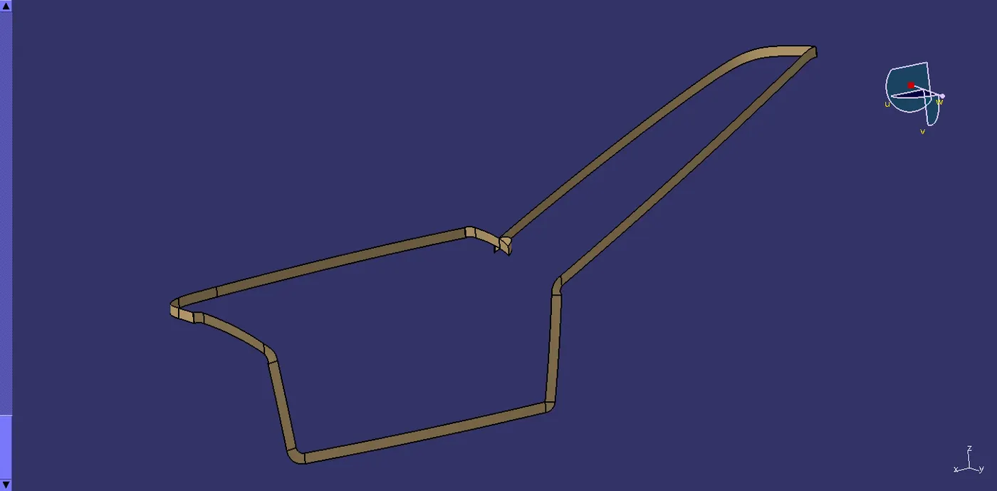
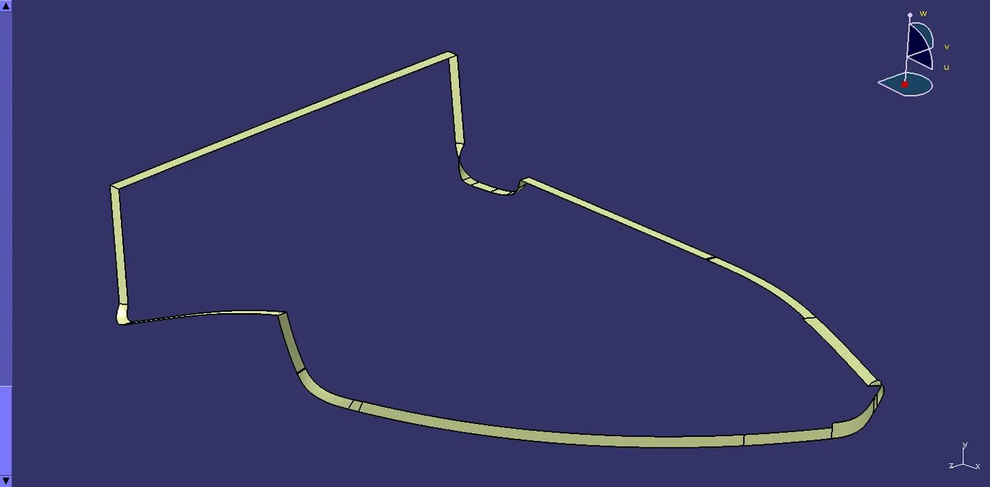
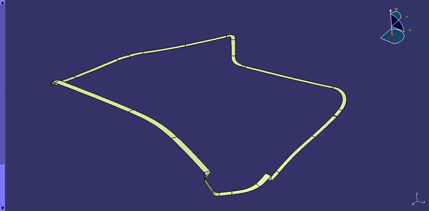
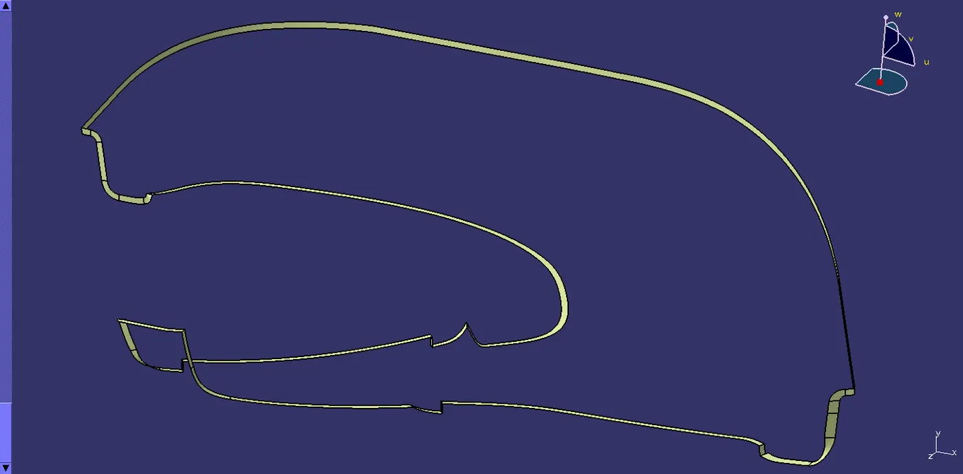
STEP 7: C SURFACE CREATION
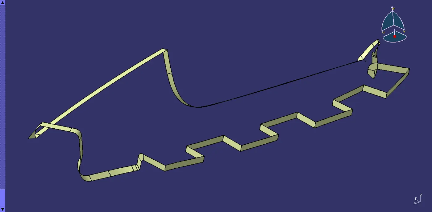
C surface is the part of the geometry that connects Class A with B surface.
Rules to be followed. for C surface creation:
- A minimum draft of 3 degrees should be provided to facilitate the Ejection of the Molded component.
- The parting line should be on the B surface. This means that the draft should sweep outwards, from the C surface.
Perform the following operations in the order:
| MULTIPLE EXTRACT | Extract only the Boundary by Tangential selection. |
| CURVE SMOOTH | We need minimum Parting lines as possibles, so smoothen the extracted boundary. |
| SWEEP |
The C surface is swept with the Line option along the Drafting Angle Direction.
|
| MULTI-SECTIONS SURFACE |
In places like Fillets where the Sweep option doesn't work, we can fill in the gap using MSS.
|
| EXTRAPOLATE |
The Sweeps at the edges need to overlap in |
| JOIN | For our future reference, we can Join all the C surface sweeps as one single entity. |
| PART NO. | INSTANCE NAME | C SURFACE | |
| 1 |
Straight Arm Rest |
 |
|
| 2 |
Inclined Arm Rest |
 |
|
| 3 |
Upper Map |
 |
|
| 4 |
Lower Map Pocket |
 |
|
| 5 |
Lower Substrate |
 |
STEP 8: CLOSED SURFACE
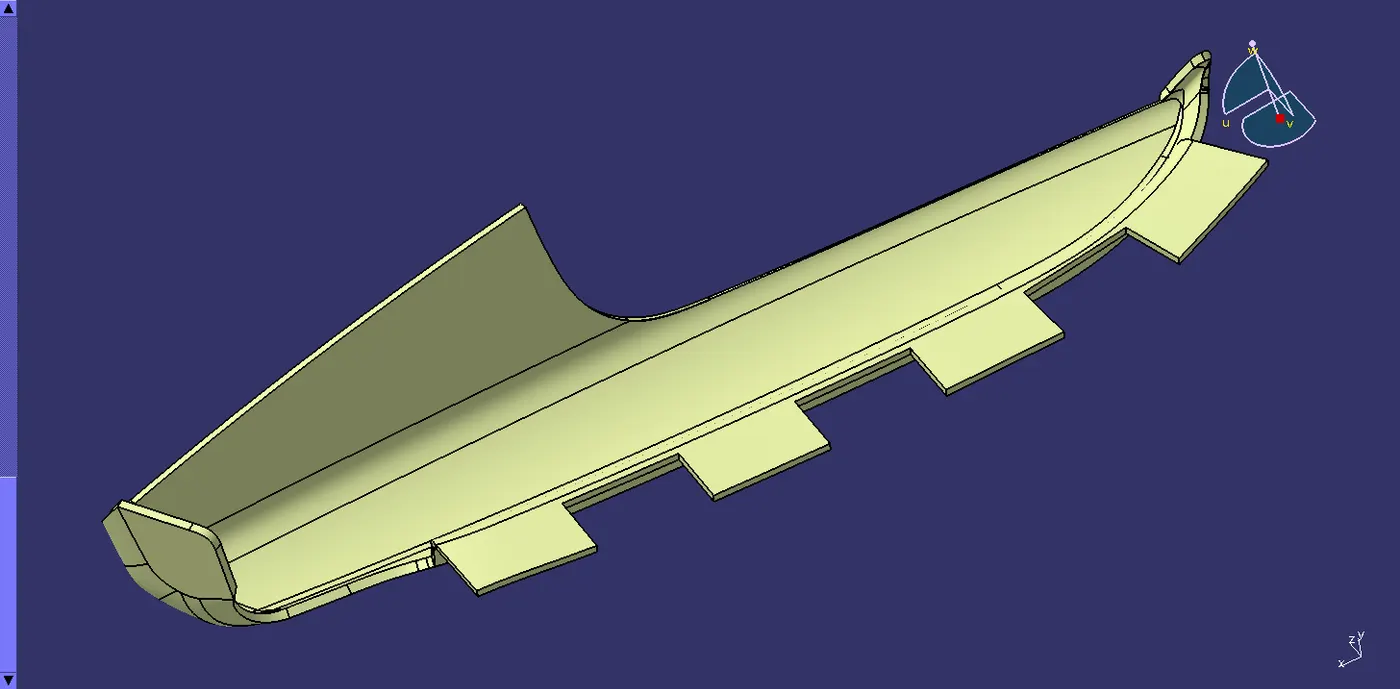
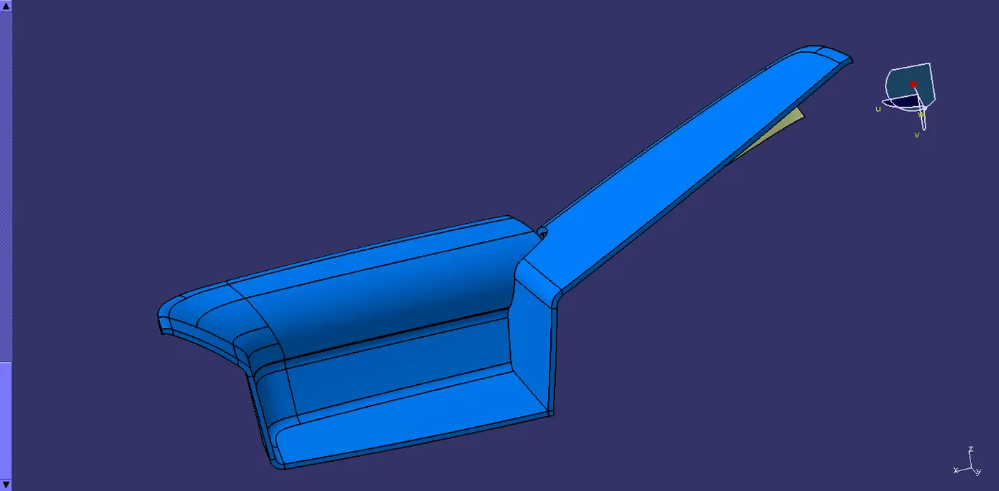
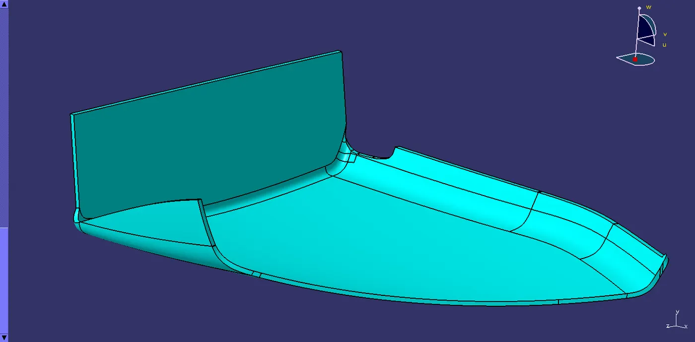
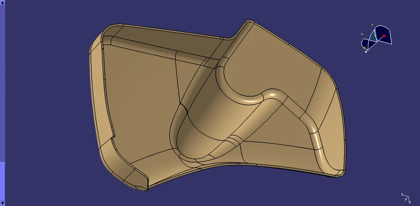
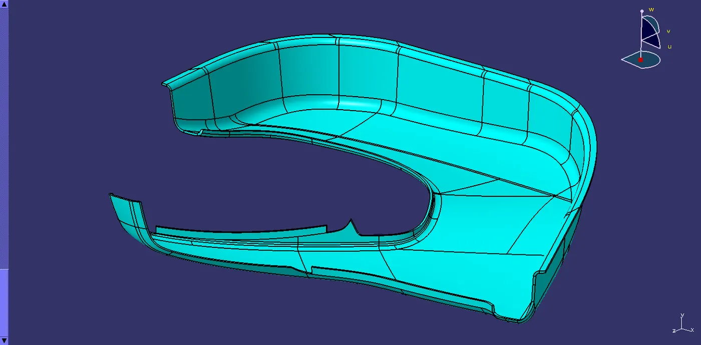
- First Trim/Join Class A with Class C.
- Then Trim with Class B and keep the respective surfaces.
| PART NO. | INSTANCE NAME | CLOSED SURFACE | |||
| 1 |
Straight Arm Rest |
 |
|||
| 2 |
Inclined Arm Rest |
 |
|||
| 3 |
Upper Map |
 |
|||
| 4 |
Lower Map Pocket |
 |
|||
| 5 |
Lower Substrate |
 |
STEP 9: CLOSED BODY DRAFT ANALYSIS
All the 3 class surfaces must pass in this analysis.
Insert > Analysis > Feature Draft Analysis
Note: Ensure you have the Material view mode ON.
- Define the Draft direction using the "Compass" option.
- Drag the Axis system representation close to the model and align it along the tooling axis.
- "Lock" the Draft direction.
- Set the Colour scale
| Colour | Description | Value |
| Green | Core Side | Above 3 degrees |
| Blue | --- | 0 degrees |
| Red | Cavity Side | Below 0 degrees |
- Place the Analysis Tool (Arrow Icon) anywhere on the model and review the colours on the feature.
- If any feature (especially C surface) is showing Blue/Red then choose the same option again (It will switch to Analysis under Running point) and place it on the respective feature to review the deviation of the sweep angle from the Tooling Axis.
STEP 10: PLASTIC FEATURE: DOG HOUSE
DEFINITION
- It is a feature used:
- To avoid sink marks.
- Solve length issue.
- Provide strength and assembly.
DESIGN GUIDELINES FOR DOG HOUSE
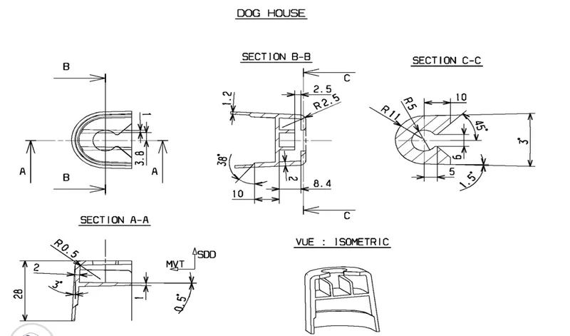
| Draft |
|
| Width |
|
| Sink Saver |
|
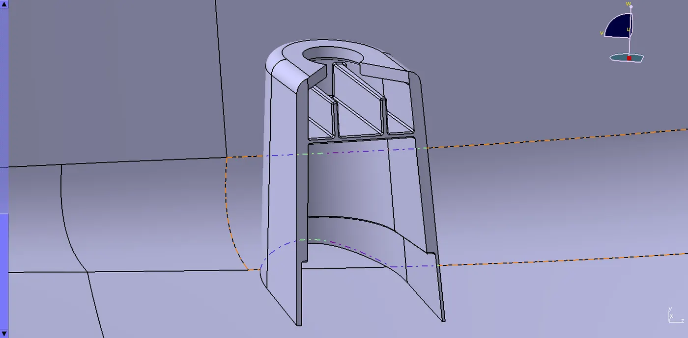
Operations performed for creating Doghouse:
| 1.1 | Extrude |
|
| 1.2 | Trim |
|
| 1.3 | Thickness |
|
| 1.4 | Draft |
|
Operations performed for creating Sink Saver:
| 2.1 | Multiple Extract |
|
| 2.2 | Extrapolate |
|
| 2.3 | Offset |
|
| 2.4 | Split |
|
| 2.5 | Fillet |
|
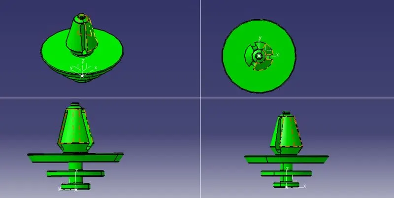
STEP 11: PLASTIC FEATURE: PUSH PIN
DEFINITION
- It is a feature that facilitates:
- Locating and Arresting components of an Assembly.
- Providing Alignment in Mating Parts.
- Acting as a stopper or guide for various mechanisms.
DESIGN GUIDELINES FOR PUSH PIN
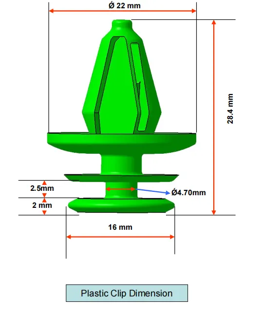
Operations to be followed:
| Positioned Sketch |
|
| Revolve/Shaft |
|
| Pad |
|
| Boolean Remove |
|
| Chamfer | |
| Fillet |
|
STEP 12: PLASTIC FEATURE: HEAT STAKE
GUIDELINES FOR HEAT STAKE DESIGN
| Diameter |
|
| Thickness |
|
| Height |
|
| Draft |
|
| Flat plate |
|
| Clearance |
|
| Spacing |
|
GUIDELINES FOR RIB DESIGN TO SUPPORT HEAT STAKES
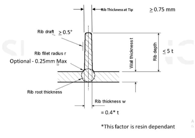
| Draft |
|
| Thickness |
|
| Fillet |
|
| Height |
|
| Base Rib Root Dia |
|
Operations to be followed:
| Extrude |
|
| Thickness |
|
| Draft |
|
| Boolean |
|
| Fillet |
|
STEP 13: TRANSLATION OF PLASTIC FEATURES
- After creating a single feature, we can translate it multiple times to the desired location.
- First Copy the respective feature's part body into the main part file:
- Copy > Paste Special > As specified in Part Document
- This removes the Parent-Children relationship and we can edit the translated part according to our needs.
STEP 14: BOOLEAN OPERATION
- We have to add all the translated features to the Main body of the Substrate.
- The Union Trim operation fit the best option for our needs.
- Define the Main part body as the Working Object.
- Select Feature Body > Union Trim > Select Faces to remove/keep
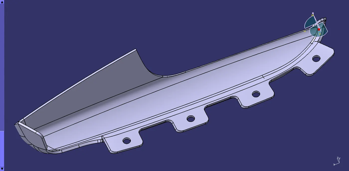
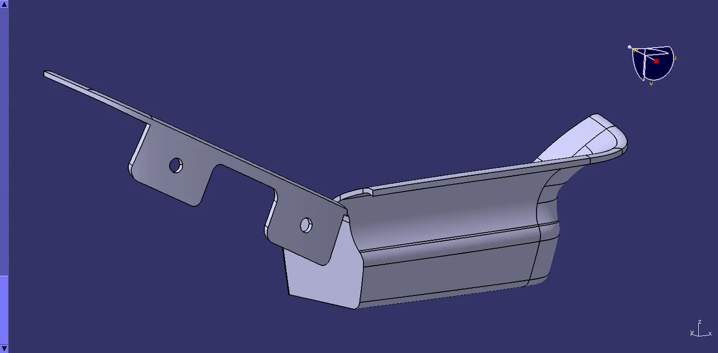
STEP 15: CLEARANCE FOR HEAT STAKES PROVIDED ON FLANGES
- The door trim Assembly has to be rigidly fixed as one unit.
- The 4 components will be permanently arrested to the Lowered substrate by using the Heastakes.
- The Heatstakes will pass through the flanges of the components, therefore some clearance of 0.1mm has to be provided.
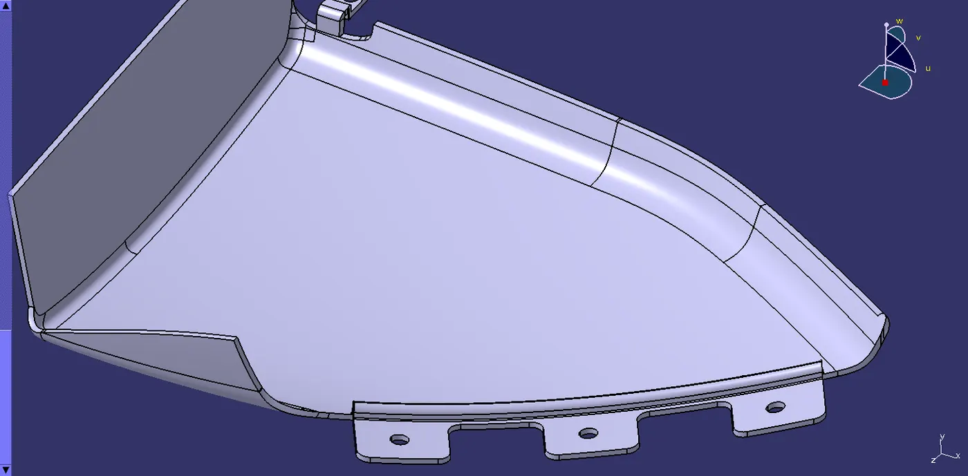
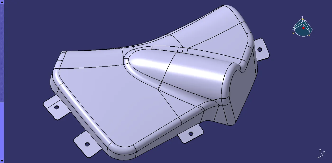
| PART NO. | INSTANCE NAME | FLANGES WITH CLEARANCE | |
| 1 |
Straight Arm Rest |
 |
|
| 2 |
Inclined Arm Rest |
 |
|
| 3 |
Upper Map |
 |
|
| 4 |
Lower Map Pocket |
 |
|
| 5 |
Lower Substrate |
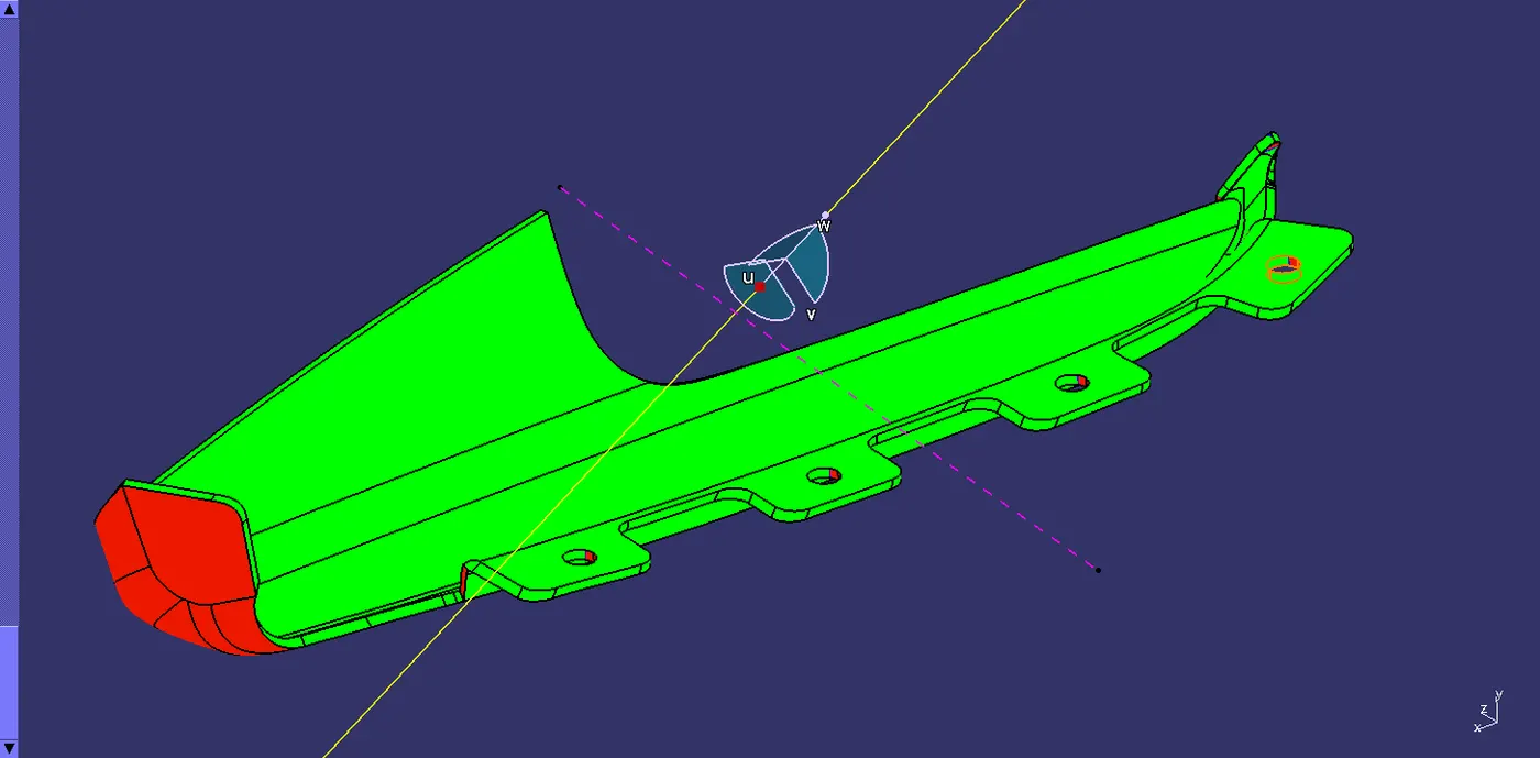
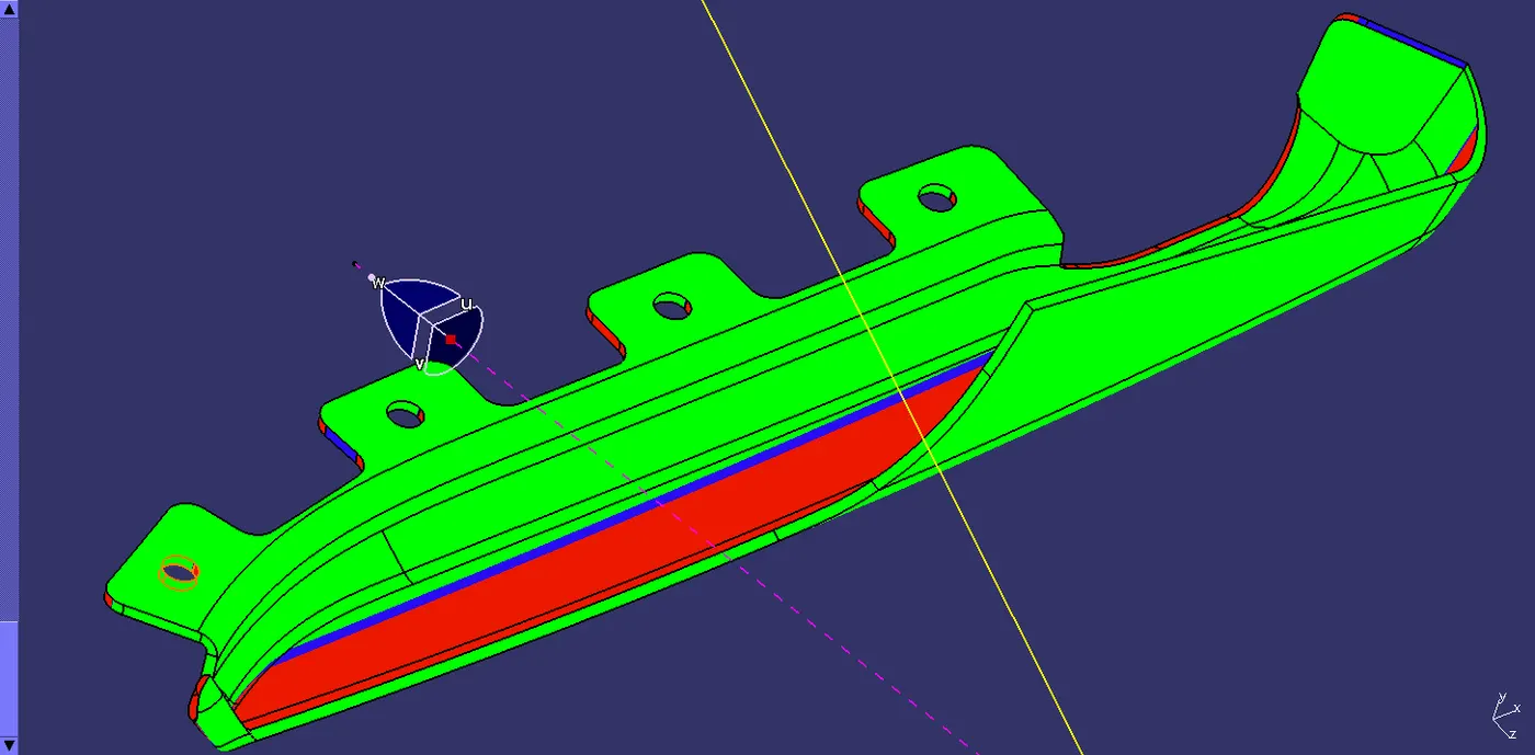
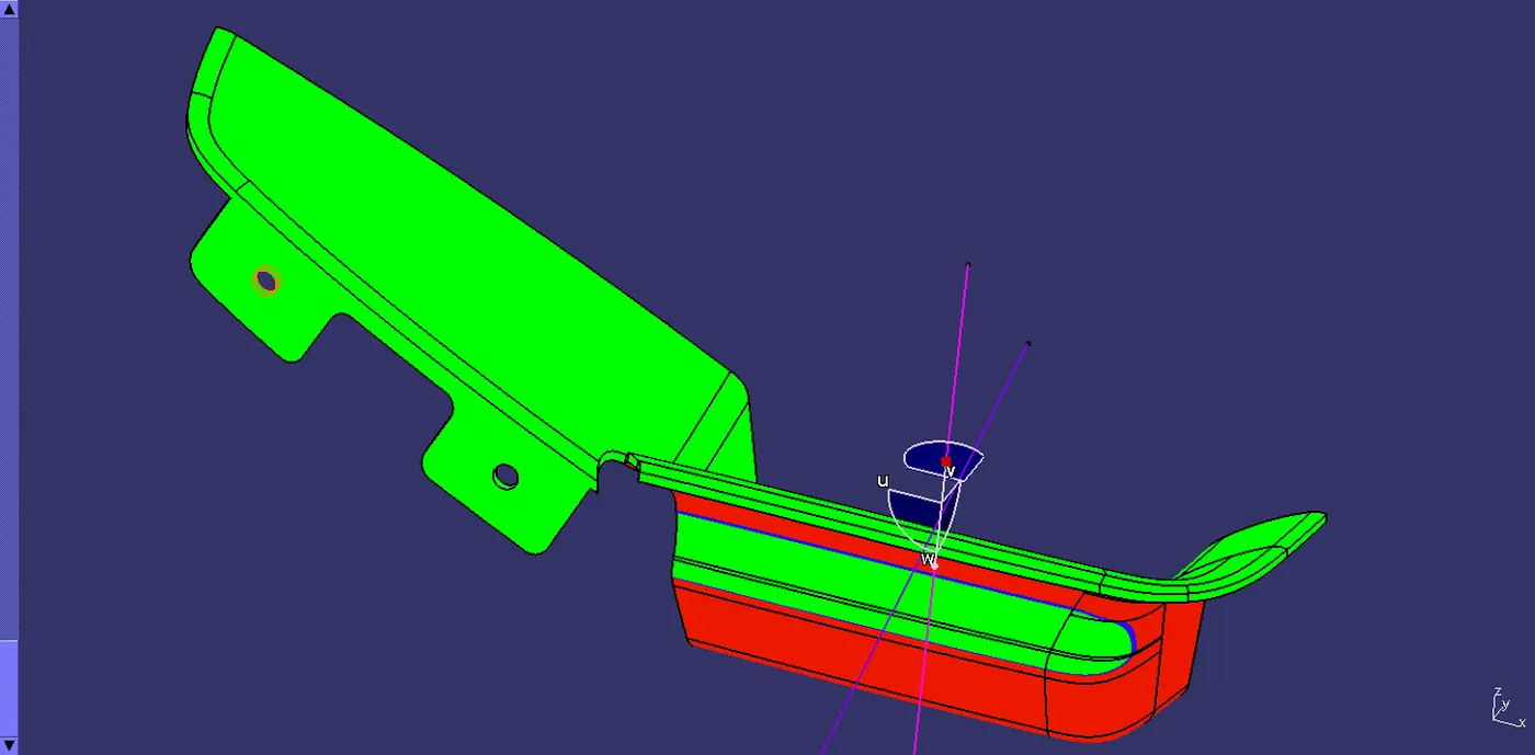
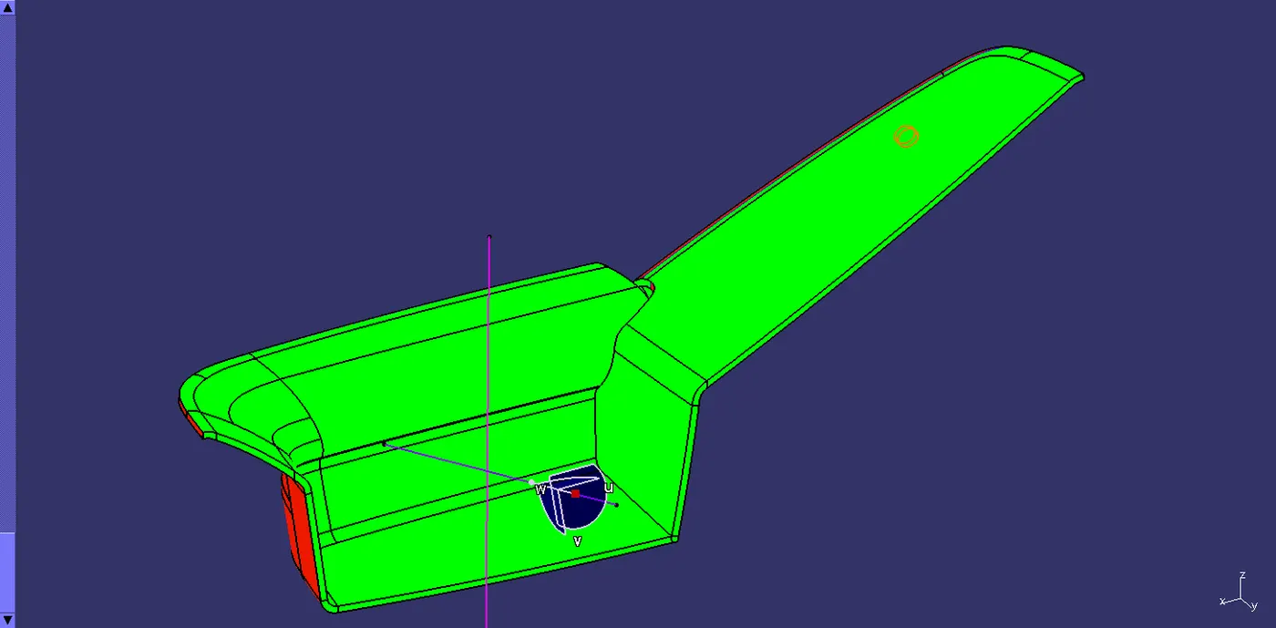
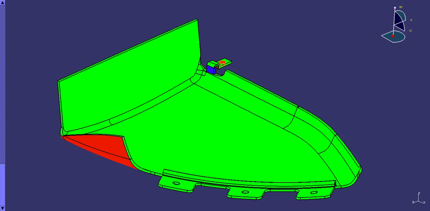
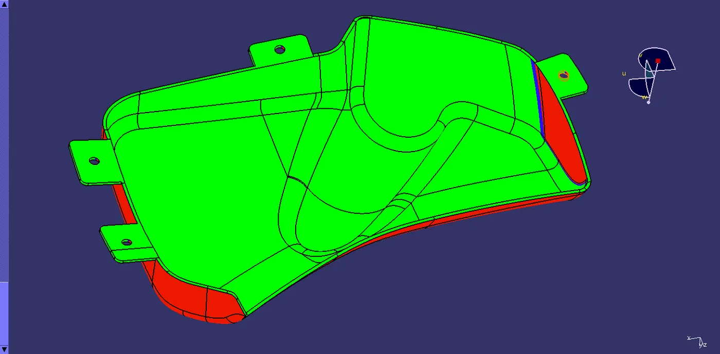
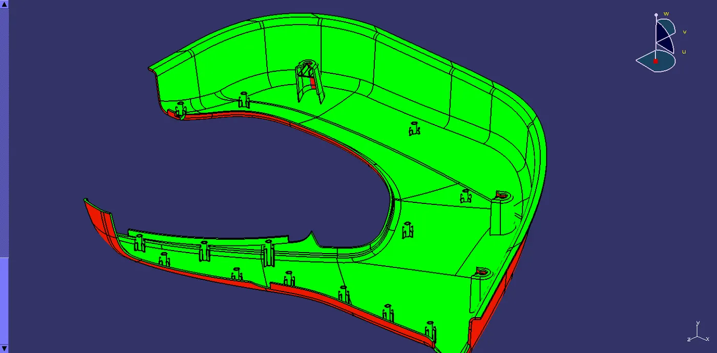
STEP 16: FINAL DRAFT ANALYSIS
Insert > Analysis > Feature Draft Analysis
Note: Ensure you have the Material view mode ON.
- Define the Draft direction using the "Compass" option.
- Drag the Axis system representation close to the model and align it along the tooling axis.
- "Lock" the Draft direction.
- Set the Colour scale
| Colour | Description | Value |
| Green | Core Side | Above 0.5 degrees |
| Blue | Parting Line | 0 degrees |
| Red | Cavity Side | Below 0 degrees |
- Place the Analysis Tool (Arrow Icon) anywhere on the model and review the colours on the feature.
- If any feature is showing Blue/Red then choose the same option again (It will switch to Analysis under Running point) and place it on the respective feature to review the deviation of the sweep angle from the Tooling Axis.
| PART NO. | INSTANCE NAME | DRAFT ANALYSIS: MAIN TOOLING | DRAFT ANALYSIS: SIDE TOOLING | ||
| 1 |
Straight Arm Rest |
 |
 |
||
| 2 |
Inclined Arm Rest |
 |
 |
||
| 3 |
Upper Map |
 |
|||
| 4 |
Lower Map Pocket |
 |
|||
| 5 |
Lower Substrate |
 |
RESULT
- The A surface of the following components converted to a solid body:
- Straight Arm Rest
- Inclined Arm Rest
- Upper Map
- Lower Map Pocket
- Lower Substrate
- Each component has a uniform thickness of 2.5mm.
- The components' surfaces (A, B & C) pass for Drafting analysis.
- The Plastic features follow the design guidelines and pass for the Lifter draft analysis.
- Clearance is provided on the Flanges, allowing for the Heatstakes to arrest and form an Assembly.
ARM REST
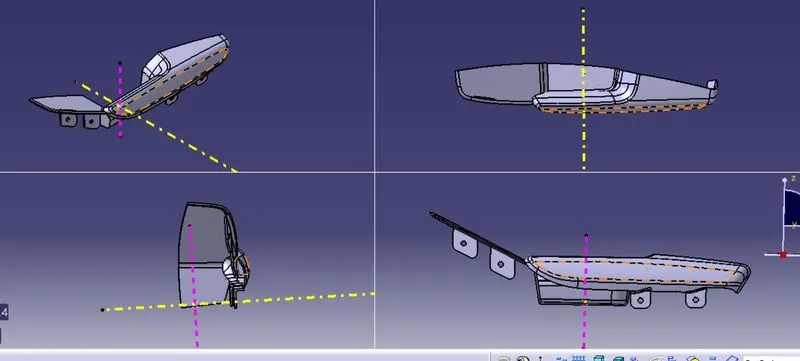
FEATURE TREE OF ARM REST-
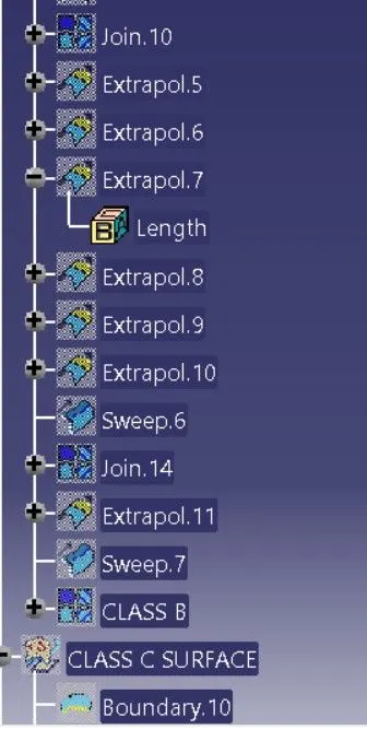
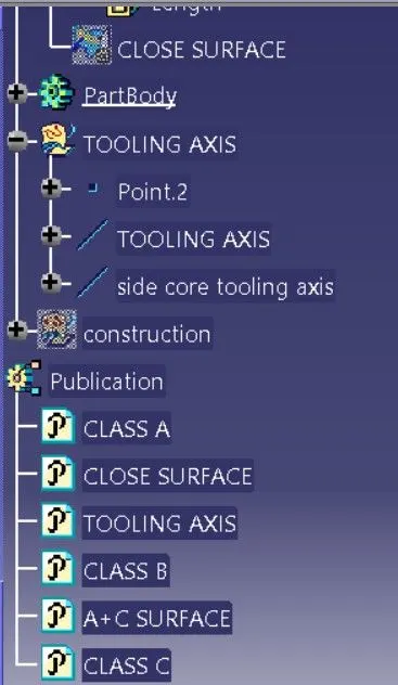
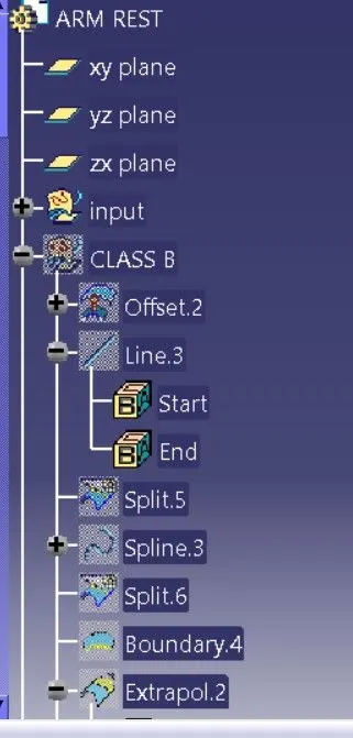
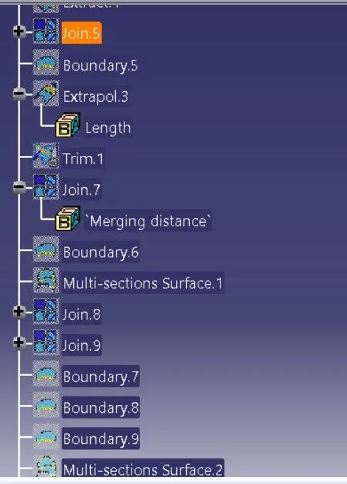
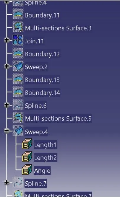
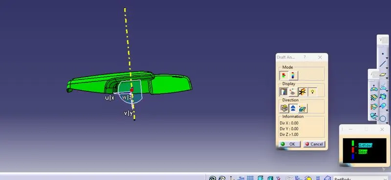
DRAFT ANALISISE-
BOTTLE HOLDER-
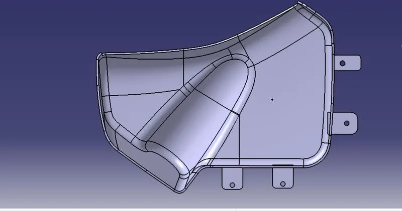
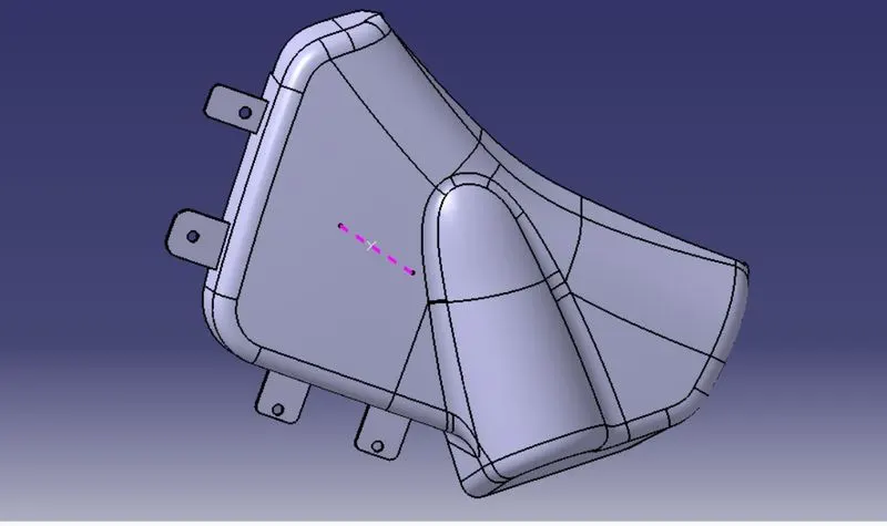
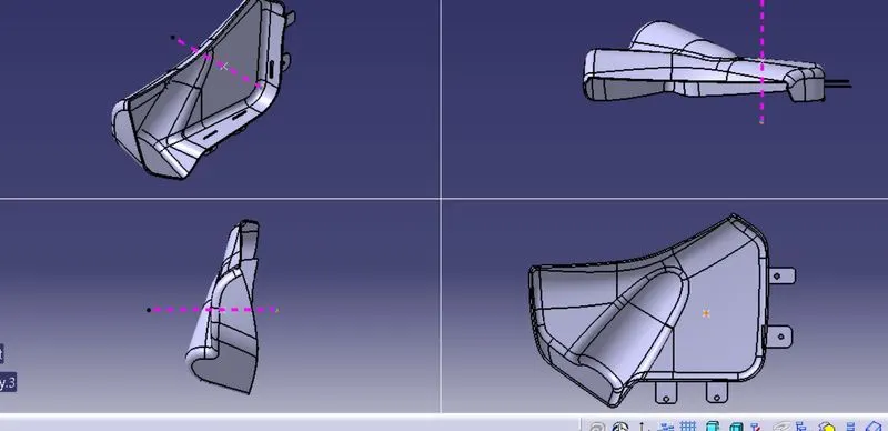
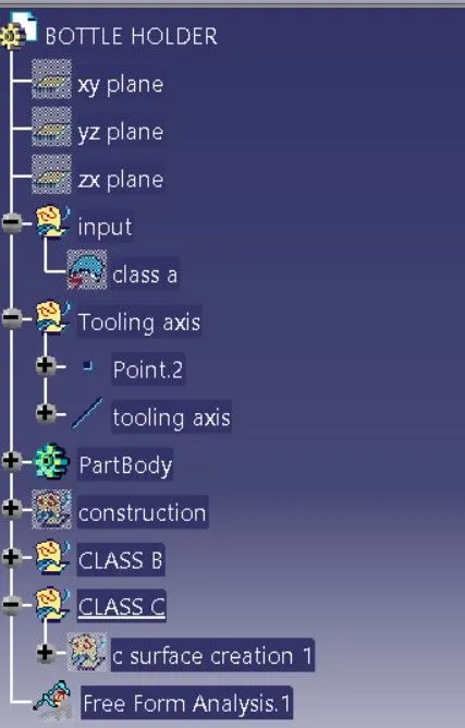
DRAFT ANALYSIS
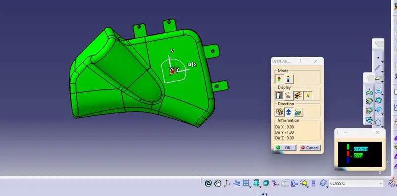
LOWER SUBSTATE-
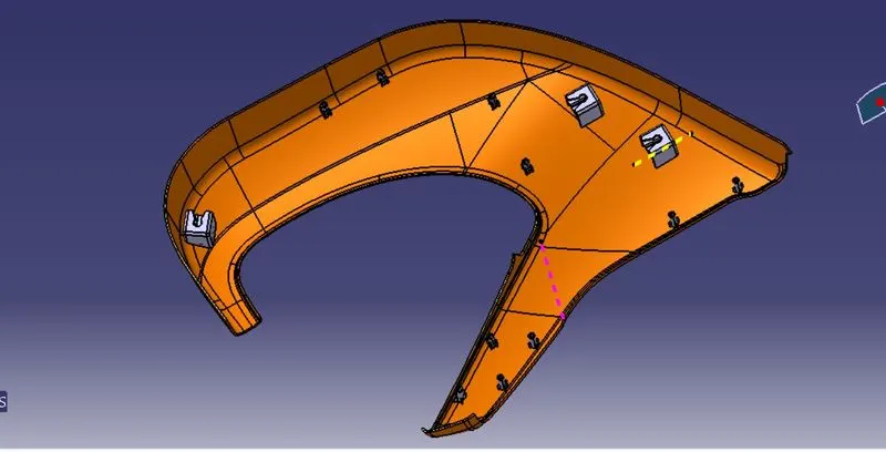
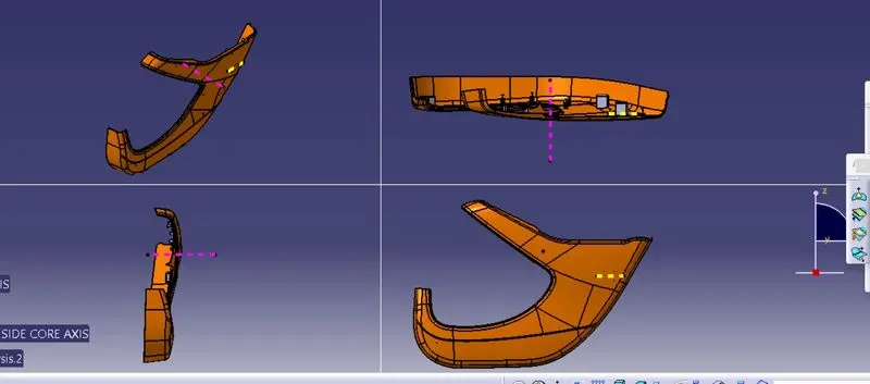
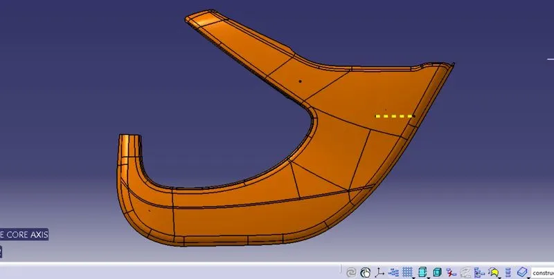
FEATURE TREE-
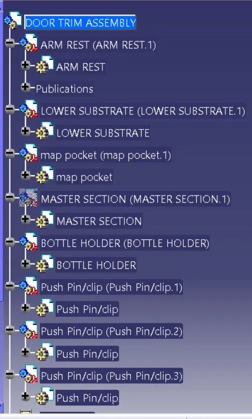
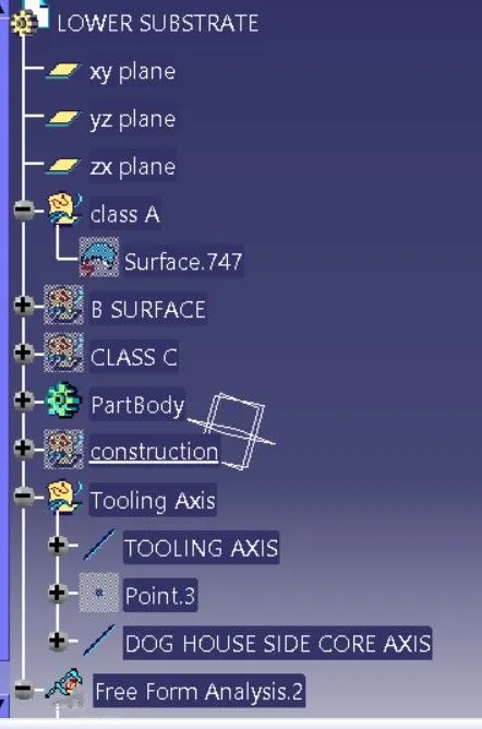
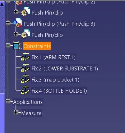
DRAFT ANALYSIS OF LOWER SUBSTATE-
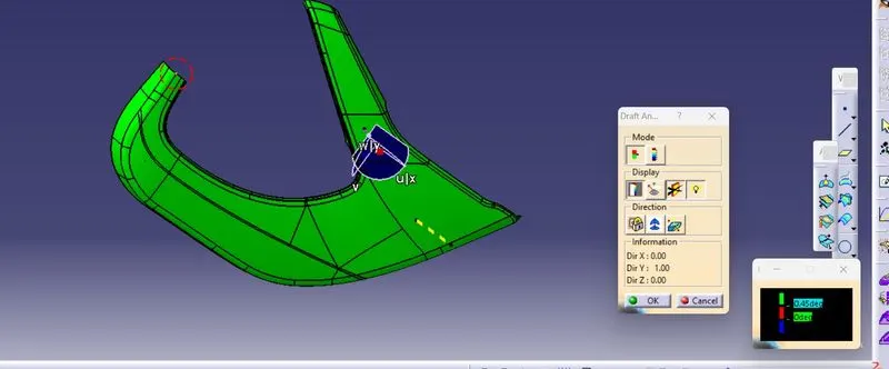
TOOLING AXIS OF DOOR TRIM ASSEMBLY-