Radar Mast & Final Assembly of Yacht
SUNNY_RADARMAST
- RADARMAST FEATURE TREE-
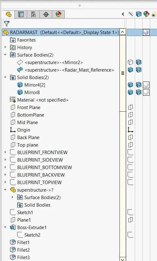
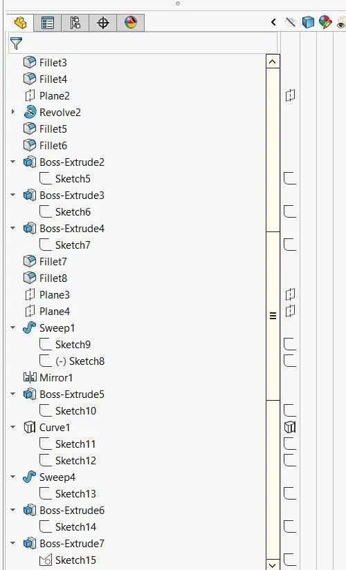
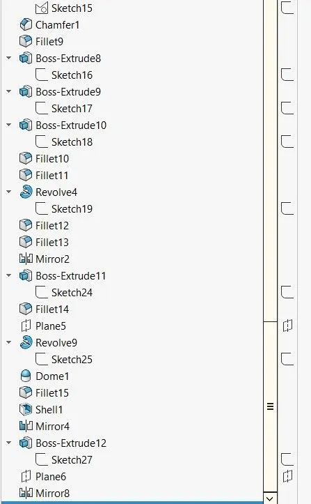
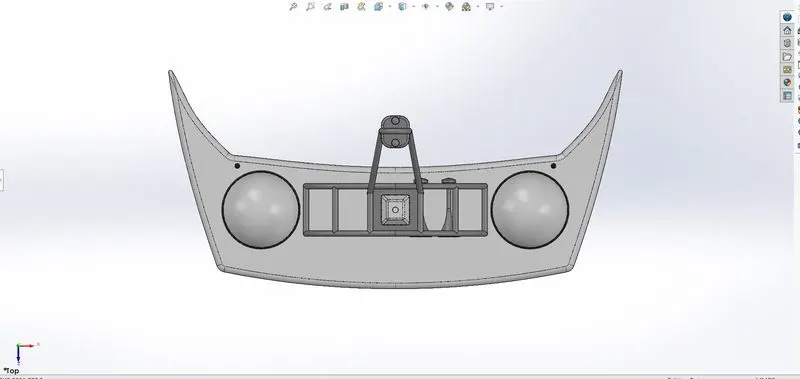
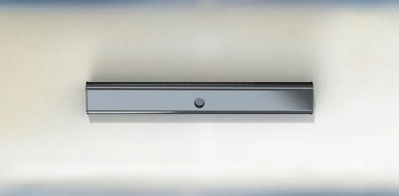
- TOP VIEW OF RADARMAST-
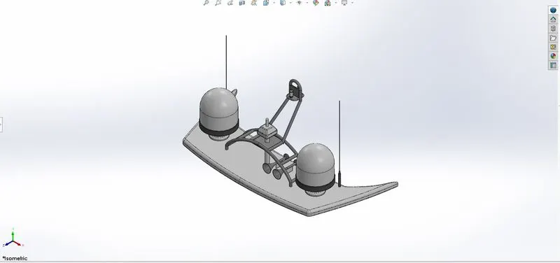
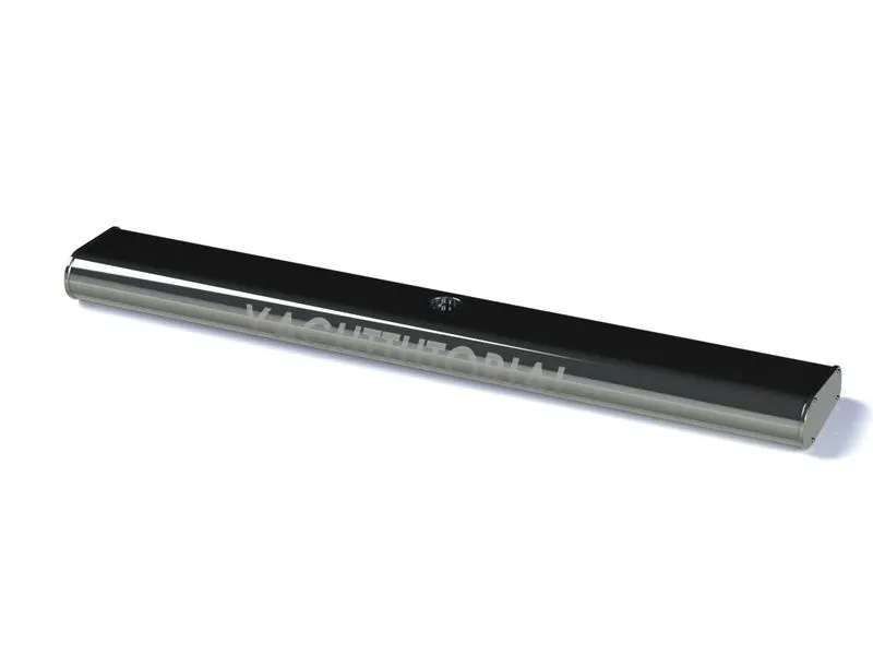
- ISOMETRIC VIEW OF RADARMAST-
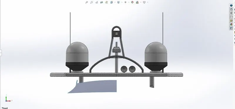
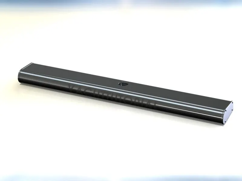
- FRONT VIEW OF RADARMAST-
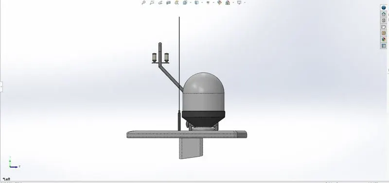
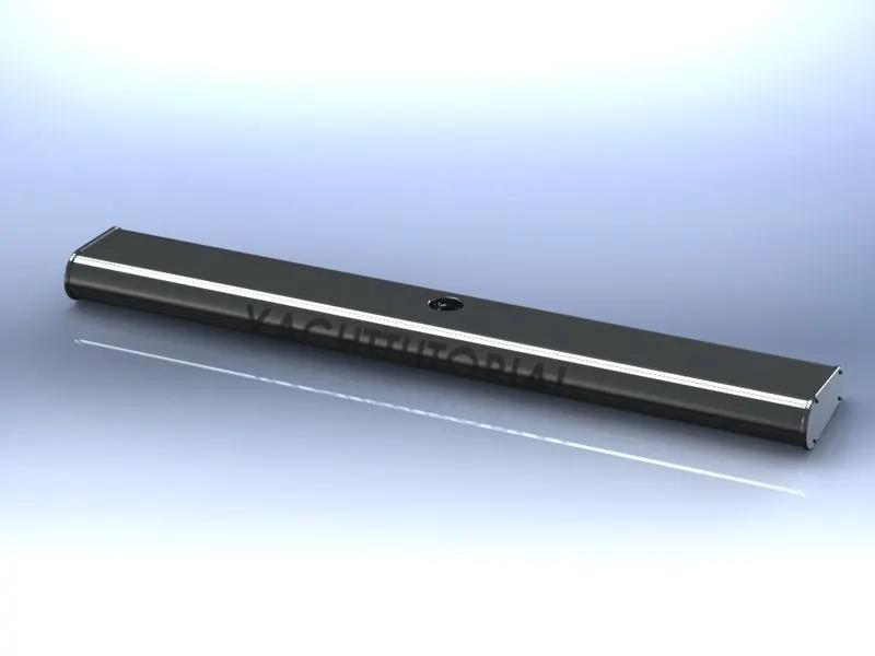
- LEFT SIDE VIEW OF RADARMA
SUNNY_YACHT ASSEMBLY
- TITLE OF PROJECT-MODELLING & ASSEMBLY OF SUNSEAKER PREDACTOR YACHT
- OBJECTIVES-
- in yacht assembly blueprint is most important .all indivisual parts of the yacht are design according to the blueprint
- in yacht all indivisual parts are design with fully define with the help solidworks commands.
- after designing of all indivisuals parts assemble them with the help of suitable constraints.
- give proper appearance of yacht after assembling of all indivisual parts.
- customize the appearance of all indivisuals parts and assemble yacht.
- rendering of yacht model by adding appearance,background scene,lighting,camera set up,& decals.
- SOFTWARE -solid works 2021 used
- INTRODUCTIONS-
- solidworks software is most important mechanical CAD software with the help of this software designer to show their skill & ideal of the part or model & assembly in realistic view in virtual representation.
- in the process of modelling a SUN SEAKER PREDATOR YACHT.we design a parts or model by using intial 2D sketches and then we turn them into 3D models by useing the tool like surface tools.
- Assembly contains parts or other assemblies called subassemblies.
- solidworks software design model quickly and precisely.these software are work very easily and smooth.
- photoview 360which help in rendering of final model & assembly to make more realistic after rendering.
- parts of yacht are modelled with the help of blue-print only.
- here almost part of the modell is modelled by using surface modelling and we make them into solid body by using surface knit commands.
- YACHT-yacht sailing used for pleasure,cruising or racing.to be termed a yacht as opposed to a boat.such a pleasure vessel is likely to be at least 33 feat (10m) in length.the commercial yacht code classified yacht 79 ft (24m) and over as large .yacht is basically DUTUCH words.
- DESIGN METHODOLOGY/APPROCH OF YACHT-
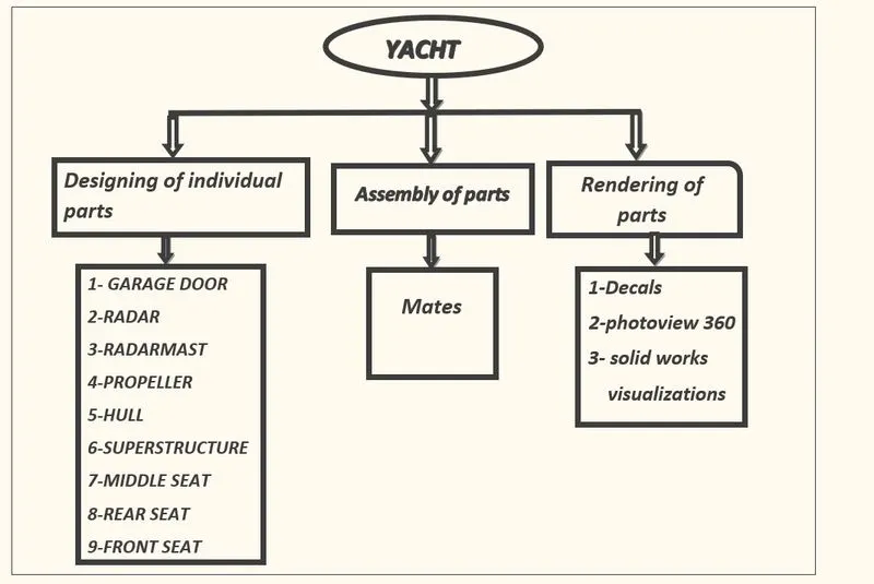
- DESIGN PROCESS-
- Blueprint set up
- Modelling of PROPELLER
- Modelling of RADAR
- Modelling of HULL
- Modelling of SUPERSTRUCTURE
- Modelling of RADARMAST
- Modelling of GARAGE-DOOR
- Modelling of REAR SEAT, FRONT SEAT &MIDDLE SEAT.
- Parts of YACHT-
- BLUEPRINT
- PROPELLER
- RADAR
- RADARMAST
- GARAGE-DOOR
- HULL
- SUPERSTRUCTURE
- MIDDLE SEAT
- REAR SEAT
- FRONT SEAT
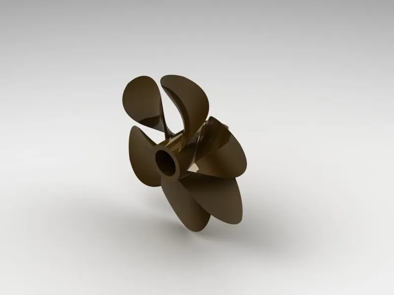
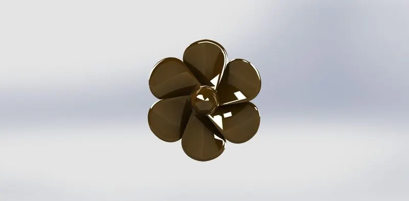
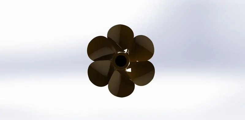
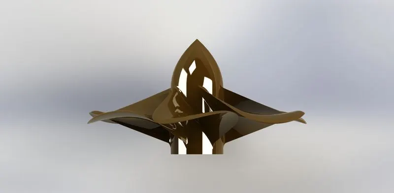
- PROPELLER-Propeller is very important part of the yacht without propeller yacht cannot move in water.the main function of propeller is to propel the yacht in forward direction.its works on the principles of Newton 3rd law of motion & bernoullis theoram.rotational motion of blades of propeller is converted into thrust by creating a pressure difference between the surface.A given mass of working fliuds is accelerated in one direction and craft move into opposite directions.
- COMMAND which are use in sketch-
- SPLINE
- CIRCLE
- LINE
- FEATURE USE IN PROPELLER
- EXTRUDE CUT
- REVOLVE BOSS/BASE
- LOFTED BOSS/BASE
- REFERENCE PLANE
- CIRCULAR PATTERN
- FILLET
- RADAR-Marine radarsare x band or s band radars on ships used to detect other shops and land obstacles to provide bearing and distance for collisions avidance and nevigations at sea. they are electronic nevigation instruments .that are used to rotating the anteanna to sweap narrow beam of microwaves around the water surface.surrounding the ship to the horizon ,detecting tangents by microwave reflected from them.
- COMMANDS ARE USE-
- LINE
- TEXT
- CIRCLE
- POINT
- PROJECTION
- IN FEATURE-
- EXTRUDE BOSS/BASE
- EXTRUDE CUT
- SKETCH PATTERN
- FILLET
- MIRROR
- SPLIT LINE
- HULL-A hull is the water fight body of yacht .the hull may open at the top or it may be fully or partially covered with deck.the line where the hull meets the water surface is called waterline.the hull of a yacht is a most notable structured entity of the yacht .to define the hull it can be said that it is the watertight encloser of the yacht.which protects the cargo machinery and accommodation spaces of the yacht from the weather,flooding and structural damage.the intermediate member of the hull consists girders ,webs &stringers.it is structural arrangement may be longitudinal.
- COMMANDS ARE USE IN SKETCH-
- LINE
- SPLINE
- CIRCLE
- RECTANGLE
- ARC
- SLOT
- 3D SKETCH
- SKETCH PICTURE
- FEATURE ARE USE IN SURFACE-
- EXTRUDE SURFACE
- REVOLVED SURFACE
- LOFTED SURFACE
- SURFACE TRIM
- SURFACE FILL
- SURFACE KNIT
- DELETED FACE
- PROJECT CURVE
- CHAMFER
- FILLET
- REFERENCE PLANE
- SPLIT
- SPLIT LINE
- EXTRUDE BOSS/BASE
- EXTRUDE CUT
- MIRROR
- GARAGE DOOR-A garage door is a large door on a garage that open either manually or by an electronic motor .garage door are frequently large enought to accommodate automobiles and other vehicles.some garage door slides or swing horizontally door made of wood ,metal and fibre glass.
- COMMANDS ARE USE IN GARAGE DOOR IN SKETCH-
- LINE
- SPLINE
- CIRCLE
- TEXT
- EXTRUDE CUT
- REFERENCE PLANE
- FILLET
- SHELL
- MIRROR
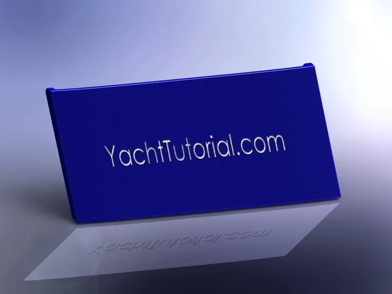
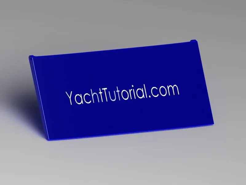
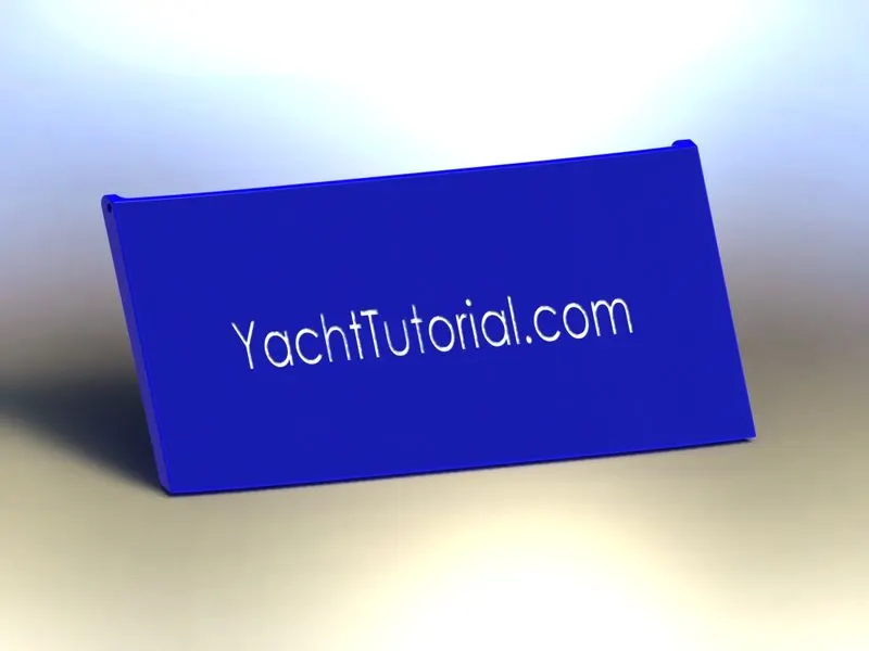
- FRONT SEAT-front seat feature two connected seat that are built back to back from one and other .lounge seats can also fully recline right back to make it easier for you to kick your feat up and get more comfortable.front seat in our model are places before the superstructure and also it has sun pads to rest on it .
- COMMANDS ARE USE -
- SKETCH
- SKETCH PICTURE
- LINE
- SPLINE
- CIRCLE
- ARC
- EXTRUDE SURFACE
- LOFTED SURFACE
- TRIM SURFACE'
- FILLED SURFACE
- KNIT SURFACE
- SWEEPT SURFACE
- REVOLVE SURFACE
- EXTRUDE CUT
- REVOLVE BOSS/BASE
- CHEMFER
- FILLET
- MIRROR
- DOME
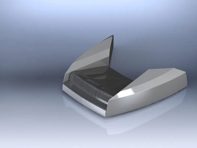
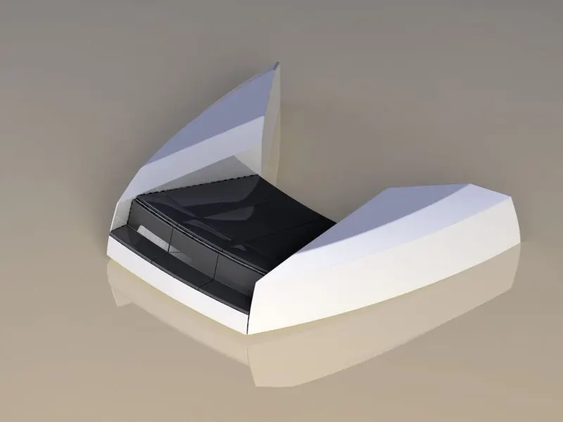
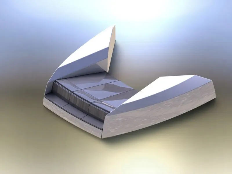
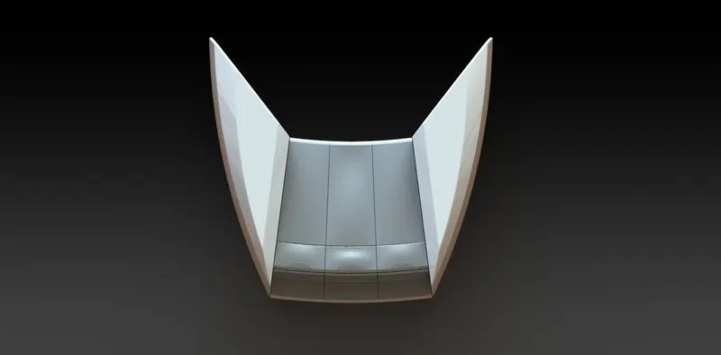
- MIDDLE SEAT-Middle seat in our model are placed just behind the superstructure.it is provide with a luxury table to dine out .it can be used to casual meeting.
- COMMAND ARE USED IN MODDLE SEAT-
- SKETCH PICTURE
- LINE
- RECTANGLES
- EXTRUDE BOSS/BASE
- CHEMFER
- MIRROR
- REFERENCE PLANE
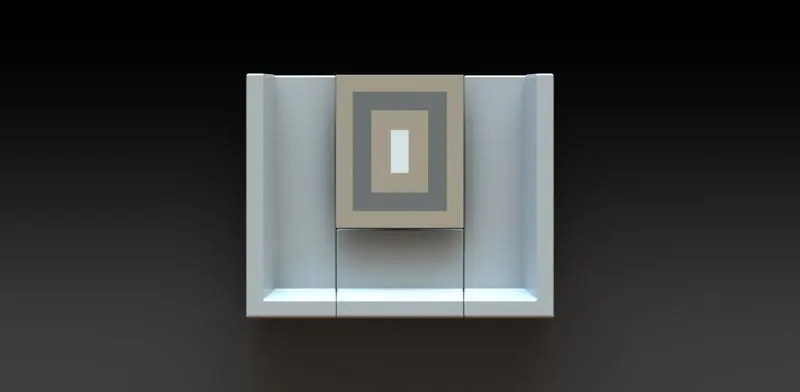
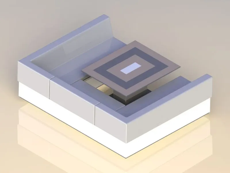
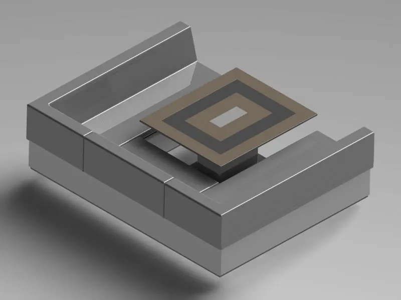
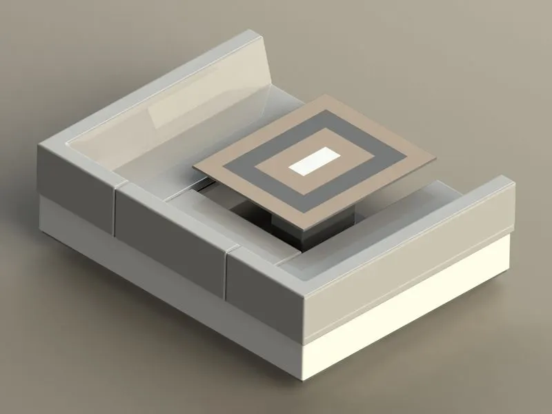
- REAR SEAT-Rear seat are placed at the end of the deck surface of hull .The rear seat consist of locker racks and steel door for our strairs. The flag is also placed behind the rear seat .
- COMMANDS ARE USE IN REAR SEAT-
- SKETCH PICTURE
- LINE
- SPLINE
- CIRCLE
- ARC
- RECTANGLES
- SWEEPT SURFACE
- EXTRUDE SURFACE
- LOFTED SURFACE
- KNIT SURFACE
- FILL SURFACE
- RULED SURFACE
- LOFTED SURFACE
- REFERENCE PLANE
- EXTRUDE BOSS/BASE
- REVOLVED BOSS/BASE
- FILLET
- MIRROR
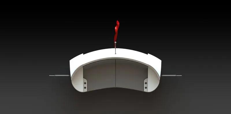
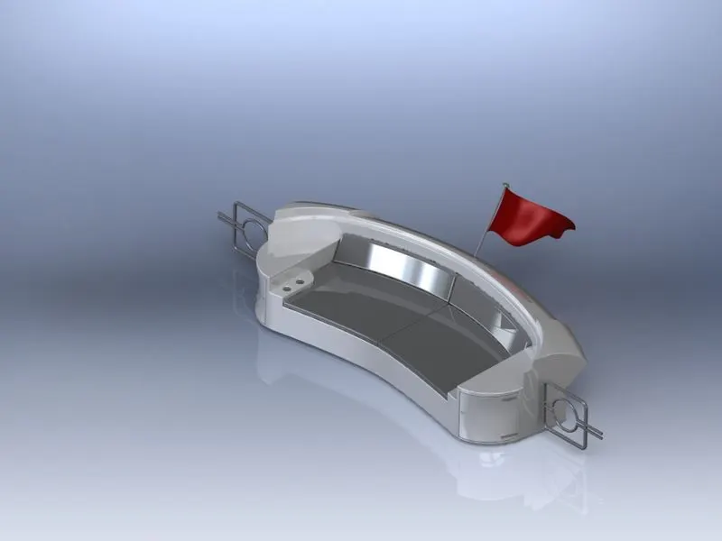
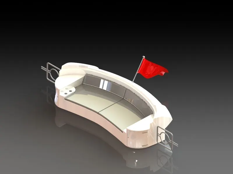
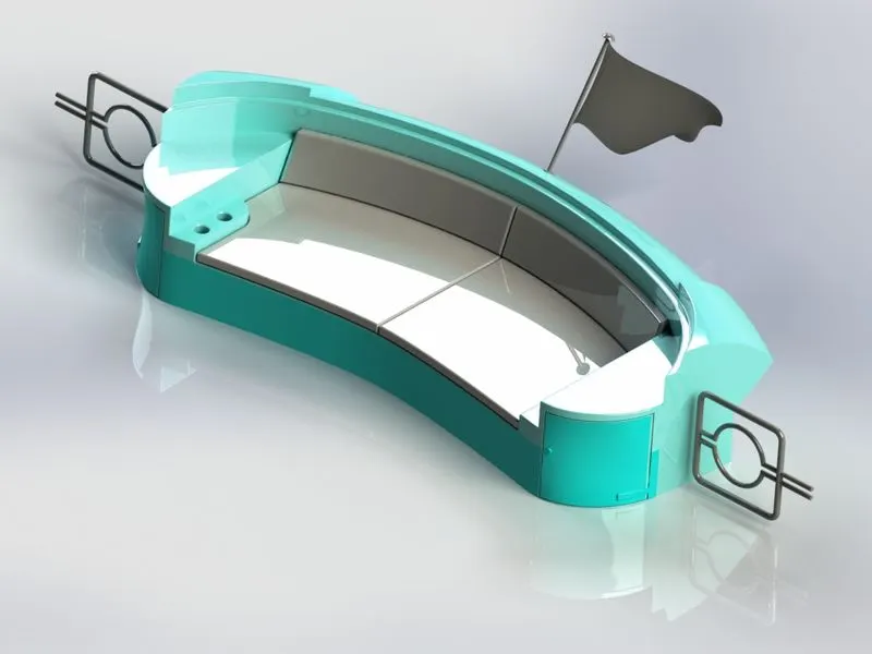
- RADARMAST-A Radarmast is a vertical ship structure mounted on the top of bridge and forward of the forecasting towards the shipbow .its accounts for supports plateform for the ships ,derrick and hold neccersary equipments such as RADARS nevigation light and ships horn. in the case of radarmast is used to hoist ships flage main job of the radarmasdt is hold the necessary equipment such as light ,ships horn,flages,and derricks in some case
- COMMANDS ARE USE-
- LINE
- SPLINE
- RECTANGLE
- ARC
- SKETCH PICTURE
- EXTRUDE BOSS/BASE
- LOFTED BOSS/BASE
- REVOLVE BOSS/BASE
- SWEEP BOSS/BASE
- REFERNCE PLANE
- PROJECTED CURVE
- FILLET
- MIRROR
- DOME
- SHELL
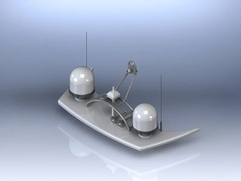
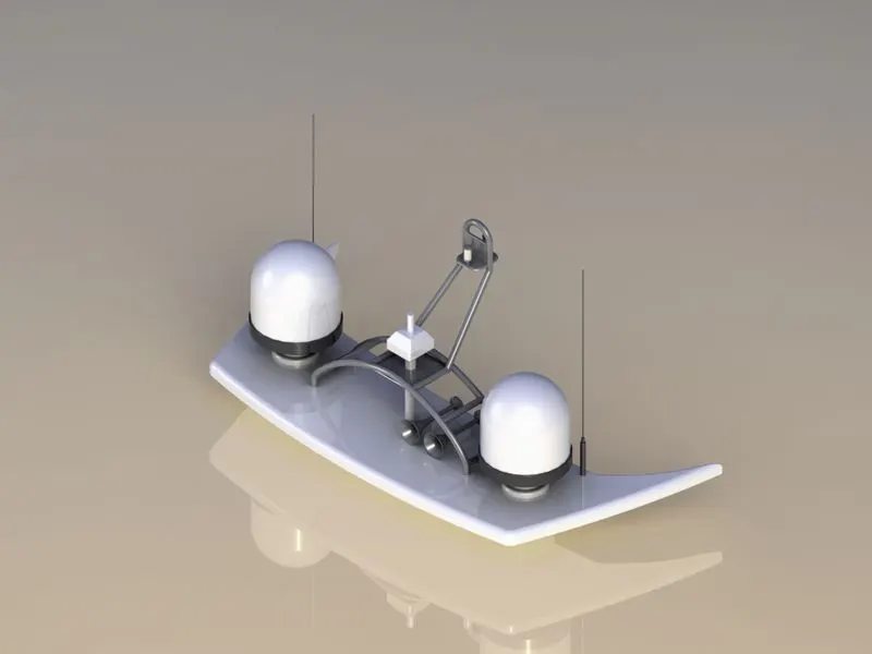
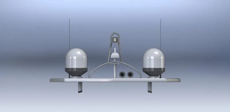
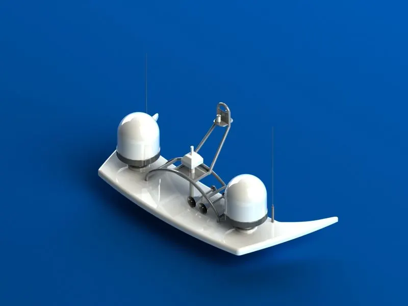
- SUPERSTRUCTURE-A superstructure is a upward extension of an existing structure above a baseline called ground level and it usually serves the purpose of the structure is intended use.a superstructure is decked structure on the freeboard deck.extending from side to side of the yacht
- COMMANDS ARE USE IN SUPERSTRUCTURE-
- LINE
- SPLINE
- CIRCLE
- RECTANGLE
- CENTER POINT ARC
- SKETCH PICTURE
- EXTRUDE SURFACE
- SWEEP SURFACE
- RULED SURFACE
- KNIT SURACE
- TRIM SURFACE
- EXTENDED SURFACE
- FILLED SURFACE
- LOFTED SURFACE
- REVOLVED SURFACE
- FILLET
- CHEMFER
- RROJECTED CURVE
- REFERENCE PLANE
- CONVERT ENTITIES
- SPLIT
- SPLIT LINE
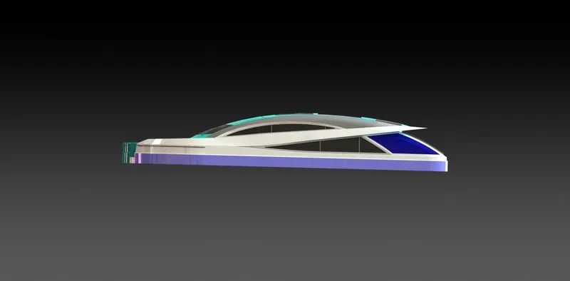
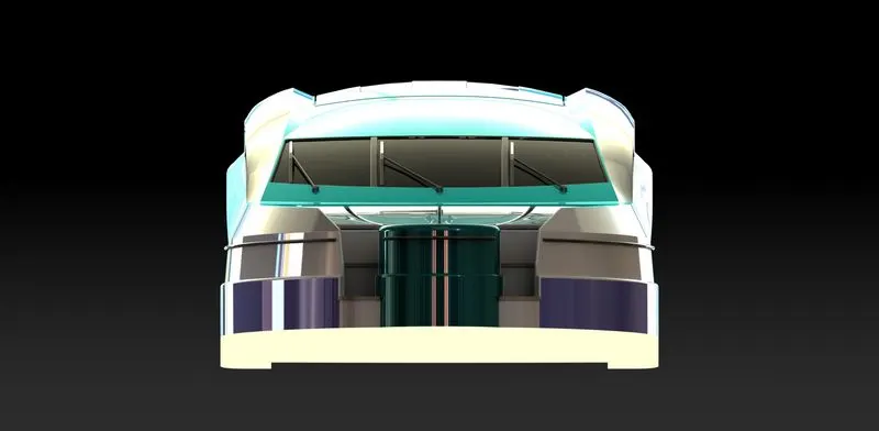
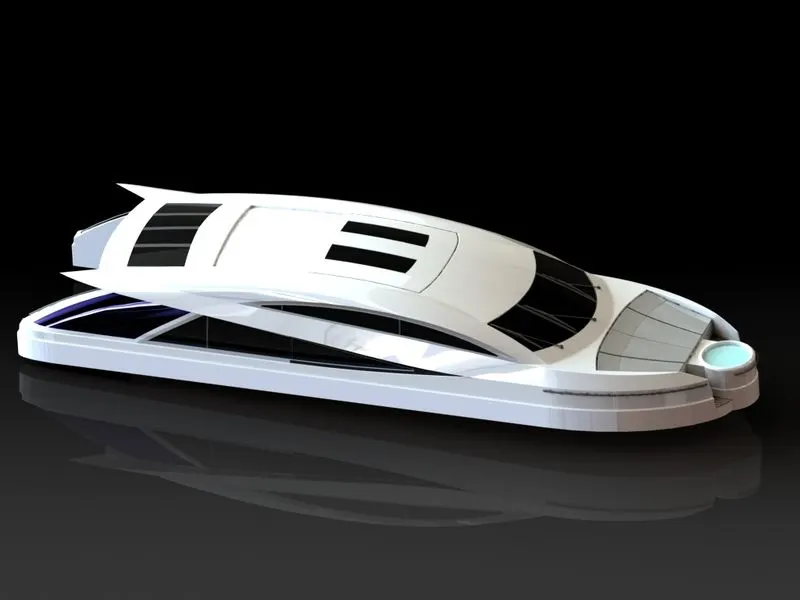
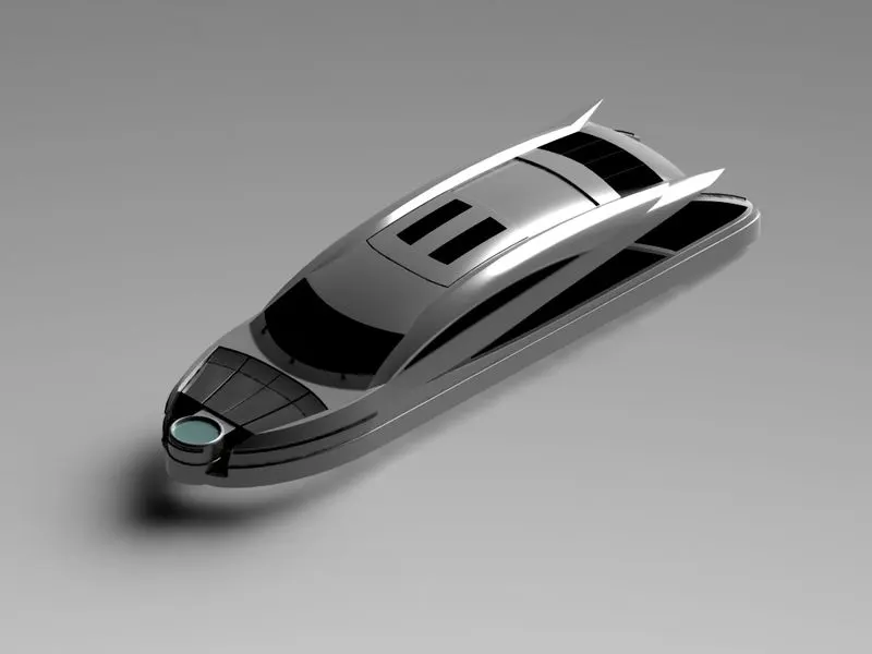
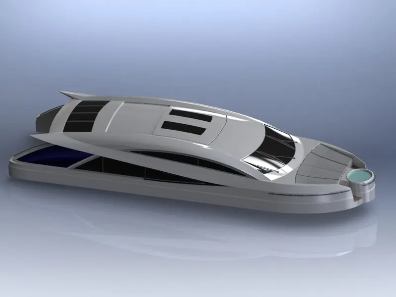
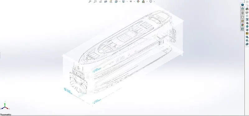
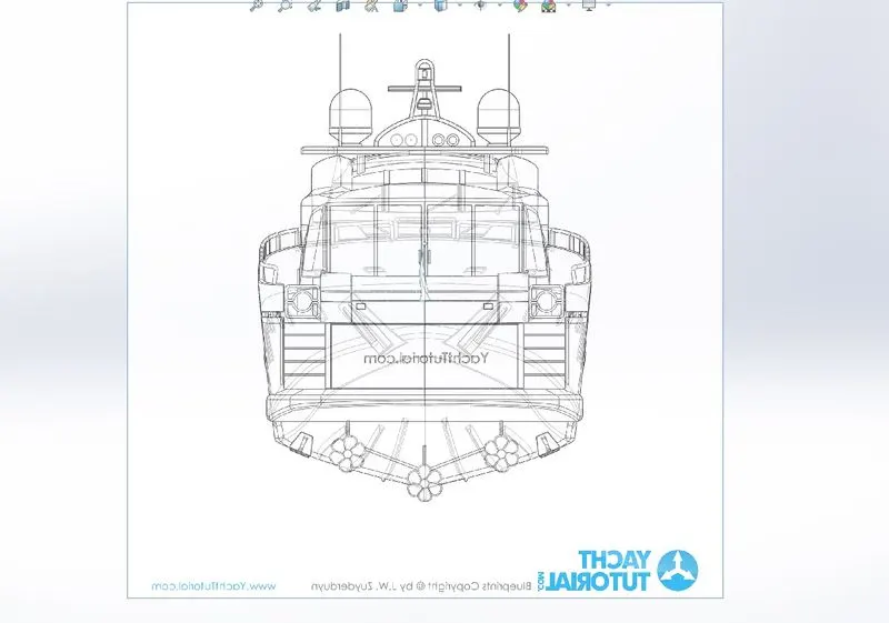
- BLUEPRINT-blueprint is basically design plane or techanical drawings of different orthographics views of a product. the main purpose of blueprint is to bring out the exact same shape and from of the product as designed by a designer. it is also the accuracy and the proportion of the product.designing a product without a blueprint may lead to multiple errors ,unnatural proportions and improper dimension.a proper blueprint setup omits all those problems. to set up a blueprint,we use sketch mode in solidworks in each part. in this case the image provided for the front view ,side view,top view,back view,are added in respective planes .one very important to note while setting up a blueprint is size of it .all the parts are going to be designed laying up the blueprint and taking its reference,it is very crucial to maintain the correct and real size of the blueprint in the very first step .it can either be adjusted manually with the dimensions or by the adjusting the scale bar.
- COMMANDS WHICH ARE USE IN YACHT & ITS PARTS-
- SKETCH-sketch is a 2D PROFILE .to create the sketch first we select plane and design the model by using the various commands as line,circle,spline etc.creating a model usually begins with a sketch from the sketch we can create feature. we can combine one or more features to make a parts then we can combine and mate the appropiates part to create an assembly from the parts or assemblies we can then create drawings.
- FEATURE-select the appropiate feature such as extrude and fillets ,determine the best features to apply and in what order to apply those feastures must be decide.
- face are a type of geometry that can be used to create solids feature.
- ASSEMBLY-select the components to mate and apply the mates.
- 3D SKETCH-when sketching in 3D we can snap to major direction x ,y & z respectively .those are constraints to the global co-ordinates system.when we sketching an a plane we can snap to the horizontal vertical directions in the plane and constrsaints are apllied to the horizontal and the vertical .these are constraints to a plane ,planer face etc.
- SKETCH COMMANDS ARE -
- SMART DIMENSIONS-create a dimensions for a selected sketch entity.
- LINE-line is one of the first sketching tools in the solidworks sketch commands manager ,which can be drawn horizentally ,vertically or at any angle . it play very important role to complete the 2D drawing of the products or part and very easy to utilised its features.
- CIRCLE-the circle is another important sketching tool which enables to create the circular drawings on the graphics area.these are two circle tools are available and they are centre circle and another one is perimeter circle.
- RECTANGLE -sketch rectangles' or square with a centre point at a selected angle.
- SPLINE-a 2 or 3 dimensions curve defines by the set of control points.
- SKETCH FILLET-A tangent arc in between two sketch entities can be create.
- OFFESET ENTITIES-copy a sketch entity to a specified distance from original entity must have a sketch entity already drawn and selected to use these tool.
- SKETCH PLANE-in setan image file into the back ground of a sketch .this allows the use to 2D sketches based off of the image.
- CONVERT ENTITY-convert entities enables to copy model edges into the your active sketch . these sketch elements are automatically fully define and constrained with an on edge relations .convert entity is like of set entity expect that the offset distance is always zero.
- FEATURE-
- EXTRUDE BOSS/BASE-one of the oldest commsands in the solidworks software is the extrude boss/base command.An extrude boss/base feature will allows use to make a 2D sketch and add thickness to it in the third dimensions.
- EXTRUDE CUT-extrude cut commands is use to remove materials by projecting a sketching normal to the sketching plane
- SPLIT-lines are used to divided model faces into two .split lines are created like any other sketched feature .they can be one or more connected sketch entities.
- DOME-this command are use to give some convex shape to selected surface.
- PIERCE-the pierce relation ship is used in sweeps .it can be through of as a 3D coincident relationship.
- PROJECTED CURVE-This command are used as a 3D curve on the profile. this curve can be achieved by two different line or spline. which starts from some directions and ends in the same directions with two difference.
- COMPOSITE CURVE-it can create by combining curves ,sketch geometry & model edges into a single curve .composite curve can be used as guide curve when creating a loft or a sweep.
- FILLET-fillet are used to create a smooth curve on the profile or at the edge for this constant size ,fillet is used.
- CIRCULAR PATTERN-this feature one selected of face as required and selection of equal spacing with required angle and no of instances.
- REVOLVE BOSS/BASE-this feature helps to revolve the open sketch as well as closed sketch with the help of one axises.
- SKETCH PATTERN- in this feature selection of the face is required to create multiple faces by selecting 2D sketches.
- MIRROR-it is used with midplane or mid line through which it is similarlly and symmetrical with the original body which is mirror.
- SURFACE MODELLING-surface modelling is a method of creating plane or non planer complex geometry.which has zero thickness.zero thickness geometry is known as surface.the surface are generally used to create model of complex shapes.we can convert the surface model in solid models.we can also extruct a surface from solids model by using the tool available for surface modelling.
- ADVANTAGE-
- surface give much more flexibility when creating complex shapes that cannot be done using solid features
- surfaces can be used to build a shapes face by face rather than all at one.
- surface can be used as refernce geometry
- surfaces can be more efficient than solids features depending on objects.
- SURFACE COMMAND-
- LOFT SURFACE-this cannot be create any solid body ,it creats only zero thickness profile by selecting line or spline as profile and guide curve.
- SURFACE TRIM-This command are used as to trim the surface where surface intesect with another surfaces a plane or a sketch.
- KNIT SURFACE-This command are used to combine two or more adjecent ,non intersecting surfaces into a single surface body.this surfaces must joint at an edge .if the resulting knit surface encloses a volume .we can create a solid body from the property manager.
- MOVE/COPY SURFACE-Move o copy surfaces about plane or a sketch.
- OFFESET SURFACE-Offeset surfaces using one or more contigeous faces .this tool helps us to create an offeset surface with gaps.
- EXTEND SURFACE-This command are use to extend one or more edges or faces on asurfaces based on end conditions and extension type.
- MIRROR SURFACES-A mirror features is a copy of a selected feature .mirrored about a plane or planer faces .a mirror sketch entity is a copy of a selected sketch entity that is mirrored about a centerline after original features or sketch is modified.the mirrored copy is updated to reflect the change.
- SHELL-shell is used to create a hallow profile by selecting the face or body with require thickness.
- SURFACE FILL-This command are use to fill the surface .this command are similar to surface loft
- SURFACE SWEEP-Surface sweep is same sweep boss/base but in surface modelling surface sweep is used by selecting profile and part for the sweep.
- RULED SURFACE-Ruled surfaces creates a tapered curve surface with the help of a single edge with a specified surface.
- REVOLVED SURFACE-Revolved a sketch or sketch contours around an axis to create a surface features.
- SPLIT POINT-We can split a sketch entity to create two sketch entity.
- ASSEMBLY-The assembly of YACHT is very simple.we have take the base deck surfaces for the most of the parts it gets mates autometically although some mates are used to assemble the yacht.
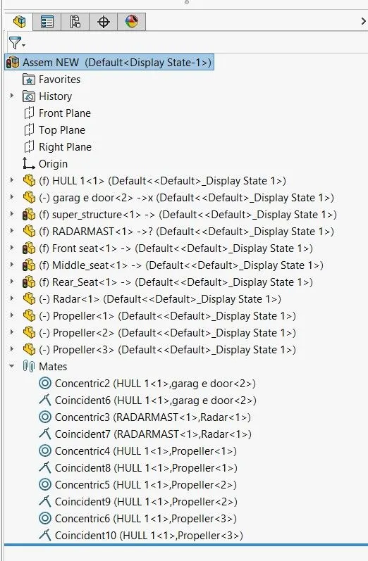
- ASSEMBLY PROCEDURE-Import the all parts manually by using inset component option.then fix the hull & its all parts by applying the coincident mate to the top ,right ,front planes of the assembly and hullrespectively.then each parts apply neccessary mates required by the blueprint using coincident mates ,angle mates,distances mates etc.
- FEATURE TREE OF YACHT-
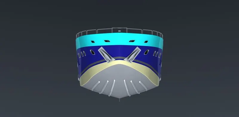
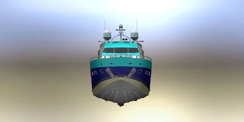
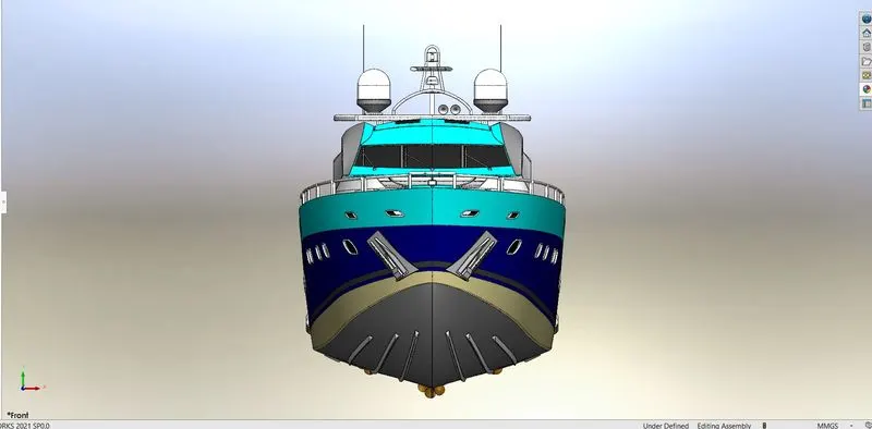
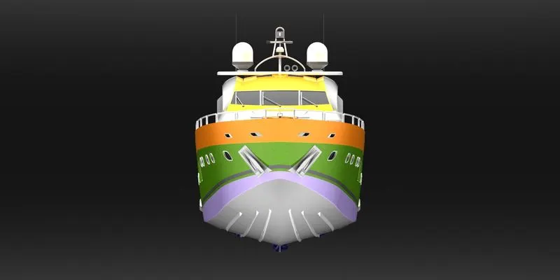
- FRONT VIEW OF YACHT-
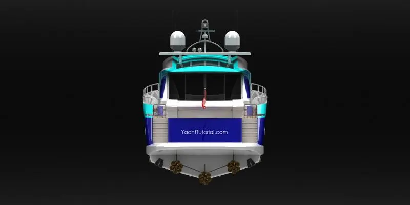
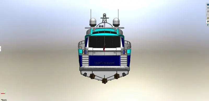
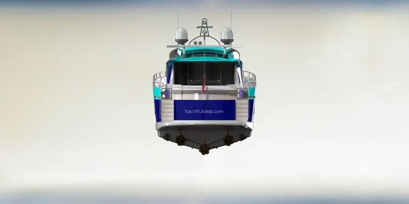
- BACK VIEW OF YACHT-
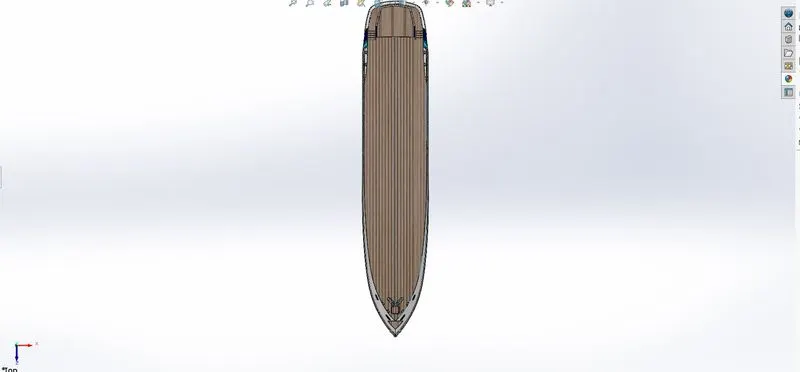
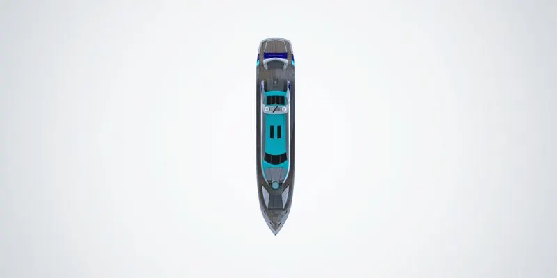
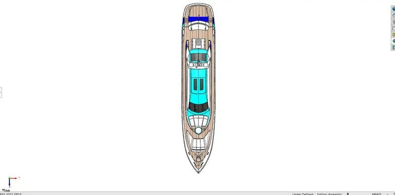
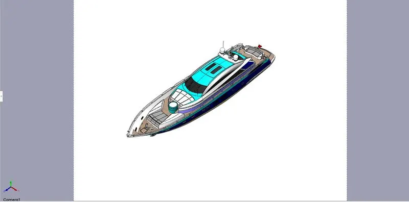
- TOP VIEW OF YACHT-
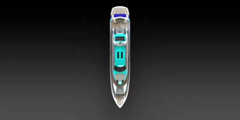
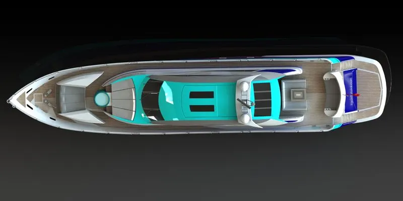
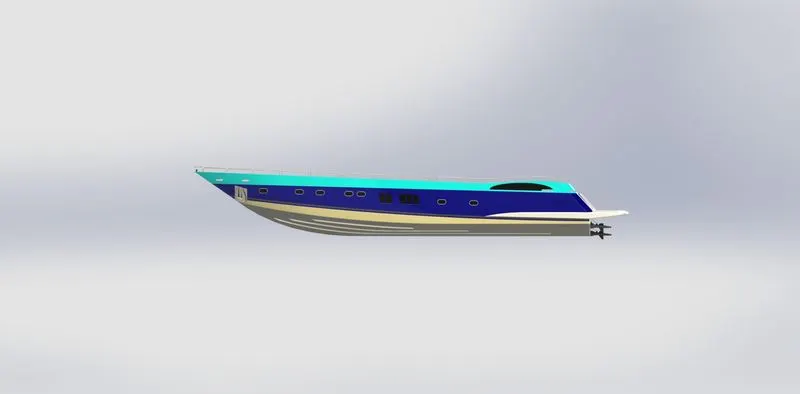
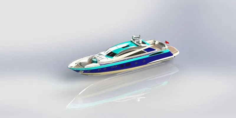
- SIDE LEFT & RIGHT VIEW OF YACHT-
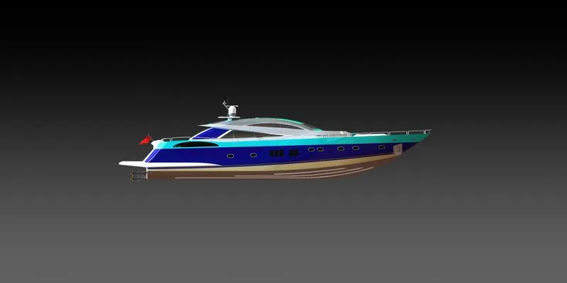
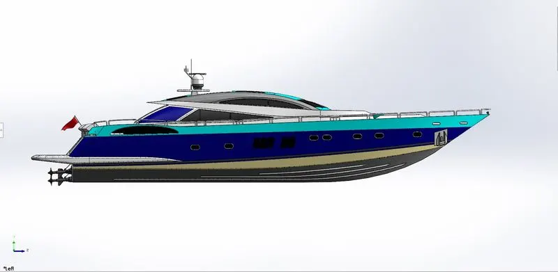
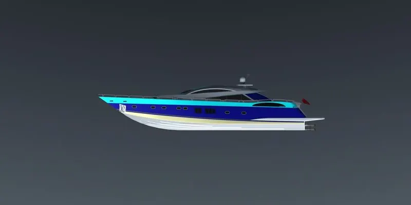
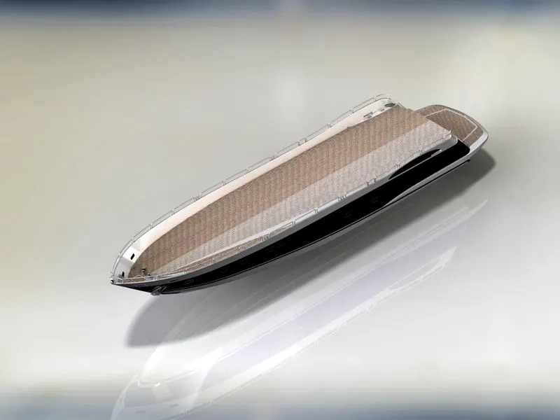
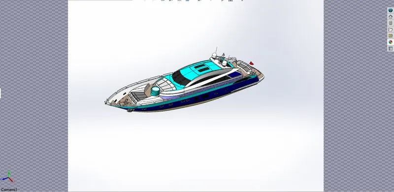
- ISOMETRIC VIEW OF YACHT-
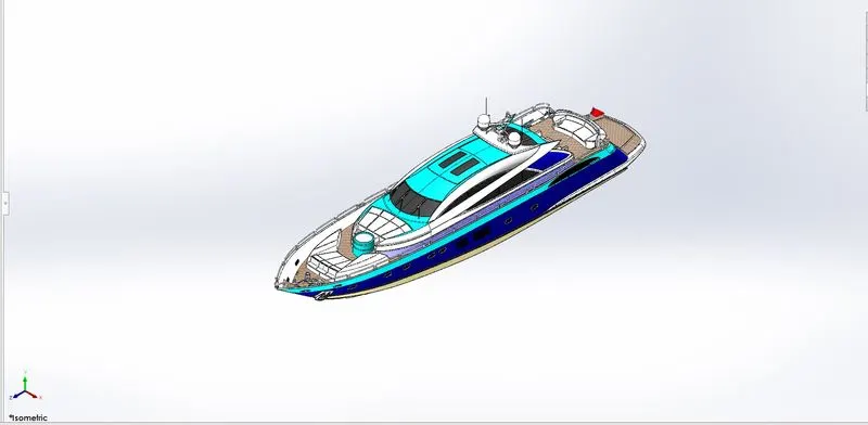
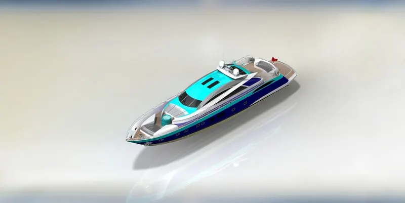
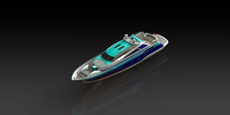
- CAMERA VIEW OF YACHT-
- MATES-A mates is a geometric relation ship such as coincident ,perpendiculer,tangent and so on between parts in an assembly.
- MATES ARE-
- COINCIDENT MATE
- CONCETRIC MATE
- DISTANCE MATE
- INSERT COMPONENT-We can insert multiple instances of the group of components without closing the property manager.
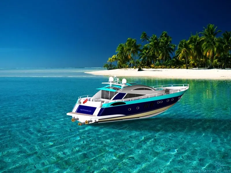
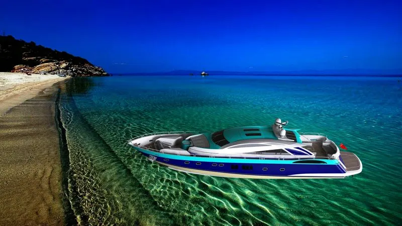
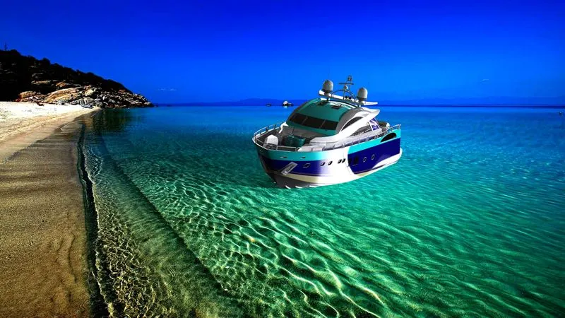
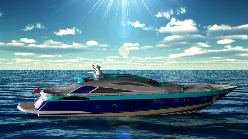
- RENDERING-Rendering is most important setion of design to make the design to more realistic.there are done two ways
- PHOTOVIEW 360
- VISUALIZATION
- PHOTOVIEW 360-PHOTOVIEW 360 is distinguished from real view in that it is not a process of the gpu and photo realistic renderings can be achieved regardless of the graphics card used photoview 360rendering are more photorealistics than real view because lights rays and reflection are more accurately calculated.
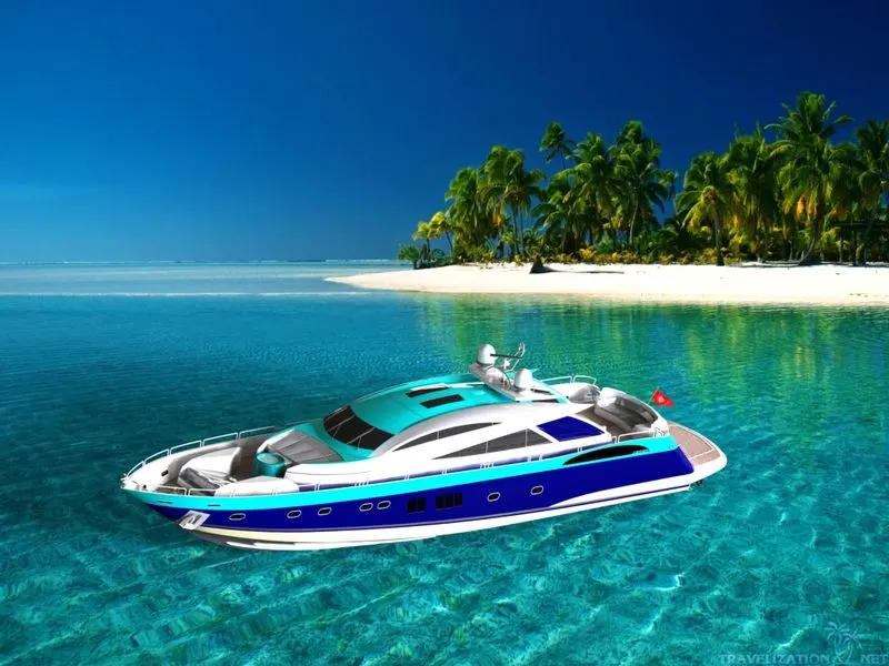
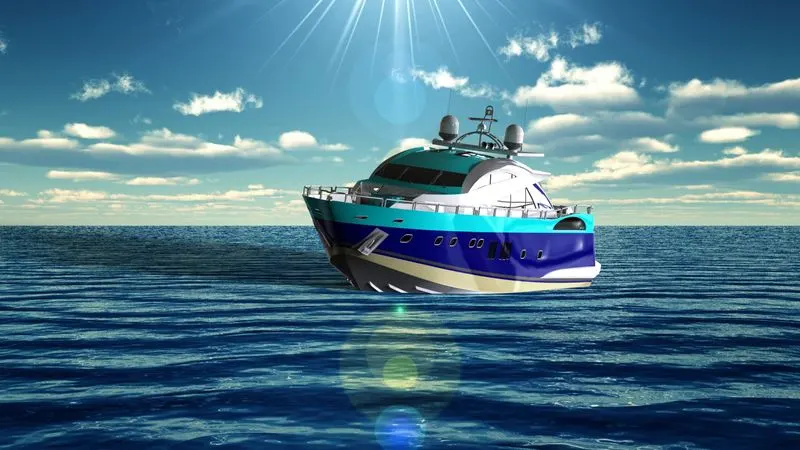
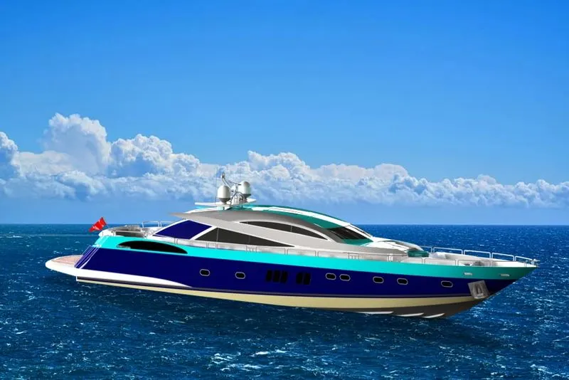
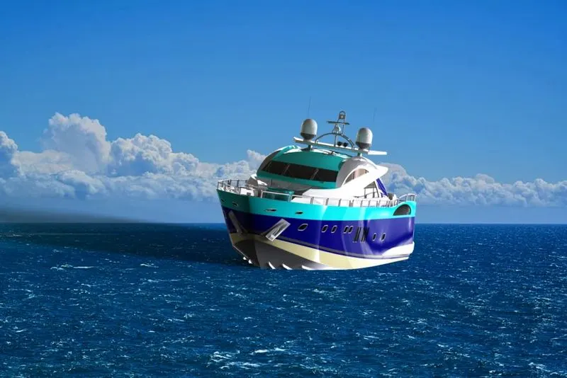
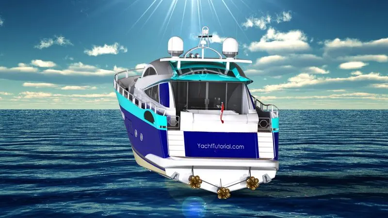
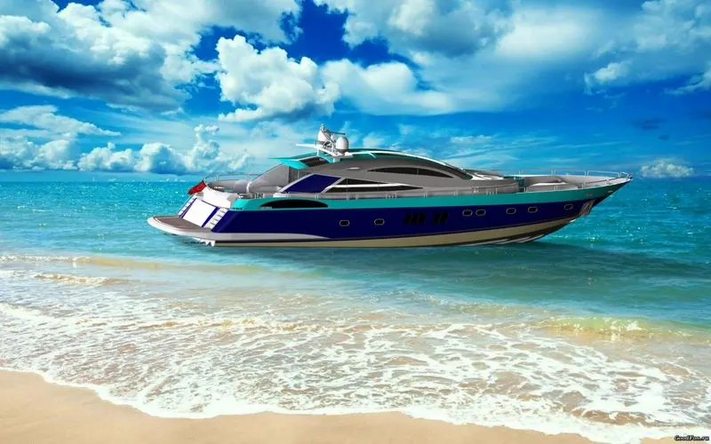
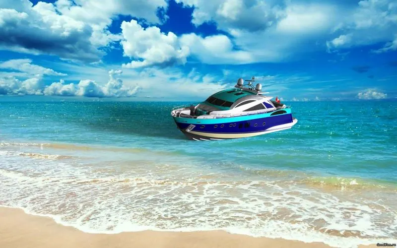
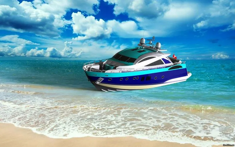
- photoview 360 rendering supports-
- SELF REFLECTION
- HDRI LIGHTING
- APPEARANCE-Appearances control the way surfaces of the model look.they can be applied at the part body assembly feature or face of the model.all surface of the model have been an appearance applied to them.
- PHOTOREALISTIC RENDERING-PHOTOREALISTIC rendering is the process of photographics expect we are useing a computer model instead of physical model.
- PHOTOVIEW 360 SOFTWARE-photoview 360software are fully intrgrated into the solidworks.solidworks create photorealistic images directly from solidsworks models.rendering may be created from photoview 360software.parts and assemblies .but not drawings
- some important feature of photoview 360software are-
- photorealistic image directly from solidworks models
- photoview 360 interacts with the 3D geometry create with the solidworks .models are accurately represented in the photoview 360.
- fully intergrated into solidsworks.
- APPEARANCES IN PHOTOVIEW 360-Appearances affect the ways a surfaces reacts to light s may be applied to parts feature or faces appearances are two type
- PROCEDURAL
- TEXTURE
- PROCEDURAL-it consist one or more colours and the way the appearances reacts to light
- TEXTURE-texture appearances are applied like wallpaper .during application they can be streched ,strunk,rotates & reoriented to make them it the surface.
- SOLIDWORKS VISUALIZATIONS FEATURES ARE-
- Demonstrate product are more effectively with full animations of parts ,models
- import out solidworks CAD motion studies for trully photographics animations
- Quickly show off the final design with one click 360 degree spines
- Create interactive web content such as interior panorames and exterior rps
- CONCLUSIONS-
- How to design a part or a model with proper 2D sketching and dimensioning.
- How to make a fully define sketch
- How to model a part or component using different features like surfaces modelling and solid modelling etc.
- How to make an assembly by using proper mates.
- How to make photorealistics view of a model by using photoview 360 and solidworks visualisations.
THANKS
NOTE-I have apply decal but due my software problem after editing decal will show.