Project 1
ENGINE HARNESS
https://drive.google.com/file/d/176J_HFrsD4HK05voe5CXaVNsXd1RFSO0/view?usp=sharing
OBJECTIVE : The objective of this project is to route the wiring harness on given Engine and prepare flatten view drawing in CATIA V5. All types of packaging rules have to be considered while routing the harness. Also, Industry best practices should be demonstrated in design. All the necessary details like clearance, clipping/clamping selection, harness fixing requirements, harness continuity should be provided in order to design wiring harness.
INTRODUCTION :
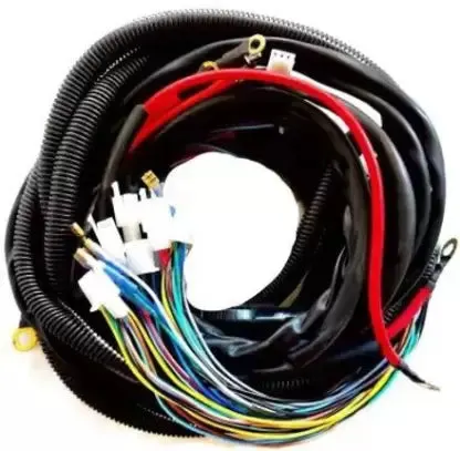
A wire harness, also commonly referred to as a wiring harness, is an exterior sheath used to cover some types of electronic wires. Generally, wiring harnesses are made of thermoplastic or thermoset materials that can help protect the cables from the environment.
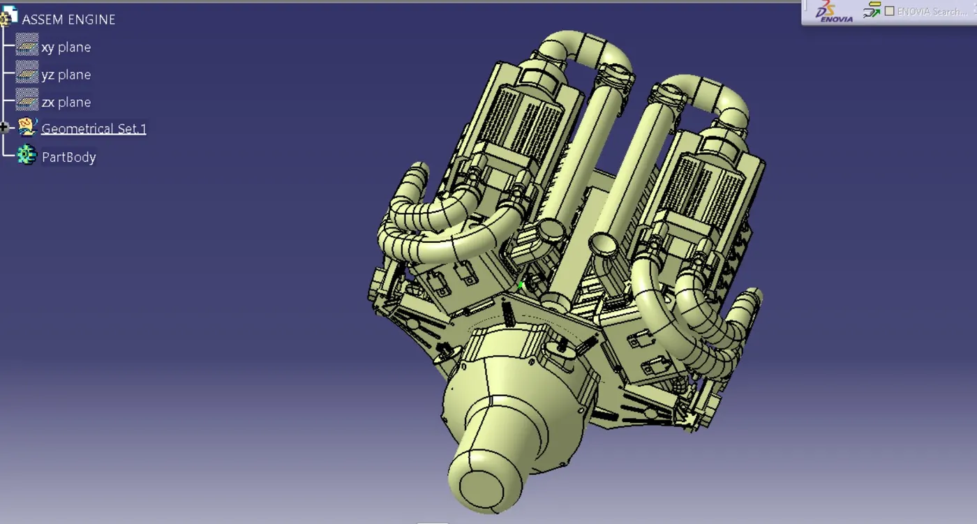
- The below figure shows the 16 valve Bugatti Engine where 8 cylinders are placed on the right side and 8 cylinders are placed on the left side.
- There are total 16 injectors where 8 injectors are used for 8 cylinders on right side and 8 injectors are used for another 8 cylinders on left side.
- Also there are 4 cam-shaft sensors, so there are total 20 sensors that we have to connected electrically.
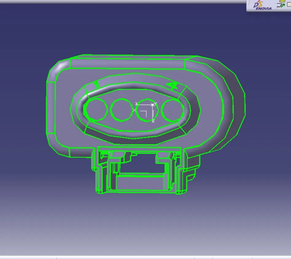
- Generally, 4-pole connectors are used for f
- uel injectors of the engine.
- The engine will also have an interconnection connector which will connect the engine to other parts of the vehicle. We will be using a 12-pole electrical connector with a mounting clip feature as an interconnection connector.
- The plastic guiding channel used in this harness should bemade of a material that can withstand at least 150 degree Celcius.
- The bend ratio for the all bundle segmets should be 1.5
THEORY
An automotive wiring harness is a network of interconnected wires, cables, and connectors that are used to transmit electrical signals and power throughout a vehicle. It serves as the central nervous system of a car, connecting various electrical components and systems to enable their proper functioning.
The wiring harness is designed to organize and protect the electrical wiring in a vehicle, ensuring reliable and efficient transmission of signals and power. It consists of multiple individual wires, each with a specific purpose, such as supplying power to different components, transmitting data signals, or controlling various functions.
Wiring Harness Terms
Wiring harness is the assembly of different systems, sub-systems in the vehicle. It won’t have any function; it depends on its system and sub-systems. It used to pass the signals between components.
-
Wires and Cables: The wiring harness is composed of numerous wires and cables of different gauges and colors. These wires are made of copper or aluminum, which are excellent conductors of electricity. The gauges and colors of the wires are standardized and follow specific industry conventions.
-
Connectors: Connectors are used to join different sections of the wiring harness together or to connect it to electrical components. They provide secure and reliable connections, enabling easy installation, maintenance, and repairs. Connectors can be of various types, such as plugs, sockets, terminals, or splices, and they often have unique shapes or keying to prevent incorrect connections.
-
Branches and Terminations: Wiring harnesses are designed to accommodate the complex electrical layout of a vehicle. They have branches and terminations that split off from the main harness to reach various components, such as the engine, lights, dashboard, entertainment system, or sensors. These branches ensure that the wiring reaches the required destination without excessive length or unnecessary complexity.
-
Protection and Insulation: Automotive wiring harnesses are typically protected by non-conductive materials, such as plastic or rubber sleeves, to prevent wires from chafing, short-circuiting, or getting damaged due to heat, moisture, or vibrations. Some areas of the harness may have additional protection, such as conduit or loom, to enhance durability and safeguard against environmental conditions.
-
Labeling and Identification: To simplify installation, troubleshooting, and maintenance, wiring harnesses often feature labeling or color-coding. Wires are marked with specific identification codes or labels that correspond to the vehicle's electrical diagrams or manuals. This makes it easier to identify individual wires and their intended connections.
- Clips and clamps: Wide variety of clips and clamps are available to mount the wiring harness.
- Fuse and relay box: are plastic moulded parts used to package Fuses and relays in systematic manner. It also protects them for any damage (Physical and Environmental).
- Retention device: are plastic moulded parts to mount connectors and other harness components. (Connector mounts, secondary locks, connector back shell etc). Primary locking is provided by the terminal itself; secondary locks are not mandatory but there are used to ensure that there is no damage. Back shells are the packaging devices which are used at the end of the connectors. It guides the wire to the connector in a constrain packaging area or to provide the better appearance at the end of the connector.
- Guiding channels: are plastic moulded or metal parts designed to guide harness bundle in given geometric area to secure and protect the harness.
- Electronic components: Diodes, terminating resistors, Flasher, Timer circuits are sometimes part of harness supply.
Wiring Harness Routing
Wiring harness routing refers to the process of arranging and securing electrical wiring harnesses within a vehicle or any other machinery. A wiring harness is a collection of wires, connectors, and other components that are bundled together to provide a centralized electrical connection and ensure proper functioning of various electrical systems.
During the manufacturing or assembly process, wiring harnesses are routed and positioned within the vehicle or machinery to optimize their functionality, ensure safety, and minimize the risk of damage or interference. This involves determining the most suitable path for the harnesses to follow, taking into account factors such as electrical requirements, space constraints, heat management, and protection against vibration or abrasion.
Wiring harness routing typically involves the following steps:
-
Design and planning: Engineers or designers analyze the electrical requirements of the vehicle or machinery and create a wiring diagram that outlines the connections and components of the wiring harness. They also consider the physical layout of the vehicle or machinery to determine the most efficient routing paths.
-
Path selection: Based on the design and available space, engineers select the optimal path for routing the wiring harness. They consider factors such as the proximity to electrical components, avoidance of heat sources or moving parts, and accessibility for maintenance or repairs.
-
Mounting and securing: Once the routing path is determined, the wiring harness is mounted and secured using various methods such as clips, brackets, or adhesive tapes. This ensures that the harness remains in place and is protected from damage due to vibration or contact with other components.
-
Testing and validation: After the wiring harness is routed and secured, it undergoes testing to verify proper electrical connections and functionality. This may involve continuity tests, insulation checks, and other electrical tests to ensure that the harness is correctly installed and operating as intended.
Design Criteria for Wiring harness
Wiring harness should be routed in following way that :
- it is easy to assemble on vehicle.
- It is easy to access in case of service or failure analysis.
- It should be secured properly so that it should not get damaged by surrounding component intraction.
- It should be kept away from heat zones like engine exhaust,mufflers,turbo chargers.
- It should be kept away from areas of direct water splashes.
- It should be kept away from sharp environment like sheetmetal bracket edges, corners, panel edges etc.
- It has to ensure human or machine intraction will not cause any dameges to harness.
- It should be kept away from driver or passanger reach zone.
- It should be kept away from High pressure fluid lines.
- Dynamic conditions of the vehicle should not damage the wiring harness.
- Keep harness away from tyre envlope.
- The harness should not be visible or exposed inside the vehicle.
Packaging Rules
- Wiring harness routing shall provide ease in manufacturing, accessibility, easy removal, and easy maintenance of attached equipment and wiring harnesses.
- Routing through small structural holes and openings shall be avoided, minimizing chaffing and handling of the wiring harness during installation.
- Avoid the harness routing and clipping in the Blind zone of the Operator during harness assembly or in service.
- Routing shall offer protection against possible damage through common misuses such as being handheld and temporary support for test equipment.
- Provide additional slack to the harness according to the surroundings and harness bending requirements.
- Ensure the routing meets the clearance requirements with different surrounding parts.
- Routing shall provide enough slack for each branch to provide additional stress on wire and terminal crimping joint but also ensure extra slage creates wiring harness fouling.
- Avoid routing over the bolts, near the bolted joints. It may damage the harness or puncture the harness. Keep harnesses away from panel mounting screws.
- Avoid harness routing near sharp edges, if not possible provide protection to the harness.
- The maximum distance between two clips on a straight branch is 200mm.
- Provide Clips and clamps if the harness is going to bend at multiple locations.
- The use of too many sheet-metal brackets should be avoided.
- The branch length should be more than 50 mm.
- The minimium distance between the clip and the branching point is to be 25 mm.
- The minimium between two branch breakouts should be 50 mm.
- Use of rubber grommets is recommended if the harness is passing through sheet metal panels.
- Always keep the harness connector at higher than the harness routing and branching points, to make sure water does not enter due to gravity.
Assumptions :
- Provide clips/clamps as per requirement.
- Make sure that there is no falling case while designing the wire harness. Additional clips/clamps may be used to avoid falling cases.
- Give additional slack if needed. 5-10% slack is sufficient.
- Avoid routing over the bolt and bolted joints to avoid harness puncture.
- Avoid routing on sharp edges or else provide protection over the harness.
- Follow the clearance distance and keep away the harness from heat generation components.
- Protection should be provided as needed according to the surrounding temperature.
- Avoid direct support for harnesses on fuel lines routed in the engine.
- Use plastic guiding channels if needed.
- The branch length should be greater than 50mm.
- The minimum distance between two branch points should be at least 50mm.
- The minimum distance between the clip and the branch point should be at least 25mm.
- Avoid too many sheet metal brackets on the engine. Try to use available threaded bosses on the engine or demand for it.
- The wiring harness should be easy to assemble and easy to access.
- While using dummy connectors, ensure that whatever positions you are defining is practical. Bundle diameters and other placements can be defined properly for the wire harness routing.
- If the packaging area is too tight and there are many packaging constraints then we can think of creating a harness channel that can be used to route and protect the wire harness effectively.
Clearance Managment
DESIGN METHODOLOGY
Using the geometrical parameters created,
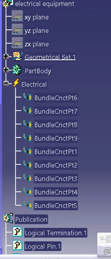
- Define part as electrical connector.
- Define bundle connection point.
- Define connector connection point.
- Define cavity connection point.
CONNECTOR 2 PIN
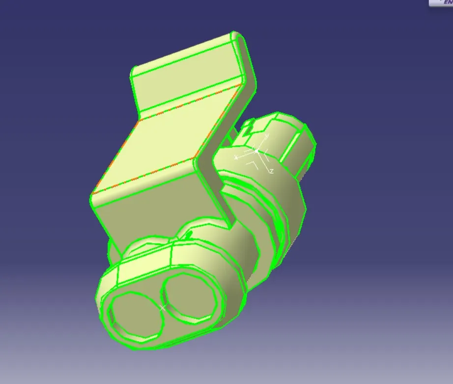
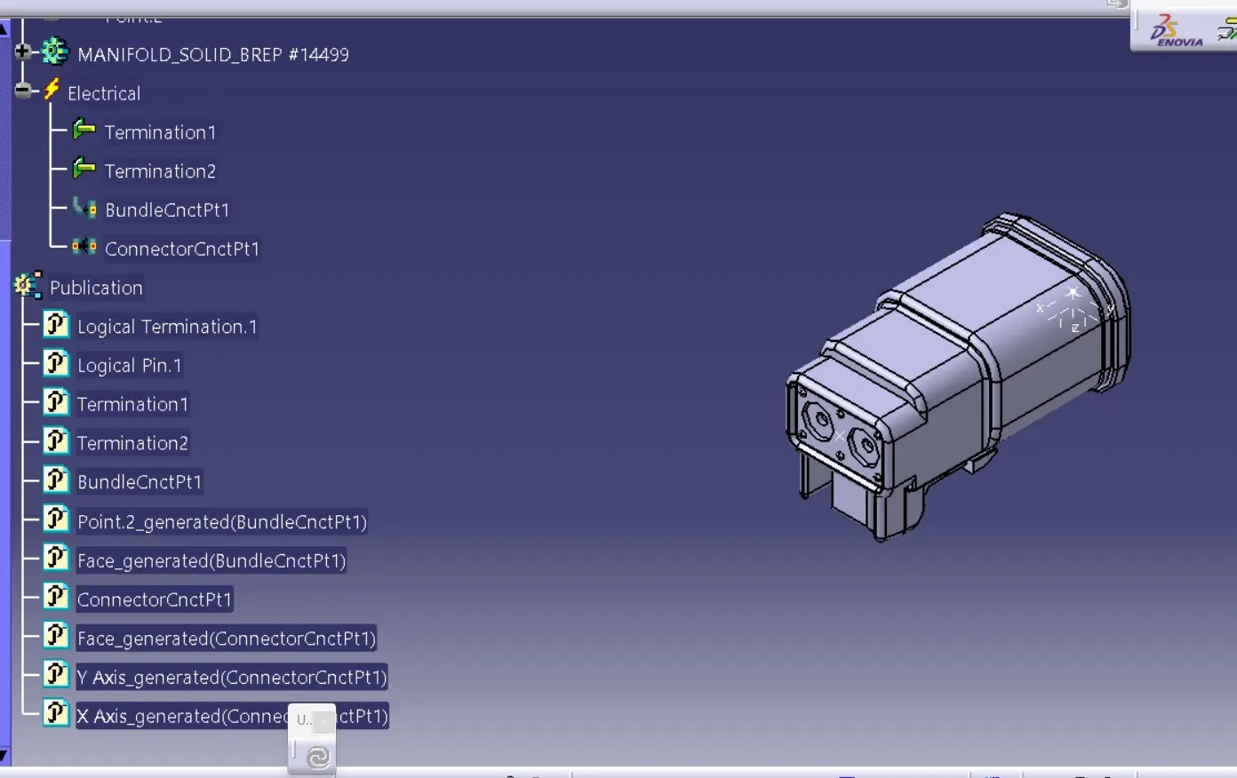
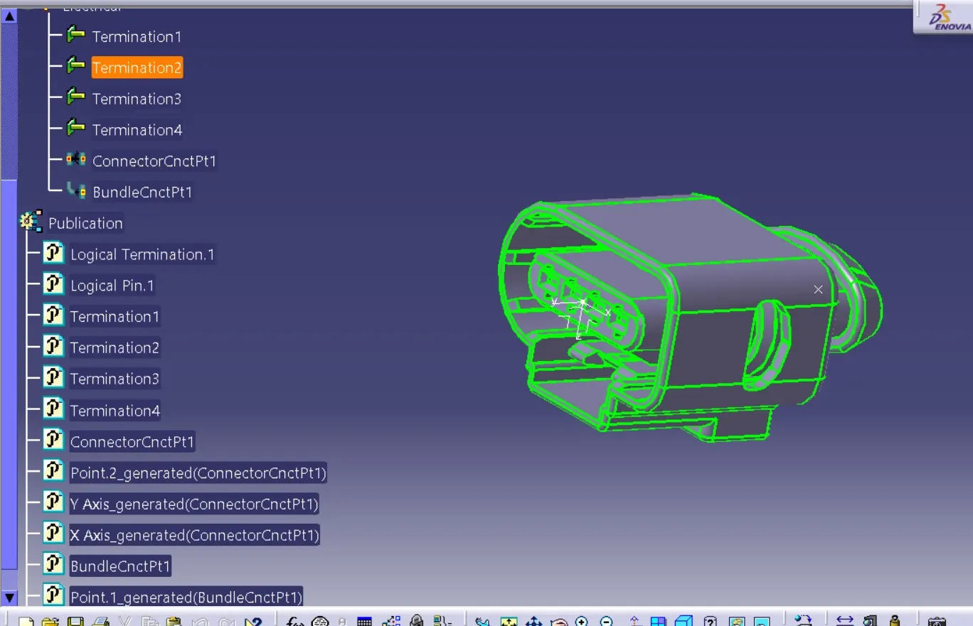
4 PIN CONNECTOR
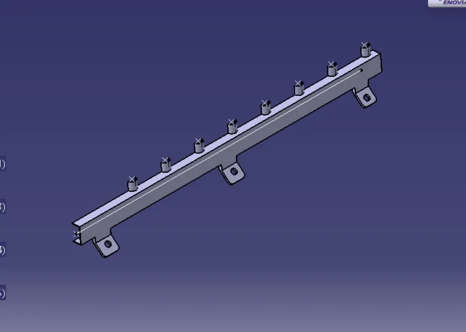
C TYPE BOTTOM CHANNEL
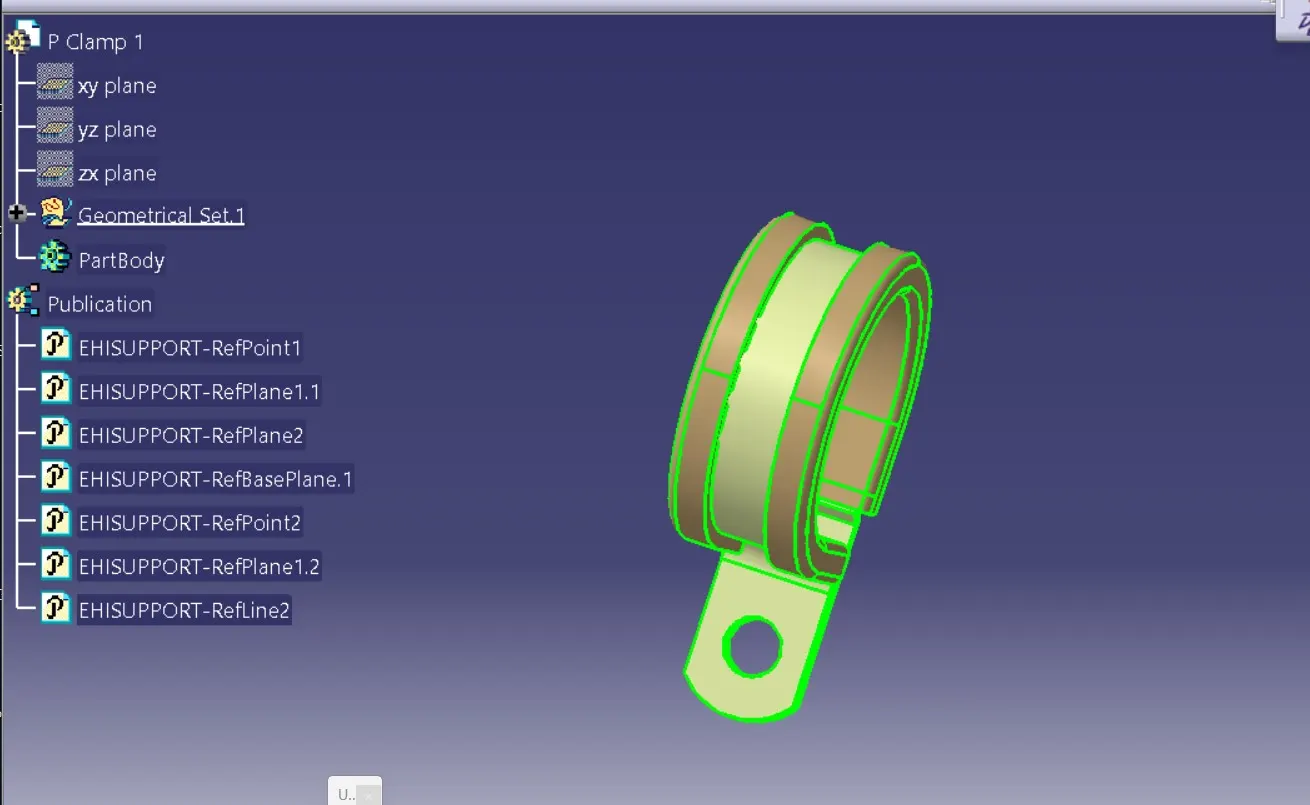
P CLAM
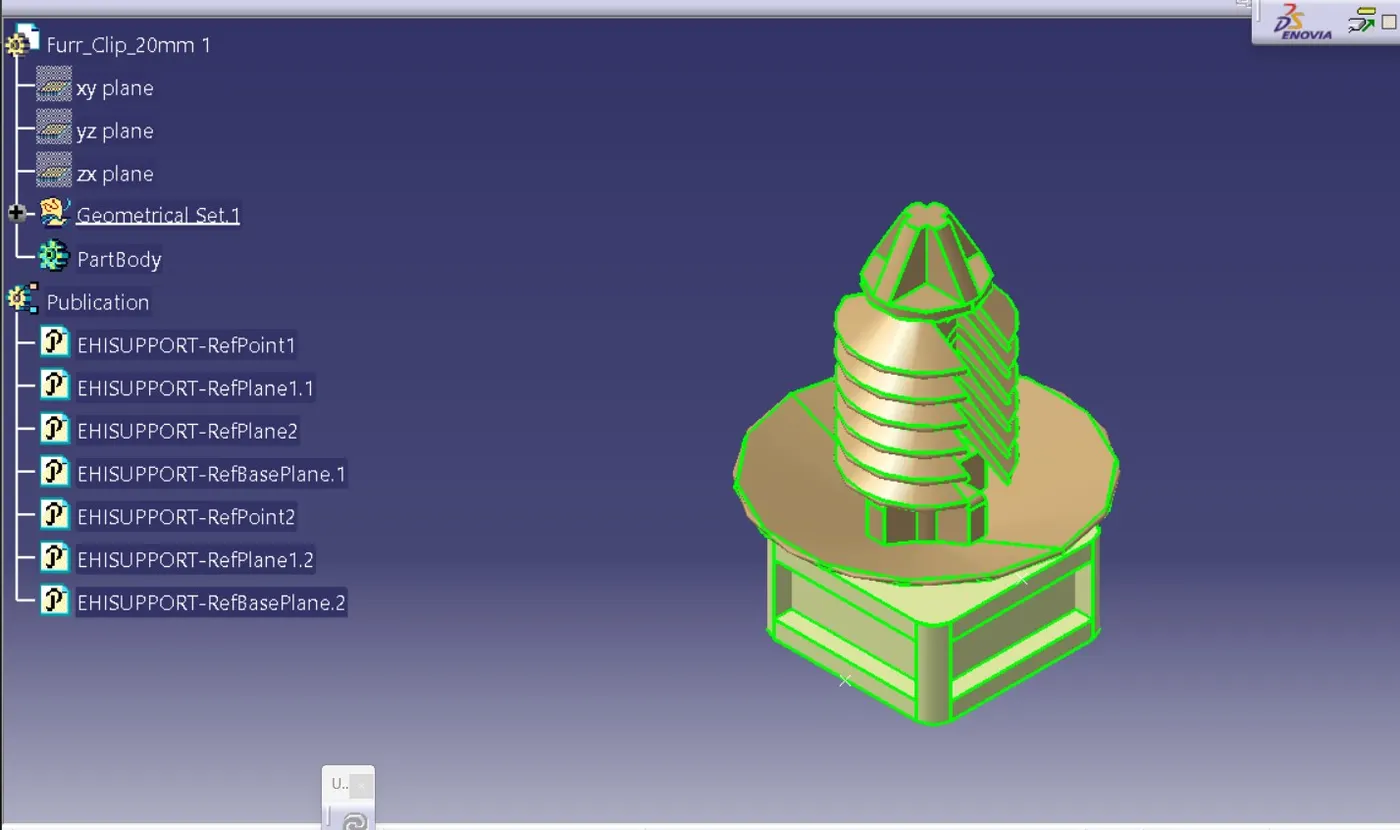
FURR CLIP
4 PIN CONNECTOR
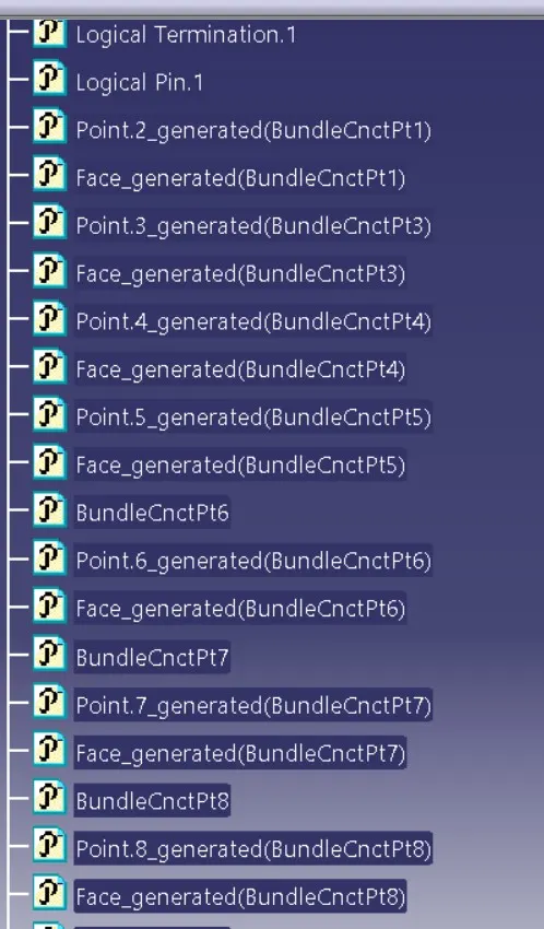
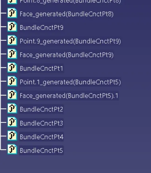
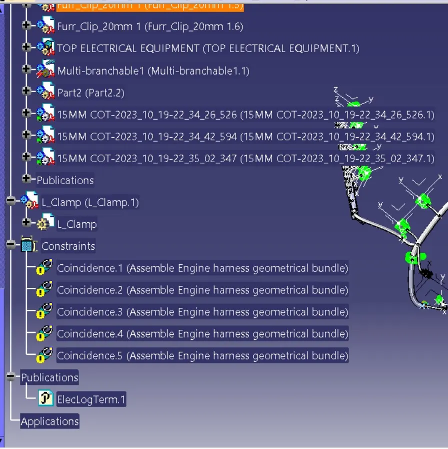
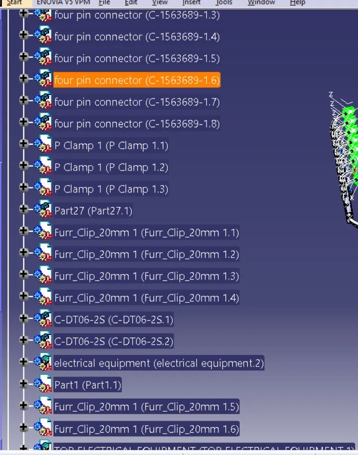
FEATURE TREE
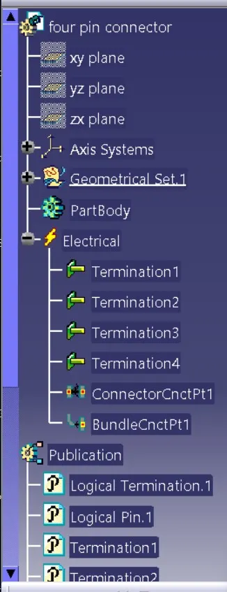
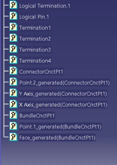
Routing the wiring harness to the connectors :
Go to electrical harness assembly workbench and select geometrical bundle command and select the geometrical bundle in the model tree. Then select the multibranchable command to start the bundle routing and go to route definition.
- The bundle routing starts from interconnection connector and then to the P-clamps and to the guiding channels.
- Addding branching points wherever necessary using add branch point command as shown below.
- Adding branches wherever necessary to connect the various connectors to the main branch as shown below using add branches command and routing definition into it.
- To route the wiring harness through the guiding channels select external curve and click on the line in the guiding channel.
- Add branching points to the wiring bundle and add branches to to connect the wiring to the connectors at the injectors as shown below.
- Add guiding channel top as shown in the image below.
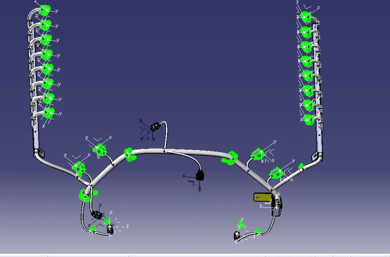
FEATURE TREE
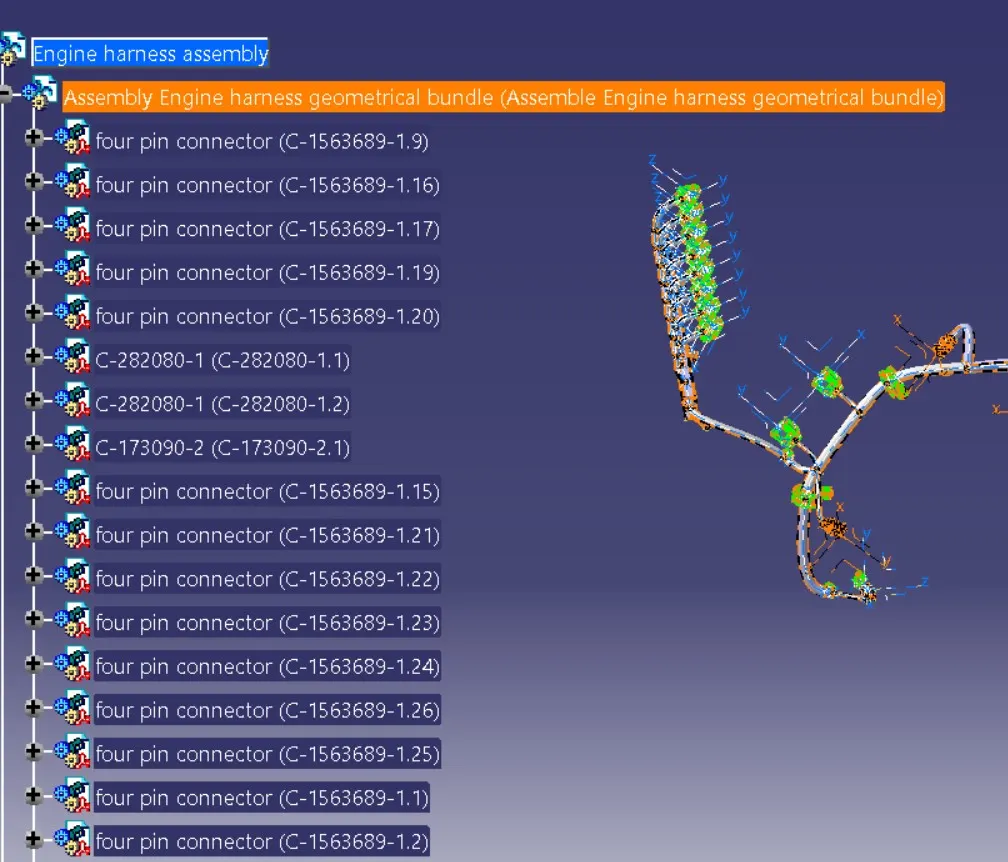
Checking bundle continuity:
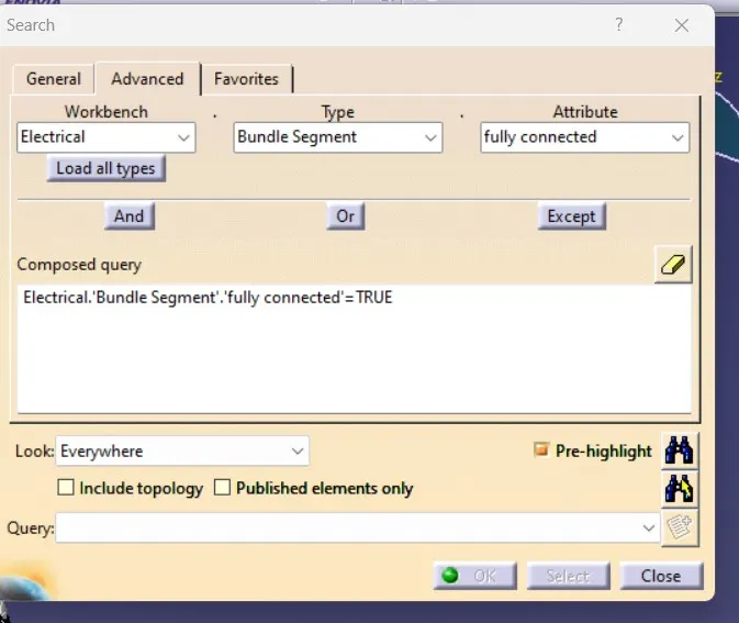
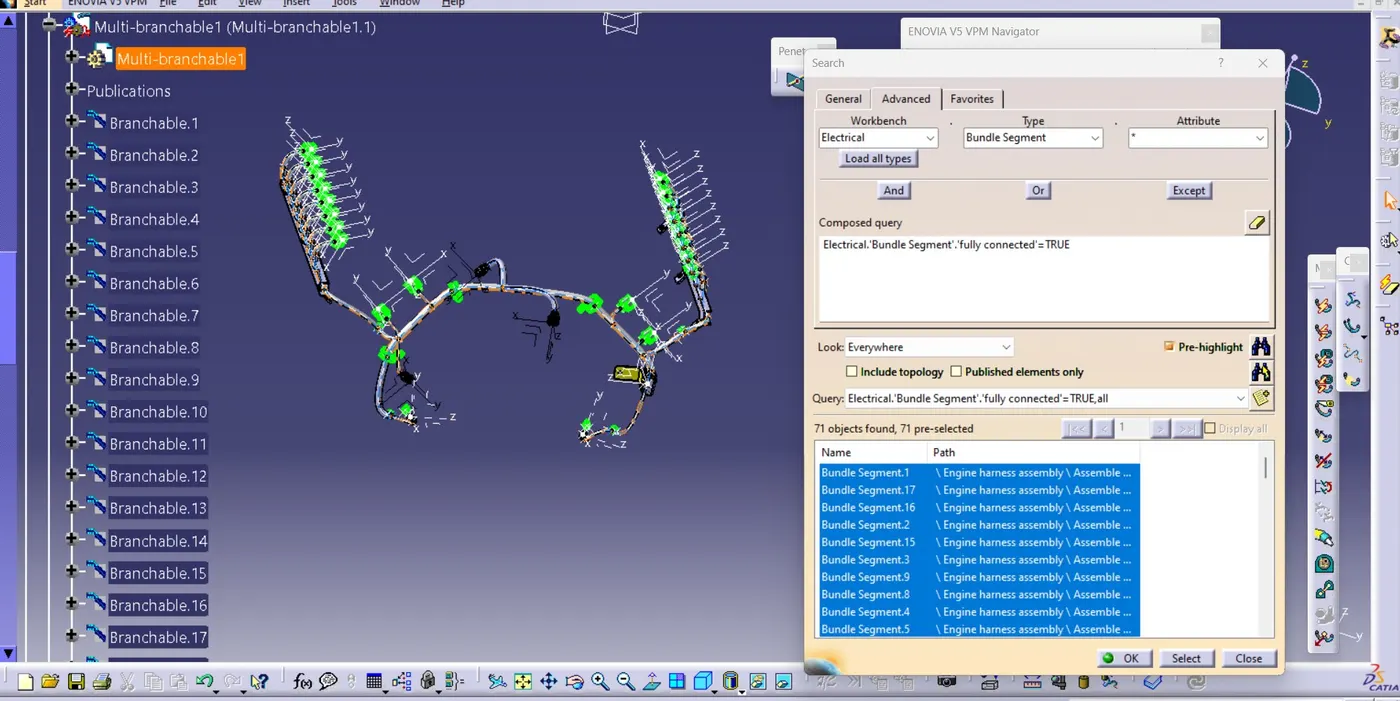
In this step, first we have to make sure that multi-branchable is selected then we have to go in Edit>Search>Advanced>
- By selecting 'True' option will show all the connected bundle segments while selecting 'False' option will show all the non-connected bundle segments.
- Here, we have selected for the 'True' option and searched for results. All the bundle segments are highlighted found showing that all the bundle segments are electrically connected.
FLATTENING HARNESS:
In this step, for creating flatten view we have to work in Electrical Harness Flattening workbench of Catia V5. We should also make sure that the flattening file is saved in the same folder where other files of harness assembly are saved.
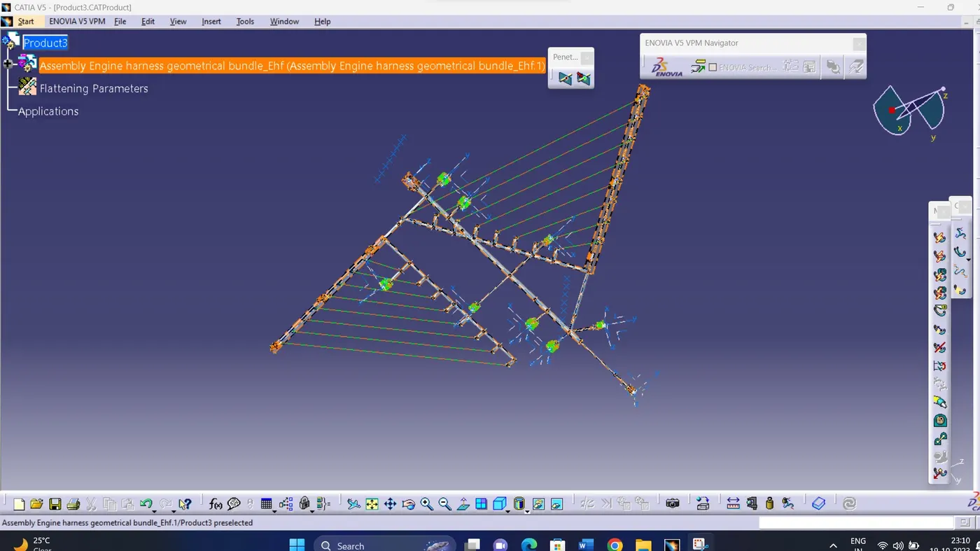
- Before creating flatten view, first we have to define flattening parameters. Make sure that selecting Single line for bundle segment and 'Double' line for protective covering.
- We have extracted the bundle assembly into Engine Harness Flattening Product file and then flattened the file along face of interconnection connector as shown in above figure.
- At this stage, for clarity, we have been hidden the flattening diagram of the plastic guiding channels from the drawing view.
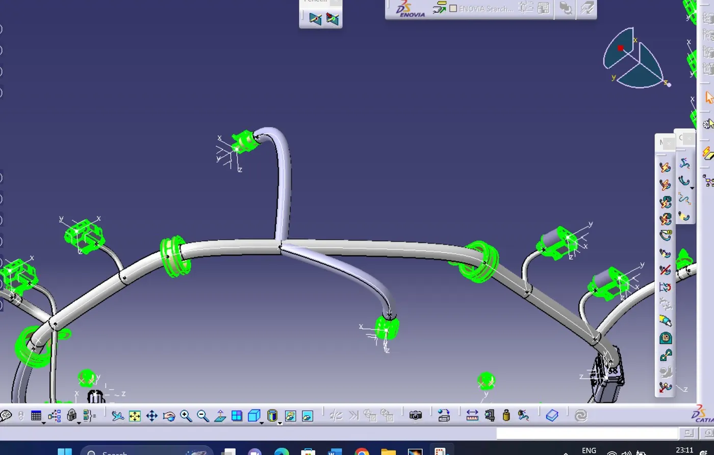
PROTECTIVE COVERING
CONCLUSION:
In this project I have successfully routed the wiring harness for the V16 Engine assembly and the flatten-view drawing was prepared in CATIA V5. Various packaging rules and constraints were considered while routing the harness. After finalizing the wire routing, we can request the corresponding Engine design team to provide additional holes for the mounting of Fir tree clips.