Week 8 - Challenge 3 - Coin Holder Design
COIN HOLDER
OBJECTIVE: Developing the coin holder plastic model design from the give input class A surface by ceating class B and class C surface.
AIM
Create the Coin Holder Plastic component through the given Class-A surface.the tooling axis for the given Class-A Surface should be created meeting the requirements of the draft angle and at the end perform the Draft analysis on the model. the Thickness of the component to be 2.5 mm
CLASS A SURFACE
In automotive design, a class A surface is any of a set of free form surfaces of high efficiency and quality. It gives the aesthetic of the component which is created by the styling team and gives to the part design engineer to create the part with all engineering aspects.
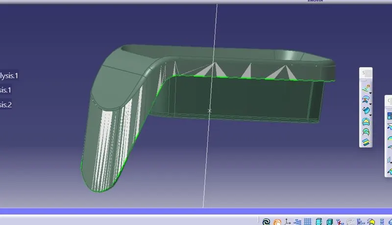
We have been given the Class-A surface and the first thing to do is to make sure that the given surface has no gap in between them. We can check it visually and also with help of Join or boundary commands.
The given surface has one boundaries which are one outer boundary. So, there are no other gaps found.
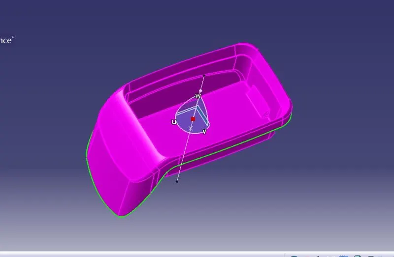
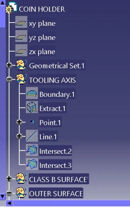
TOOLING AXIS: Tooling axis is the movement direction of the mould and cavity, so it is very important to creat the tooling axis for the plastic product model while design, to analys the draft angle effect for the product. For this model the tooling axis is created by suing normal to surface method. There are different type to creat tooling axis which is mention below:-
- Normal X,Y,Z
- Point and Direction
- Normal to Surface
- Side Core Axis
- Bisecting Method
First we have to analys the model and find the suitable surface where the tooling axis can creat.Then next extract the surface and by using normal to surface option in line creation tool, creat the tooling axis for the model.
Once the tooling axis is created we need to do draft analysis for the given class A surafce
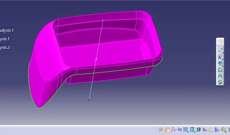
DRAFT ANALYSIS: It is very important to give draft angle to the plastic product to avoid damage or defective product output from the mould. The draft angle using in industries are 3 degree.
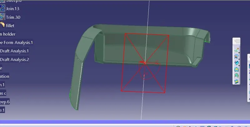
Drag the compus to the tooling axisand kept in center and then click on the compus icon on draft analysis dialogue box, the compus will get active. Once the compus will active again need to aligned along with tooling axis.
Once the compus aligned with tooling axis, click on the model to do the draft analysis, the model is convert into green color then its indicate model is perfect for modeling and if it is showing red in color then click on the draft analysis dialogue box in reverse icon and the model will get turn into green color, after click on reverse icon still the model is in red color the , don't proceed further , and revert back to class A surface engineer.
The below picture showing the draft analysis for the coin holder:-
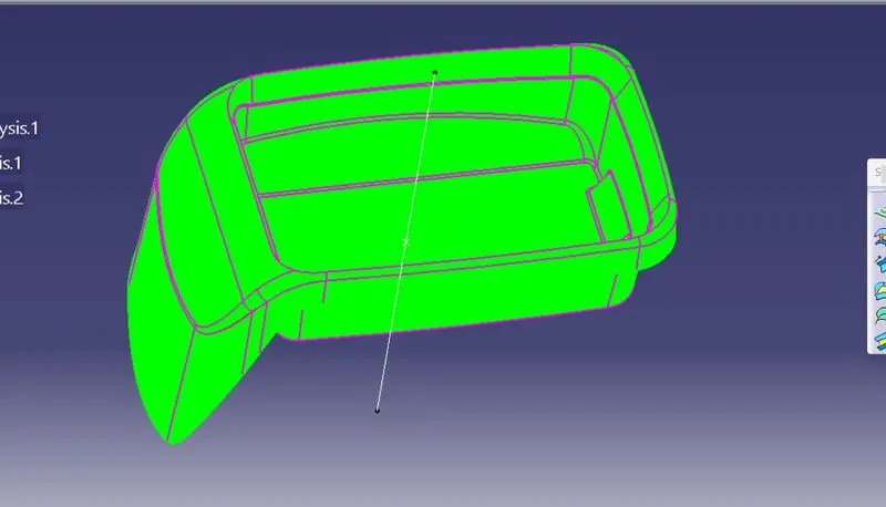
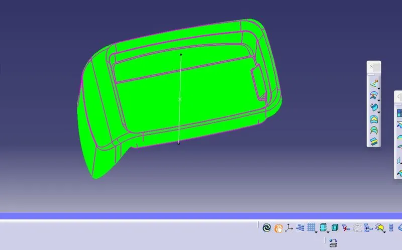
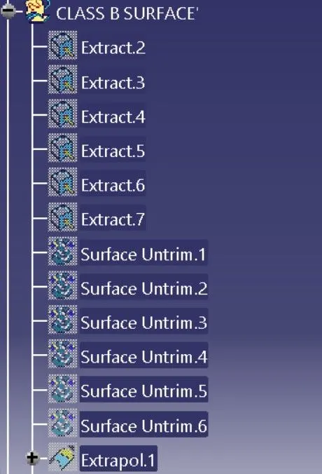
B SURFACE: Once the draft analysis is over for the class A surface , next step is to creat B surface.Analysis the class A surface if the surface is less the proceed with multiple offset, if the class A surface is more surface which is difficult to offest one by one then we have to go for one time offet option.
For this model the number of surface is less , so multiple offset is use for offsetting for surface at given distance or if the distance is not given then we can assume 2.5mm or 3mm.
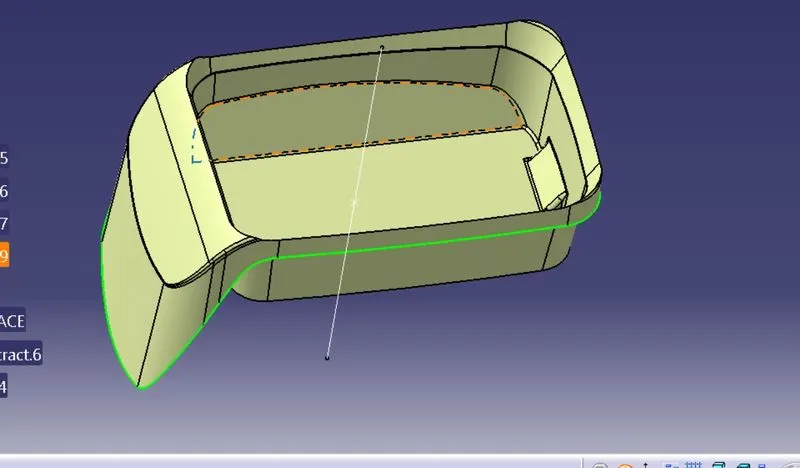
CLASS C SURFACE: The class C surface helps to connect the class A surface and B surface. The C surface is created with the reference of class A surface and tooling axis. When the class C surface is created we have to give the proper angle, if the draft angle is not given then it will creat problem while moulding the product.
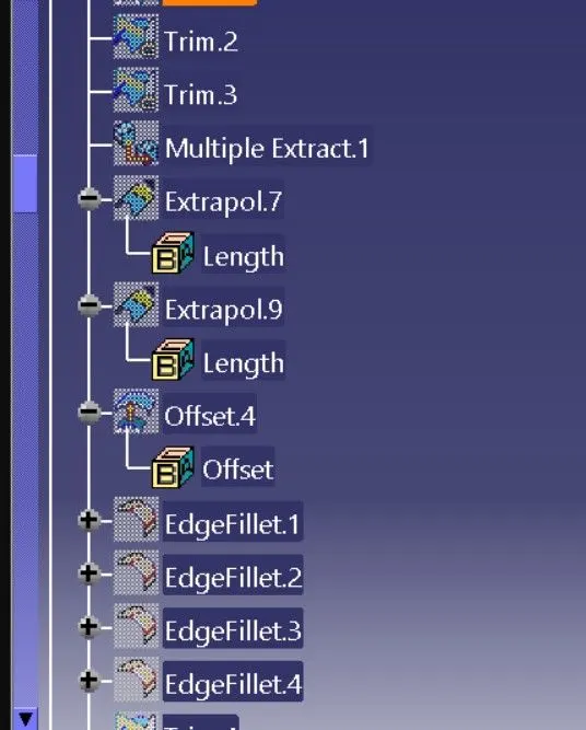
First we have to take the boundary for the class A surface edges and by suing swept commond , the C surface will developed. While developing C surafce we have to give proper draft angle to the surface.
Once th C surface is created then need to check the proper intersection of C surface and B surface. By joining and trimming common we have to join the C surface with the class A surface and after join need to trimmed the C surface from B surface, so at the ned we will get final close surface. Once the close surface will creat do the draft analysis for the close surface.
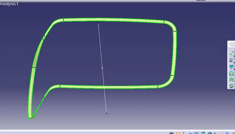
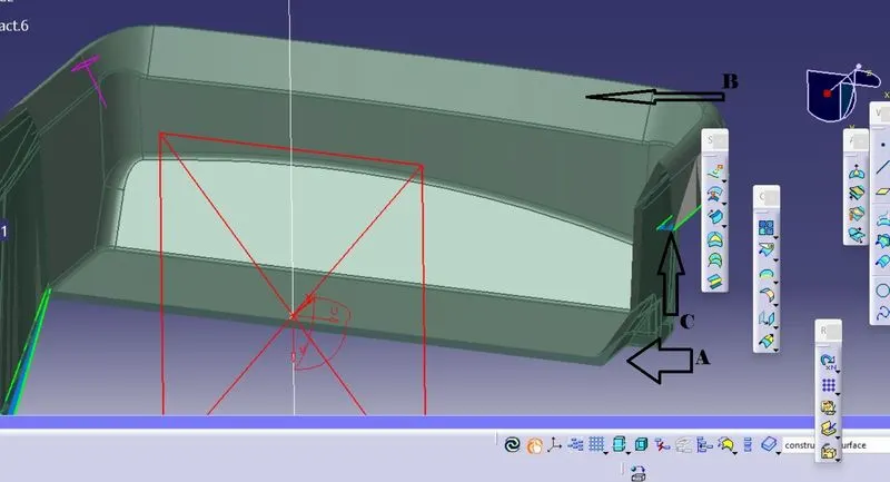
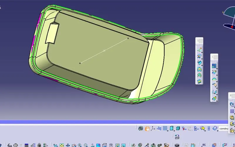
CLASS A+C
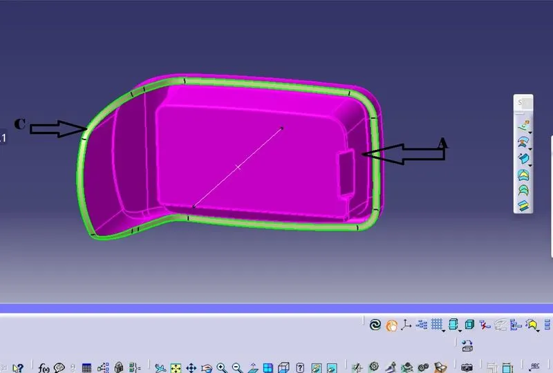
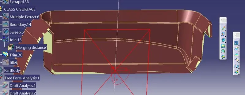
CLASS A+B+C OR CLOSED SURFACE-
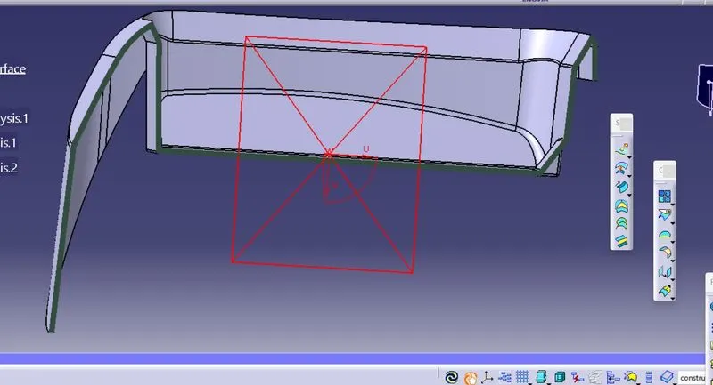
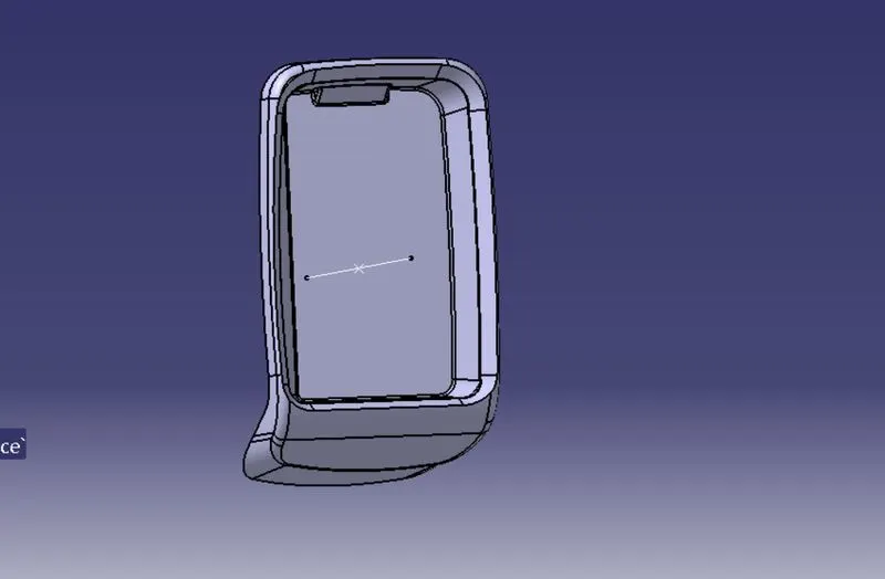
FINAL SOLID BODY: This ia the final stage of the plastic product model,where the final close surface will converted into a solid body.Once the final close surface is created we have to shift to part workbench from surface workbench. In part workbench by using close surface commond the close surface will converted in to solid body.
Once the solid body will created again do the draft analysis for the solid body.
PART BODY
Close Surface feature usedto make a solid body from the surface
DRAFT ANALYSIS OF COMPONENT
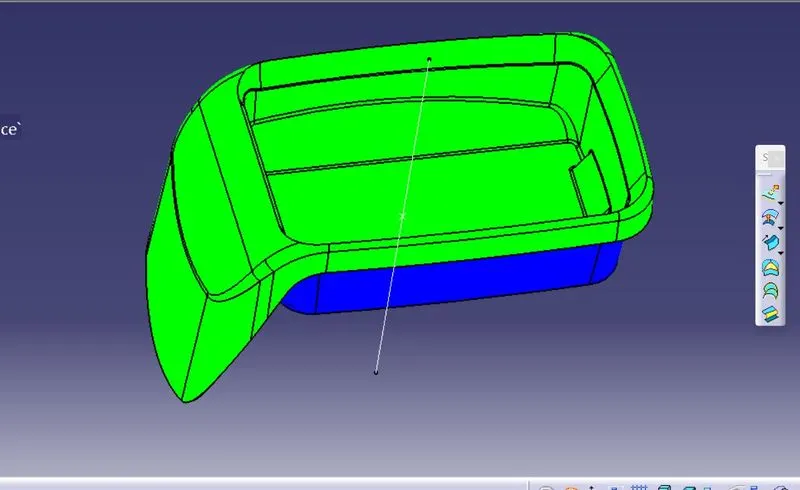
Change the view to material mode for draft anlysis
draft analysis is done using featured draft analysis tool
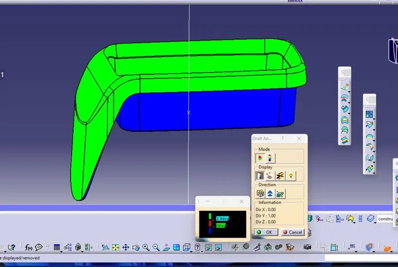
Use the compass fucnction to aling the compass to the tooling direction and lock the direction using lock function in the draft analysis tool bar
the surface is showing green colour so that the surface clears the minimum draft angle of 3 degree
By using the analyses under the running pointwe can check draft angle on the individual faces. It shows how much draft on specific points when we move the cursor point.
Green colour - above 3 degree positive draft
Red colour -between 3 and 0
blue colour- below 0 degree
DIFFERENT TYPE OF VIEW-
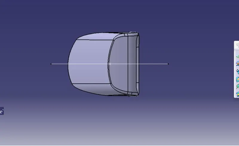
ISO-
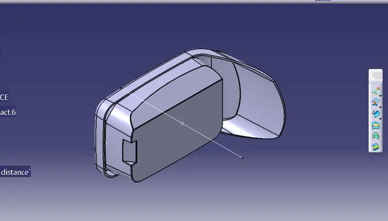
FRONT VIEW-
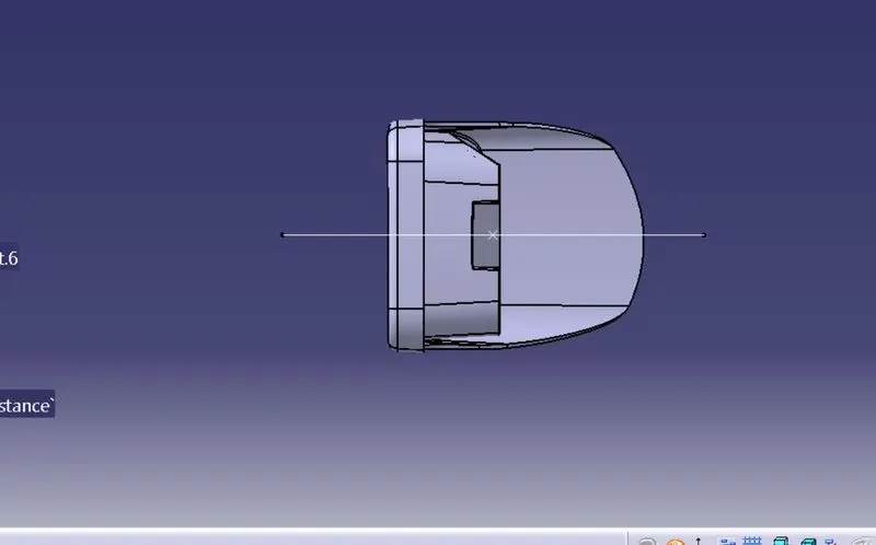
SIDE LEFT VIEW-
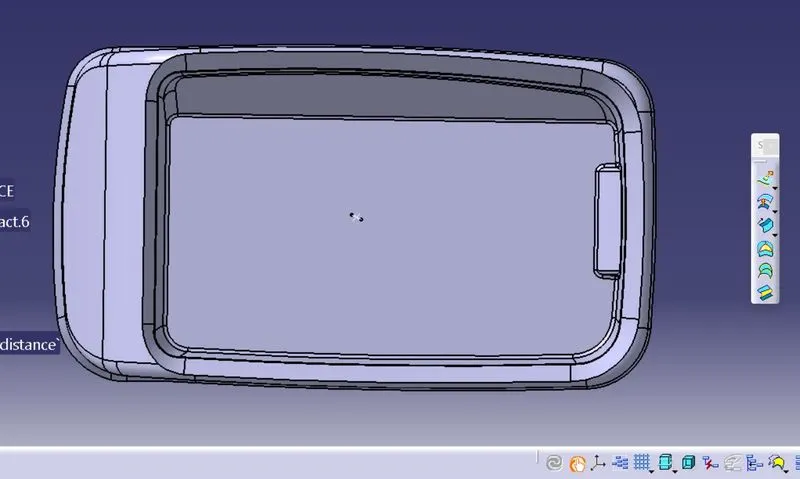
SIDE RIGHT VIEW-
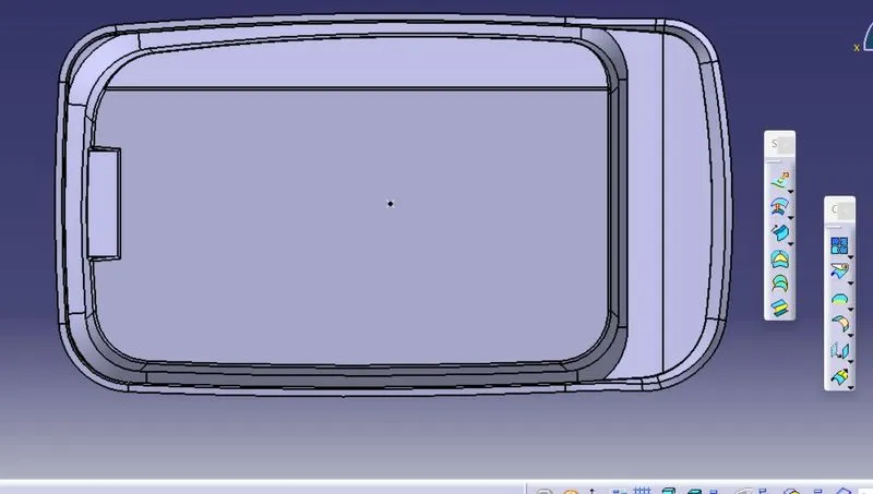
TOP-
BACK-
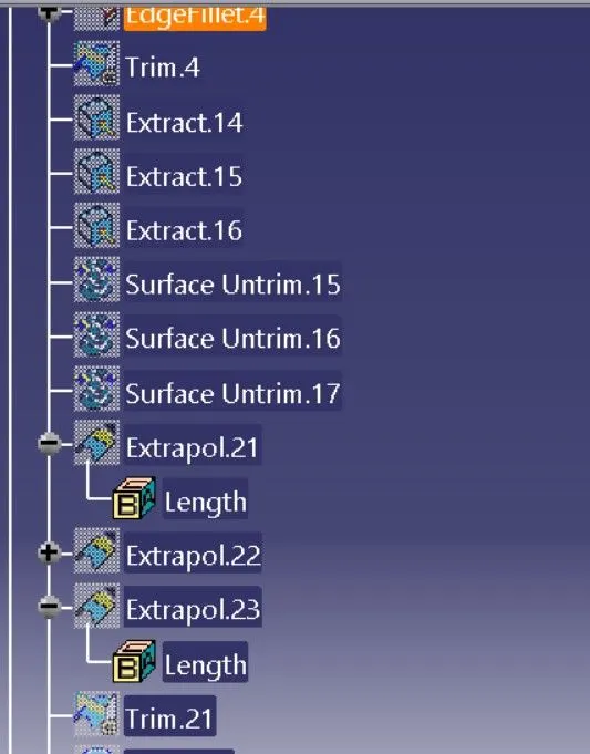
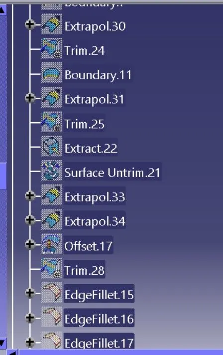
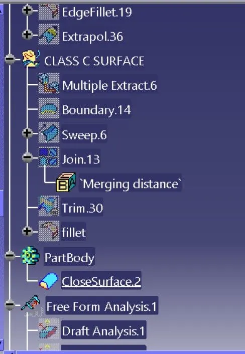
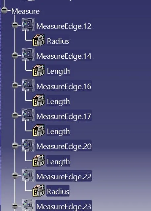
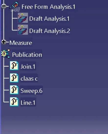
FEATURE TREE-

CONCLUSION-
- Created the Coin Holder component using the given Class-A surface.
- the tooling axis for the given Class-A Surface is created which meeting the requirements of the draft angle
- Draft analysis is done on the CLASS A surface
- Draft analysis is done on the model.
- Using the Close Surface feature solid body is created from the surface
- Publications: Tooling Axis Class A, B, and C surface and closed surface