PASSANGER CAR BACKDOOR DESIGN USING SIEMENS NX_CAD 12.1 - AUTOMOTIVE BIW COMPONENT
OBJUCTIVE:
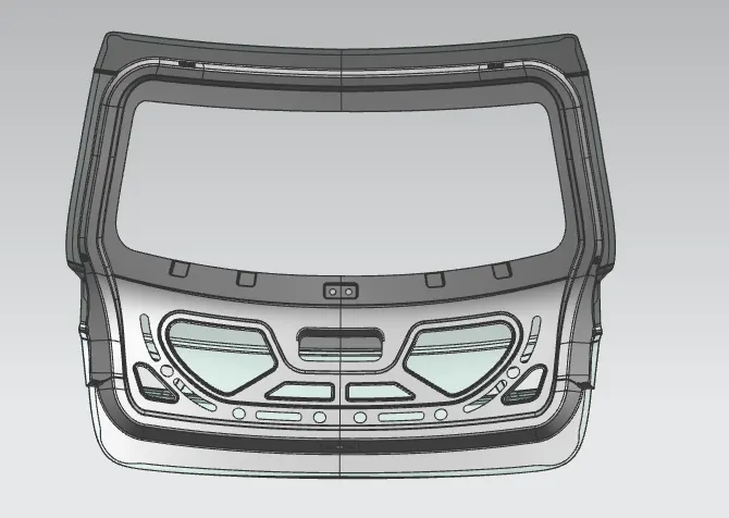
- The main objective of this project is to design a back door of a car with an inner panel , outer panel and reinforcements for hinges , gas stay , wiper motor and latch
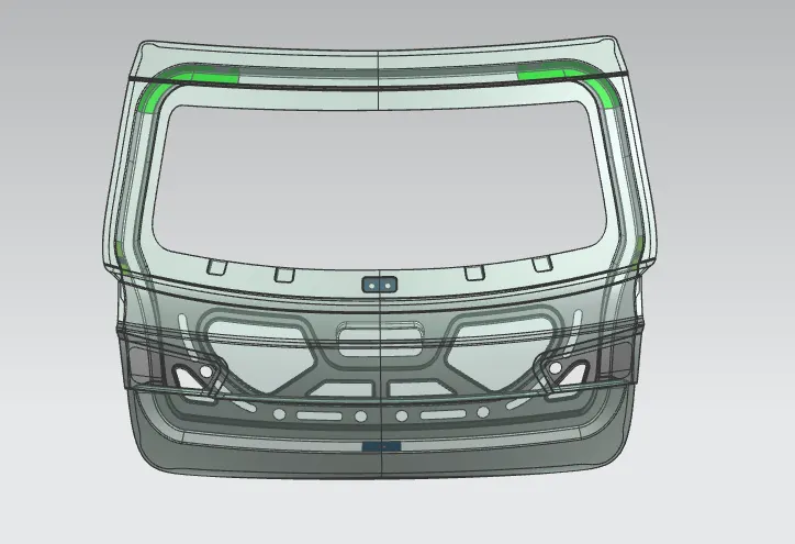
- The inner panel is subjected to the draft analysis to ensure whether it is satisfying the deep drawing requirements for the tooling direction that is created in the design
INTRODUCTION:
What is BIW?
Body in white (BIW) is the stage in automobile manufacturing in which a car body's frame has been joined together, that is before painting and before the motor, chassis sub-assemblies, or trim (glass, door locks/handles, seats, upholstery, electronics, etc.) have been integrated into the structure. Assembly involves different techniques such as welding (spot, MIG/MAG), riveting, clinching, bonding and laser brazing. Body in white refers to the stage in automotive manufacturing when a car’s sheet metal components are welded together which include:
- Hood
- Trunk lid
- Roof
- Front and rear fender
- Side wall
- Side Doors
- Tail Gate (Back Door)
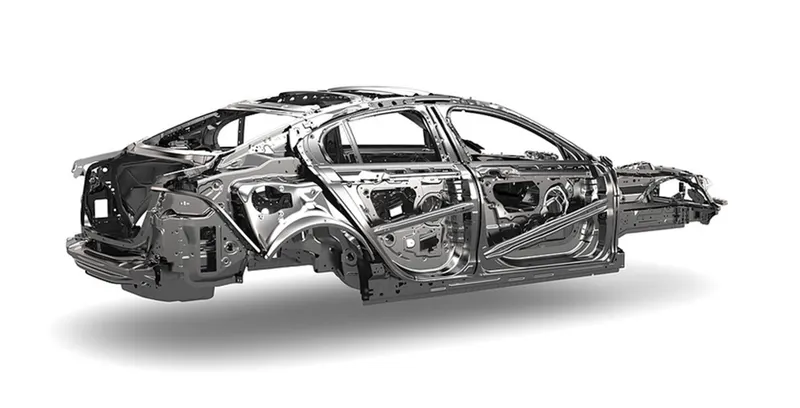
The term BIW derives from manufacturing practices before steel unibody monocoques — when automobile bodies were made by outside firms on a separate chassis with an engine, suspension, and fenders attached. The manufacturers built or purchased wooden bodies (with thin, non-structural metal sheets on the outside) to bolt onto the frame. The bodies were painted white prior to the final color.
A folk etymology for "body in white" is the appearance of a car body after it is dipped into a white bath of primer (undercoat paint)— despite the primer's actual gray color. BIW could also refer to when car bodywork would be made of timber - all timber products, furniture, etc., are considered to be "in the white" when at the stage of raw timber before finishing or varnishing.
In car design, the "body in white" phase is where the final contours of the car body are worked out, in preparation for the ordering of the expensive production stamping die. Extensive computer simulations of crash-worthiness, manufacturability, and automotive aerodynamics are required before a clay model from the design studio can be converted into a body in white ready for production
BACK DOOR :
The back door of the vehicle is also called as tailgate .The back door of the car is the rear most part of the vehicle which gives access to the trunk space of the vehicle .The back door is one of the closure commodities in BIW sheet metal design . The material used for the back door manufacturing depends on the budget and performance of the vehicle . mostly aluminium and steel is used for the manufacturing where as the steel is used on the low budget cars where it can be easily produced with less cost effective by following the stamping process.
BACK DOOR PARTS :
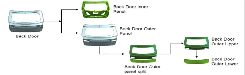
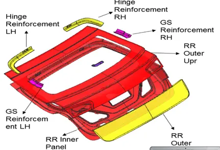
The back door consists of the following basic components :
- Back door outer panel ( upper)
- Back door outer panel (lower)
- Back door inner panel
- Hinge reinforcements
- Gas stay reinforcements
- Latch and striker reinforcements
- Wiper motor reinforcements
-
DESIGN INTENT :
The intent of this project is design the BIW back door of the vehicle by following the engineering standards and manufacturing requirements which satisfies the deep drawing process .
DESIGN CONSIDERATIONS :
- Functional requirements of hing and gas stay
- Rear visibility criteria
- Boot space
- Crash analysis
- Bend test , dent test , torsion test & endurance test
- Rear crash regulation
- Gap and flushness requirements
TOOLING DIRECTION TO BE CONSIDERED :
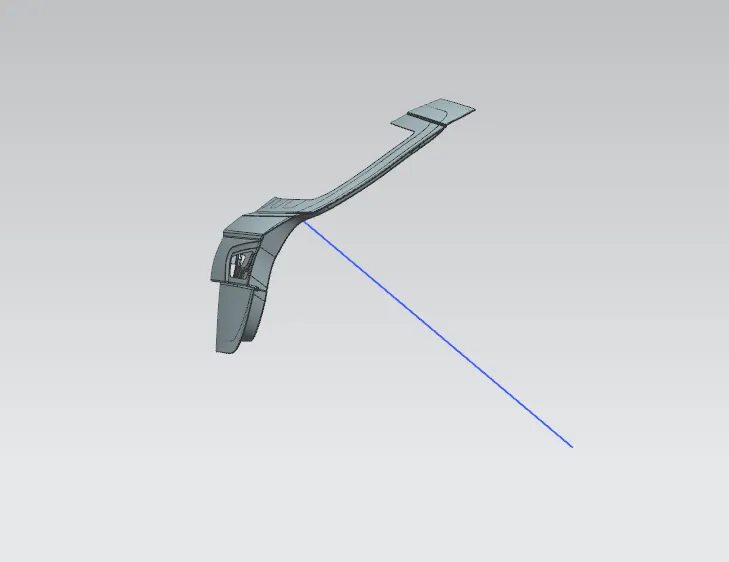
- Initially the tooling direction is created for deep drawing purpose before designing the inner panel
- Then styling surface is analyzed and irregularities are fixed
- Then backdoor was designed using the top down approach
Latch and striker trajectory
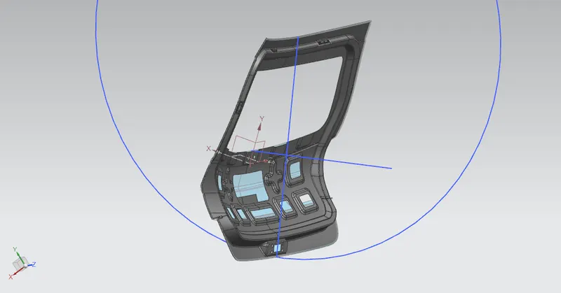
To define the opening and closing trajectory, the hinge and latch are positioned based on the hinge axis and trajectory. The circle drawn should perpendicular to the latch striker to satisfy the condition. Based on the rotation trajectory the hinge axis, latch striker and predefined Gas stay are correlated for smooth kinematics of door opening and closing.
INNER PANEL:
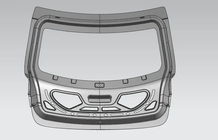
The inner door panel is a component which is used for strengthening the door assembly and it is one of the most important components on which all accessories are mounted like hinges, glass guide channel, moulded trim, latch etc. The possible method is the integration method. In the integration method, the part is stamped out of a single blank. This reduces the number of tools needed; the assembly cost and eliminates any fit ability problem.
Outer panel:
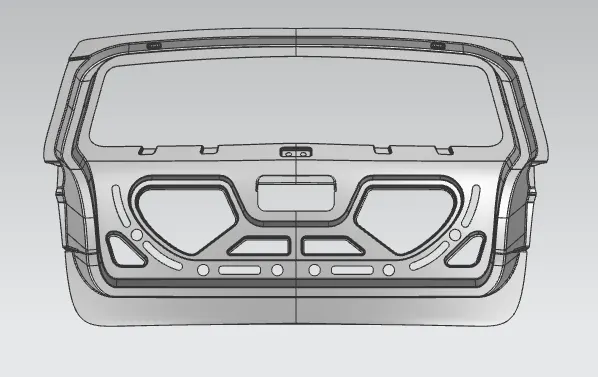
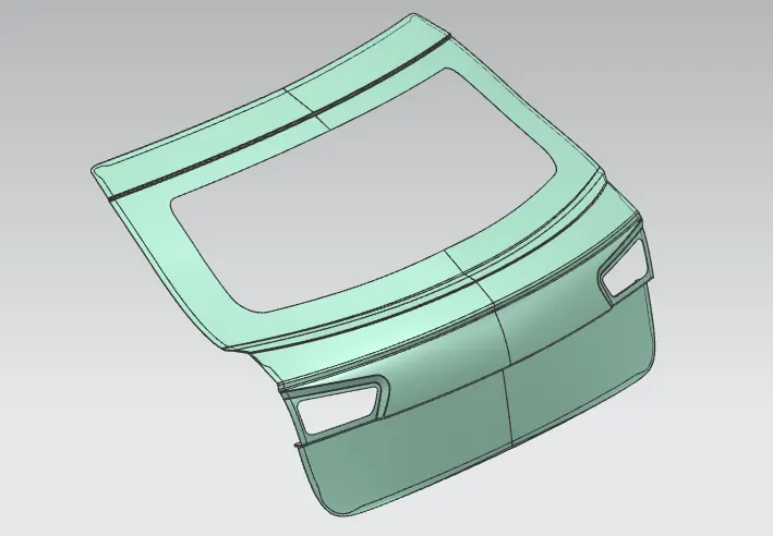
The outer panel of the back door is similar to other BIW components where it is the aesthetic part of a vehicle. The coating provided is of multi-stage which has the property of scratch resistance, rust prevention and smooth and attractive finishes. The outer panel also has the provisions for the tail lamp, rear fog lamp and also has the provision for licence plate mountings. Most of the hatchback cars have the provision for wiper motor.
REINFORCEMENT:
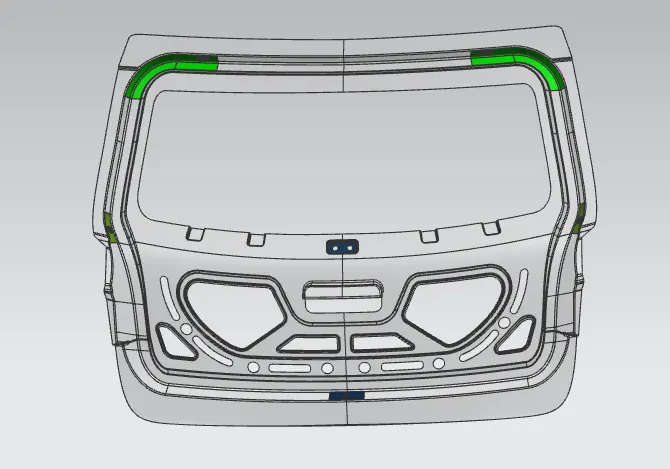
The reinforcement provided is of 4 numbers which consist of hinge reinforcement, gas stay reinforcement, wiper motor reinforcement and latch/striker reinforcement.
HEMMING OPERATION:
Hemming is a mechanical joint design which is used for joining inner and outer closure panels as found indoors, hoods, bonnets and lift gates. To increase crash resistance the gap between the hemmed panels is filled with a high-strength adhesive which also prevents from corrosion.
Hemming relief:
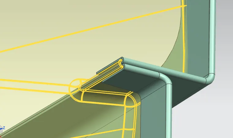
Hemming reliefs are cut-outs which are provided on the hemmed corner of the panel assembly which in turn to avoid some of the hemming defects such as wave-like OR wrinkle formed surface as shown below:
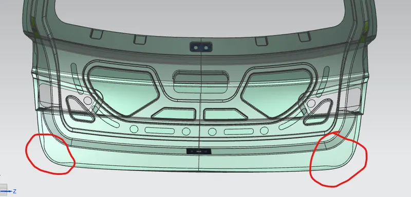
The back door design requires two locations where the roller type hemming relief is required which are shown below:
DRAFT ANALYSIS :
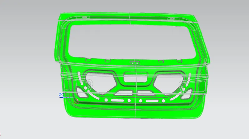
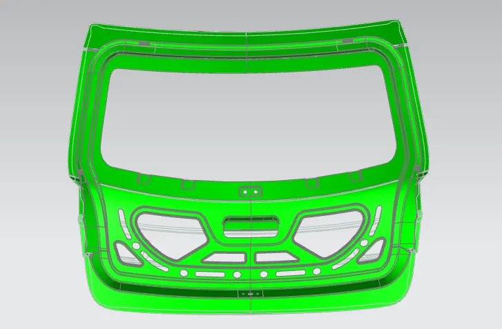
The Draft Analysis command enables you to detect if the part you drafted will be easily produced. This type of analysis is performed based on color ranges identifying zones on the analyzed element where the deviation from the draft direction at any point, corresponds to specified values.Minimum draft angle of 70 is considered for analysis . green colour infer on the parts that all face along the tooling direction has positive draft angle greater than 70 and passed in analysis
PROCEDURE FOR DESIGNING THE BACK DOOR :
WAY OF APPROACH : TOP DOWN ASSEMBLY
ASSEMBLY :
There are two types of assembly , they are
- Bottom-up assembly
- Top-down assembly
Bottom -up assembly:
The bottom-up assembly is the most preferred approach for creating assembly models . In this type of assembly the components are created in part design work bench ( As nx cad part) file. Parts are conceived in assembly design workbench using product structure tools . After inserting each component,constraints are applied to position them properly in the 3d space with respect to the other components. This assembly is preferred for large assemblies, especially those having intricate individual components .
Top -down assembly :
In the top assembly design approach, components are created inside the assembly design workbench . There fore , there is no need to create separate part files of the components. This design approach is completely different from the bottom-up design approach. Here you have to create the product file first and then one by one create all the components. Note that even then the parts are created the product file , they are saved and opened individually one by one when they are needed . Here the construction and the assembly takes place simultaneously
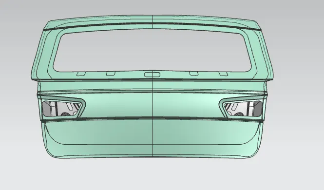
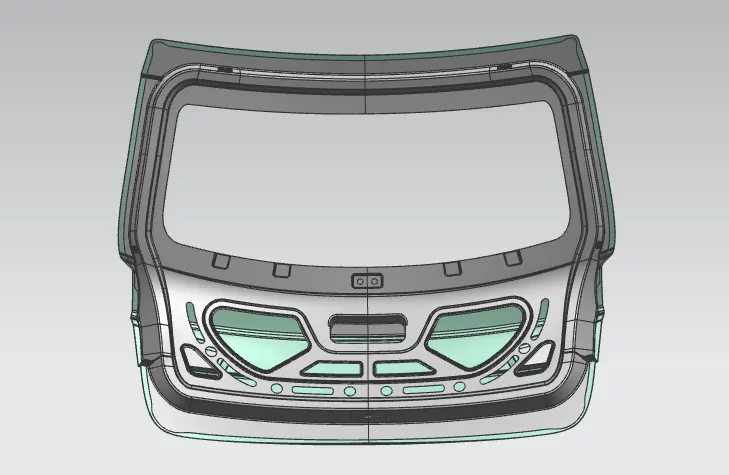
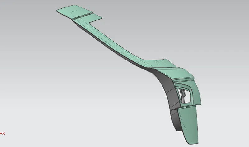
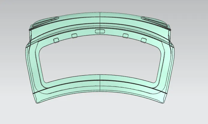
DIFFERNT VIEWS OF BACK DOOR
FRONT VIEW
 .
.
BACK VIEW
SIDE VIEW
TOPVIEW
CONCLUSION:
Thus the Back door was designed and developed from the given styling surface with essential Reinforcements and Emboss. To satisfies the manufacturing requirements Draft analysis was also done on the Inner Panel