3D-CAD MODELLING OF AN AMERICAN CHOPPER WITH PHOTO-REALISTIC RENDERING USING SOLIDWORKS
INTRODUCTION
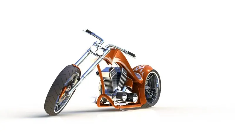
The purpose of this project is to create an aesthetic CAD model of an AMERICAN CHOPPER BIKE using Solidworks and photo-realistic rendering using Solidworks Visualize.
AMERICAN CHOPPER - A chopper is a type of custom motorcycle. The chopper is perhaps the most extreme of all custom styles, often using radically modified steering angles and lengthened forks for a stretched-out appearance.
The first choppers were built in America and tended to be based on Harley-Davidson motorcycles. Rather than being primarily performance-oriented modifications, choppers are more about achieving a certain look.
OBJECTIVE
- To design every individual component of the chopper bike with suitable appearances
- To assemble all parts of the chopper in the appropriate position with proper mates
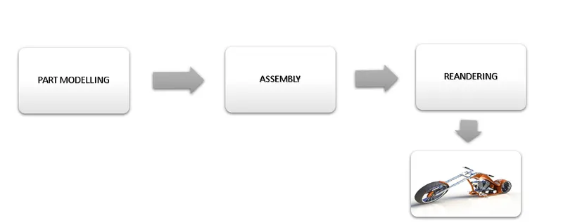
- Finally rendering the fully assembled AMERICAN CHOPPER to get photo-realistic view using solidworks visualize
SOFTWARE USED
- SOLIDWORKS (2021)
- SOLIDWORKS VISUALIZE( 2021)
SOLIDWORKS – It is used to develop mechatronics systems from beginning to end. At the initial stage, the software is used for planning, visual ideation, modelling, feasibility assessment, prototyping, and project management. The software is then used for design and building of mechanical, electrical, and software elements
SOLIDWORKS VISULIZE- It allows you to leverage your 3D CAD data to create photo-quality content in the fastest and easiest way you can–from images to animations, interactive web content, and immersive Virtual Reality. Bring your products to life. SOLIDWORKS Visualize is the “camera” for your CAD data
DESIGN APPROACH
DESIGN METHODOLOGY
PARTS OF AMERICAN CHOPPER
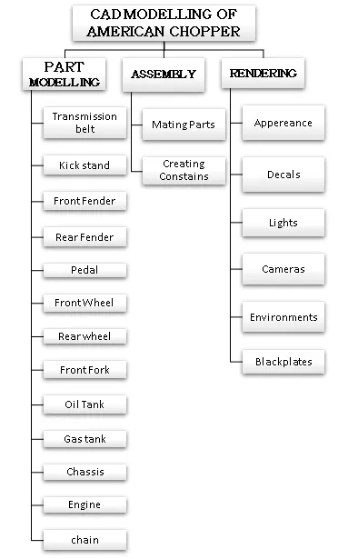
AMERICAN CHOPPER consists of 13 main components they are as follow
- Transmission belt
- Kick stand
- Front Fender
- Rear Fender
- Pedal
- Front Wheel
- Rear wheel
- Front Fork
- Oil Tank
- Gas tank
- Engine
- chain
FEATURES DESCRIPTION
SKETCH:
- Sketch is a two-dimensional representation of the model with respect to the plane /view from the outside of the model. There are distinct sketch possibilities available
in solid works to create a sketch. These are referred to in solid works as Entities. The following are the parts available in Line, Arc, Spline, Circles, Rectangular solid works.
OFFSET:
- A specified distance includes one or more sketch entities, selected model edges, or model faces. For example, you may offset sketch entities such as
splines or arcs, model edge sets, loops, and so on. Finite lines, circles, and splines may be offset.
EXTRUDE BOSS/BASS:
- Extrude is a form of function available for transforming a 2D sketch into a 3D model in solid works.
LOFTED BOSS/BASS:
- The loft function creates a single feature to produce complex geometry. It provides this by interpolating surfaces between a model's different cross-sections. Sketches, faces, or edges
maybe these cross-sections. These cross-sections are called 'Loft Profiles' in the loft interface.
FILLET:
- A rounded internal or external face on the component is created by Fillet / Round. All the edges of a face, selected sets of faces, selected edges, or edge loops can be filled.
CHAMFER:
- A cut on something's edge or corner that makes it slope slightly instead of being perfectly accurate.
SPLIT:
- The Split tool is used to project an object onto other surfaces or curved / planar faces (sketch, solid, surface, face, plane, or surface spline). You're also capable of splitting faces into
different bodies with one order.
DOME:
- Choose one or two planar or non-planar faces. For faces whose centroid lies outside the face, you can apply domes. This helps you to add domes to contours which are irregularly shape.
EXTRUDE CUT:
- Another great feature, extrude cut, helps remove materials from the 3D model. It is just the opposite of the boss / base extrude feature, since while extruding, it cuts a sketch profile.
You can cut in both directions and use them exclusively to create holes, channels, slots, etc.
REVOLVE:
- Create a sketch containing one or more profiles and a centreline, line, or edge that can be used as the axis around which the feature revolves. Tap on one of
the following revolving tools.
DYNAMIC MIRROR:
- The important tool in solid works is the Dynamic Mirror. When you sketch the entities, the pre-selected sketch entity mirrors them.
COMBINE:
- Combine is the type of feature available for manually merging the two bodies in solid works.
TRIM ENTITIES:
- Based on the entities you choose to trim or expand, pick the trim form. With 2D sketches and 2D sketches on 3D planes, all trim forms are available. Any of the following trim
options can be used: Power trim.
SHELL:
- For determining the thickness of thin and thick shell components, the Shell Definition Property Manager is used.
LINEAR PATTERN:
- To create a different number of instances needed to create the pattern linearly, the linear parent bodies / features are used.
CIRCULAR PATTERN:
- To generate a different number of instances needed to create the pattern circularly, the circular parent bodies / functions are used.
SURFACE MODELING:
- Surface modelling allows you the opportunity to produce a visual depiction of the exterior of an object and its contours. It is, in other words, a surface. Parts such as the seat and
the classic 350 fuel tank are surface-modelled.
APPEARANCES:
- An appearance, including colours and textures, determines the visual properties of a model. Physical properties, which are determined by materials, are not affected by appearances.
A default appearance that emulates the look of the material is given to any material.
DESCRIPTION OF THE PARTS AND FEATURE USED
1.TRANSMISSION BELT
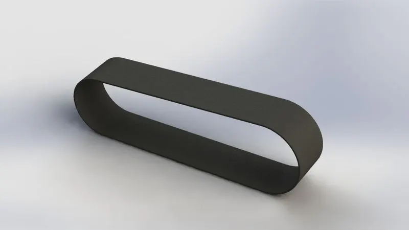
Transmission Belt is a loop of flexible material used to transmit power by the means of pulleys. Belts transmit power efficiently through the pulleys. They are one of the cheapest means used power transmission. other advantages are noiseless working, shock absorption during working, no lubrication, minimal maintenance, high tolerance for misalignment. Transmission Belt is the first part taught in this ultimate SolidWorks tutorial
COMMAND USED
Feature Tools: Extruded Boss & Fillet.
Sketch Tools: Line, arc, Offset Entities
Appearance -Matte Rubber
Procedure
- Select front plane to sketch and draw a horizontal line with line command followed by an 3point arc with tangent and coincidence relation
- Draw another line from end of the arc and join both line by another arc
- Select the lines and arcs give inward offset of 3mm and exit the sketch
- Extrude the sketch with given dimension
- Give fillet to all edges to get smooth finish
- Finally apply appropriate appearances to the belt as matte rubber
2.KICK STAND
A kickstand is a device on a motorcycle that allows the bike to be kept upright without leaning against another object or the aid of a person. A kickstand is usually a piece of metal that flips down from the frame and makes contact with the ground.
COMMAND USED
Feature Tools: lofted boss, extrude cut
Sketch Tools: spline, ellipse, circle, line
Appearance -chrome plate
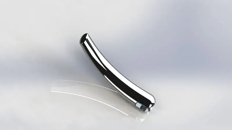
PROCEDURE
- Select appropriate plane, then create fully defined sketch as per the blue print with ellipse and spline
- Extrude the sketch with the lofted boss
- create another sketch on the right plane, draw a centre rectangle at the origin and exit the sketch
- Apply extrude cut with the second sketch
- On the extruded surface draw a circle with appropriate dimension
- Extrude the 3rd sketch with “upto next” option
- Finally apply Appearance - chrome plate
3.FRONT FENDER
Front fender panels are located on the sides of each front wheel. Its primary purpose is to prevent sand, mud, rocks, liquids, and other road spray from being thrown into the air by the rotating tire
.
COMMAND USED
Feature Tools: revolve boss, fillet, split
Sketch Tools: spline, line, sketch fillet
Appearance -chrome plate, sienna paint
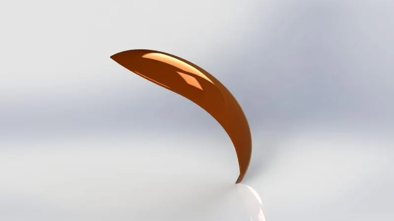
PROCEDURE
- Select appropriate plane, then create fully defined sketch as per the blue print with LINE commend
- Revolve the first sketch with revolve boss tool as reference to the central axis
- Create another sketch in front plane with spline commend by appropriate dimension
- With 2nd sketch using split commend cut the four edges to get smooth curvature
- Apply fillet to all edges for smooth finish
- Finally apply appearance - chrome plate and sienna paint
4.REAR FENDER
Fender are what will keep you from having a skunk stripe on your backside if you ride in the rain, and a front fender will help protect your feet and ankles from spray if you're riding in the rain or even through a puddle.
COMMAND USED
Feature Tools: revolve boss, fillet, split
Sketch Tools: spline, line, sketch fillet
Appearance -chrome plate, sienna paint
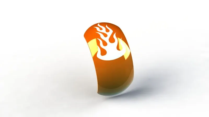
PROCEDURE
- Select appropriate plane, then create fully defined sketch as per the blue print with LINE commend
- Revolve the first sketch with revolve boss tool as reference to the central axis
- Create another sketch in front plane with spline commend by appropriate dimension
- With 2nd sketch using split commend cut the four edges to get smooth curvature
- Apply fillet to all edges for smooth finish
- Finally apply appearance - chrome plate and sienna paint
5.PEDAL
This pedal applies the brake to the rear wheel and is usually located to the right side of the motorcycle, just in front of the footrest. this also used for change gears which is located to the left of the motorcycle
COMMAND USED
Feature Tools: Extrude boss, fillet, linear pattern, doom
Sketch Tools: spline, line, circle,
Appearance -chrome plate
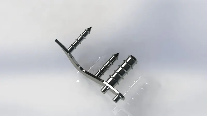
PROCEDURE
- Select appropriate plane, then create fully defined sketch as per the blue print with LINE, SPLINE, CIRCLE commend
- After that extrude the sketch as per the given dimension with extrude boss commend
- Also extrude the circles on the side surface on the pedal with appropriate dimension
- Then draw a sketch on the top plane with line commend then revolve around the construction line with revolve boss
- Create doom over the revolved surface then apply fillet to the doom and the small circle extrusions that were previously created.
- After that extrude the circle and give fillet
- At last give chamfer to edges with appropriate dimensions
- Finally apply Appearance -chrome plate
6.OIL TANK
An oil tank is a safe container for flammable fluids. Though any storage tank for fuel may be so-called, the term is typically applied to part of an engine system in which the fuel is stored and propelled (fuel pump) or released (pressurized gas) into an engine. Fuel tanks range in size and complexity from the small plastic tank of a butane lighter to the multi-chambered cryogenic space shuttle eternal tank.
COMMAND USED
Feature Tools: revolve boss, fillet, split, chamfer, combine
Sketch Tools: spline, line, sketch fillet, construction line
Appearance -white and sienna paint
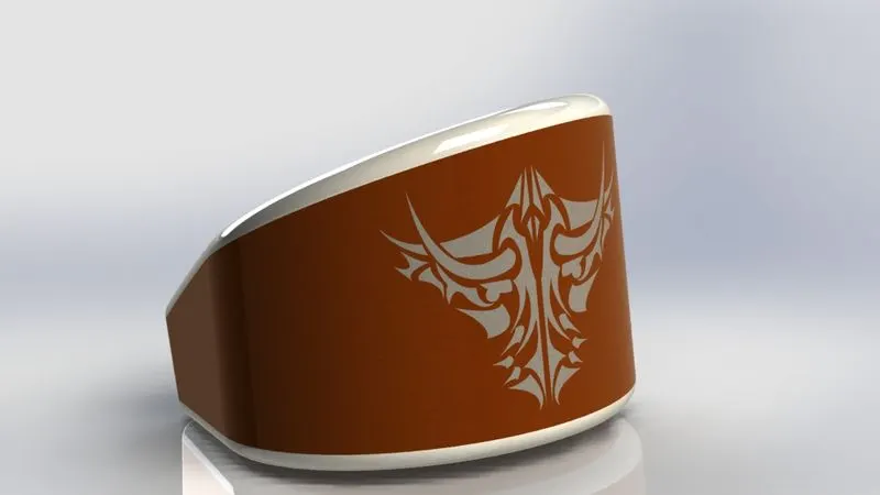
PROCEDURE
- Select top plane for sketch and draw appropriate geometry as per the blue print
- Extrude the sketch with extrude boss to attain the body of the oil tank
- Select mid plane and draw another sketch and then combine them both as one
- Apply fillet to all edge to get smooth finish
- The shell feature is added to the body which will remove all material to create hollow space inside
- Finally apply fillet to all edges with appropriate dimension and give appearance to the fillet as white and sienna to the body of the tank
7.CHAIN
Chain drive is a way of transmitting mechanical power from one place to another. Most often, the power is conveyed by a roller chain, known as the drive chain or transmission chain, passing over a sprocket gear, with the teeth of the gear meshing with the holes in the links of the chain.
COMMAND USED
Feature Tools: revolve boss, fillet, split, chamfer, combine, curved pattern, mirror
Sketch Tools: arc, line, construction line, slotted bar
Appearance -polished copper
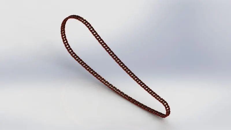
PROCEDURE
- Select the appropriate plane to draw to path of the chain with help of arc and spline
- Draw the front and back link for the chain as per the dimension and save them as block diagram
- Insert the blocks and give coincide and concentric relation to the block and the path
- Extrude the contours of the block to get the body of the front plate, back plate and pins
- Select the extruded body and apply curved pattern to get multiple body of the single link through the path
- Finally mirror the all parts with reference to the mid plane
- Finally apply the polished copper as the appearance for the chain link
8.FRONT WHEEL
It is a wheel designed for bike to support the front body of bike. In this spider webbed spokes are used. These spokes are connecting rods between rim and hub. The main work of spokes is to transfer the loads between rim and hub which causes due to weight of rider. The increasing wheel size will decrease the diving force from wheels which results in decrease in acceleration of wheels. It consists of rotor and calliper which is used to stop the vehicle
COMMAND USED
Feature Tools: revolve boss, fillet, split, chamfer, combine, curved pattern, mirror
Sketch Tools: arc, line, construction line, slotted bar
Appearance --tyre-matt rubber, (rim, rotor, calliper)-chrome plate
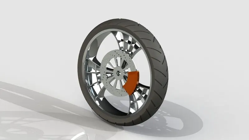
PROCEDURE
- Select the right plane for the sketch and draw the fully defined geometries like lines and arcs as per the dimension also apply sketch fillet to the edges
- Revolve the sketch with reference to the central axis to get the body of the rim
- Draw another sketch on the right plane for the spokes and extrude them as per the given dimension
- In front plane create a sketch for the spider web design using LINE, CIRCLE, TRIM, as per the dimension and extrude them with appropriate value
- To remove the excess material in the spokes, create a sketch on the right plane with given value and apply EXTRUDE CUT commend with the sketch
- Create sketch on the front plane with given dimension and extrude with an offset from plane for the rotor, also create sketch on the rotor to remove the excess material and apply extrude cut.
- Sketch on the rotor surface for the calliper with appropriate dimension and extrude the sketch.
- Finally apply appearances as follow tyre-matt rubber, rim-chrome plate, calliper-chrome plate and sienna paint.
9.REAR WHEEL
A wheel may be a circular block of a tough and sturdy material at whose centre has been bored a circular hole through that is placed Associate in Nursing shaft bearing concerning that the wheel rotates once an instant is applied by gravity or torsion to the wheel concerning its axis, thereby creating along with one in all the six straightforward machines. once placed vertically below a supporting platform or case, the wheel turning on the horizontal shaft makes it doable to move significant loads; once placed horizontally, the wheel turning on its vertical shaft makes it doable to regulate the spinning motion accustomed form materials (e.g. a potter's wheel); once mounted on a column connected to a rudder or a chassis mounted on different wheels, one will manage the direction of a vessel or vehicle (e.g. a ship's wheel or steering wheel) once connected to a crank or engine, a wheel will store, release, or transmit energy (e.g. the flywheel)
COMMAND USED
Feature Tools: revolve boss, fillet, split, chamfer, combine, curved pattern, mirror, extrude cut, revolve cut
Sketch Tools: 3-point arc, line, construction line, sketch fillet, trim, revolve, spline, mirror, rectangle, linear pattern, intersection entities, offset entities.
Appearance --tyre-matt rubber, (rim, rotor, calliper, sprocket)-chrome plate
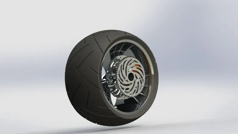
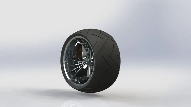
PROCEDURE
- Select the right plane for the sketch and draw the fully defined geometries like lines and arcs as per the dimension also apply sketch fillet to the edges
- Revolve the sketch with reference to the central axis to get the body of the rim
- Draw another sketch on the right plane for the spokes and extrude them as per the given dimension
- In front plane create a sketch for the spider web design using LINE, CIRCLE, TRIM, as per the dimension and extrude them with appropriate value
- To remove the excess material in the spokes, create a sketch on the right plane with given value and apply EXTRUDE CUT commend with the sketch
- Create sketch on the front plane with given dimension and extrude with an offset from plane for the rotor, also create sketch on the rotor to remove the excess material and apply extrude cut.
- Select the front plane and draw a sketch for the sprocket with appropriate dimension and extrude them with extrude boss and also apply extrude cut to remove material for teeth of the sprocket
- Sketch on the rotor surface for the calliper with appropriate dimension and extrude the sketch.
- Finally apply appearances as follow tyre-matt rubber, rim-chrome plate, calliper-chrome plate, sprocket-chrome plate and sienna paint
10.CHASSIS
A chassis is the load-bearing framework of an artificial object, which structurally supports the object in its construction and function. An example of a chassis is a vehicle frame, the underpart of a motor vehicle, on which the body is mounted; if the running gear such as wheels and transmission, and sometimes even the driver's seat, are included, then the assembly is described as a rolling chassis.it is also known as backbone of Bike.
COMMAND USED
Feature Tools: revolve boss, fillet, split, chamfer, combine, curved pattern, mirror , sketch picture, extrude cut, revolve cut, sweep cut, sweep extrude, projected curves , doom,
Sketch Tools: arc, line, construction line, spline, circle, offset entities
Appearance – Chrome plate
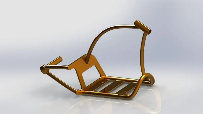
PROCEDURE
- First add the blue print sketch picture to the mid plane and adjust the picture to the appropriate position
- After that draw required geometries on the right plane and then extrude it. Now fillets are given to different edge, then using the Linear pattern tool make required number copy
- After that draw another sketch on the part that was previously created and is then extruded to connect the copies of the part. Then a sketch is drawn on the front plane that can be revolved to make the headlamp of the motorcycle.
- After that draw, a sketch on the part to make a small extrude for the light and fillet is given on the edges.
- Now to create the bulb-like shape to the light a dome is created on the extruded surface.
- Again, certain fillets are applied and then a sketch is created on the front plane to create a chamfer on the inside of the headlight.
- After then using the Body Move option the light is moved at a particular distance and angle.
- Then a curve is drawn using the spline tool on the front plane and another spline also. Then using the projected curve option, a resulting curve is obtained.
- After that, a circle is drawn on the handle joint and is used to create the handles of the chopper bike Sweeping through the projected curve from the circle.
- Now to create a plane a sketch is drawn on the end of the handle. Then a sketch is drawn on the newly created plane and is then revolved cut.
- After that, another sketch is made on the top plane that is revolved over the handle. Again, another plane is created on the handle to sketch the brake lever.
- After sketching it is extruded and the fillet is applied. Then by using the projected curves tool, the brake cable is created by drawing splines and a circle that is swept to form the cable.
- Now the whole part is mirrored about the face of the handle joint.
- Apply appearance to the body as chrome plate
11.FRONT FORK
The front fork prevents excessive weight on the front wheel during drastic sudden applications the break, softens bumping when driving on rough road surfaces. The front fork maintains proper damping through traction with the road surface.
The predominant type of front suspension is the suspension fork. It works like the front suspension on a motorcycle. ... When the fork moves up (when the bike hits a bump), the spring gets compressed and the piston forces fluid through the orifice.
COMMAND USED
Feature Tools: revolve boss, fillet, split, chamfer, combine, curved pattern, mirror, sketch picture, extrude cut, revolve cut, sweep cut, sweep extrude, projected curves, doom,
Sketch Tools: arc, line, construction line, spline, circle, offset entities
Appearance – Chrome plate, arial light, matt rubber
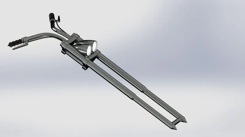
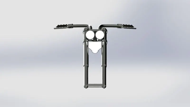
PROCEDURE
- The required plane is selected for drawing the sketch with appropriate dimensions. Then by using Revolve command select the required sketch to revolve and add material along its axis.
- Then at one edge required sketch is drawn and it is extruded to add material. The sharped edges are removed by using fillet option. By using Linear Pattern, the required part is selected at required position to form it again.
- At the one edge circle is drawn and extrude it to add material. To create head lights the required geometry is drawn on selected plane and revolve it around the axis.
- By using Swept Boss, the required path and circle is selected to follow circle along the path for required handle to be drawn. To form gripper at edge of handle the geometry with circles is drawn and revolve it along its base.
- To draw brakes required geometry with linear are drawn with appropriate dimensions then it is extruded to add material. Two circles are drawn at two different planes and by using spline thy are connected. The sweep is selected to follow circle along spline to form wire shape.
- By using Mirror, the whole body is selected and formed again along its side. The required Appearances are added for different parts.
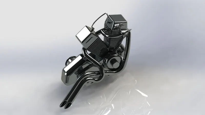
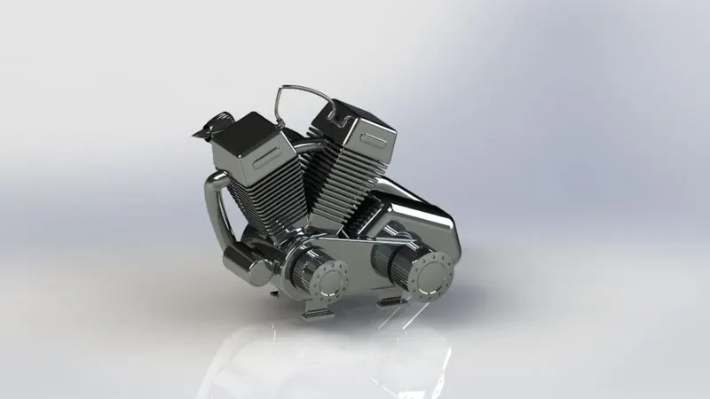
12.ENGINE
It is a machine used to change one form of energy into mechanical energy. It is a complex machine which is built to convert heat from burning gas into force for turning wheels. These energies can be in a form of petrol or diesel where chemicals are used to produce energy. The chain of reactions which achieve the objectives is set in motion by spark, which ignites a mixture of petrol vapor and compressed air inside a cylinder and causes it to burn rapidly. It contains a cylinder head contains valve-controlled passage through which air and fuel mixture enters the cylinder. So due to this the engine must be a robust structure.
This bike uses one of Dixie Chopper's 1000cc 32 horsepower (24 kW) Generac lawn mower engines which, after modification, provides enough power to be suitable for a motorcycle engine
COMMAND USED
Feature Tools: revolve boss, fillet, split, chamfer, combine, curved pattern, mirror, sketch picture, extrude cut, revolve cut, sweep cut, sweep extrude, projected curves, doom,
Sketch Tools: arc, line, construction line, spline, circle, offset entities
Appearance – Chrome plate
PROCEDURE
- Initially by using the blueprint the required sketch was drawn and extruded using Extruded Boss/Base and proper fillets were applied.
- Created plane by Reference Geometry and the transmission system were created for placing the Transmission belt. Then the fillets and dome were applied on the required area.
- Extruded Boss/Base were used and dome feature was used to create the dome on the either side of the cylinder, for creating the cylinders of the engine
- For creating the cooling fins Linear Pattern was used and the other half was mirrored along with the fins and domes.
- The Air Inlet Ducts were designed using Circular Pattern, Extruded Cut and Revolved Boss/Base.
- For creating the Exhaust Pipes Composite Curve feature were used on the reference plane which needs to be created on the face of the engine cylinder.
- By using Swept Boss/Base the exhaust pipes were created and finally Split option were used to cut the unwanted part.
- Then the Spark Plugs were made using Extruded Boss/Base and Swept Boss/Base.
- Finally, the part was saved by adding appropriate appearances
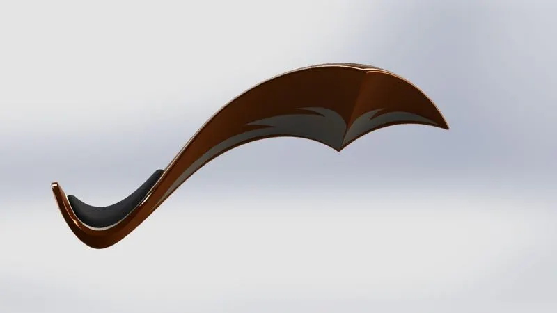
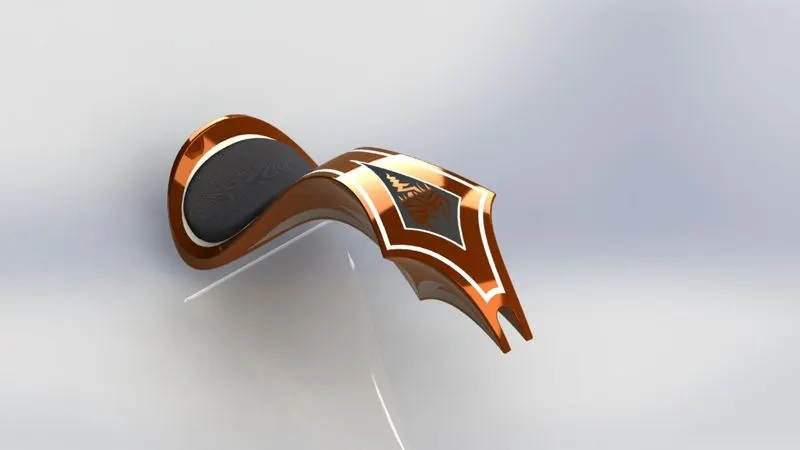
13.GAS TANK
A fuel tank/Gas tank is a secured compartment for combustible liquids. Despite the fact that any capacity tank for gas may also be purported, the period is for the most part used to a segment of a motor machine wherein the gas is saved and impelled or dispatched into a motor. Gas tanks differ in estimation and intricacy from the little plastic tank of a butane lighter to the multi-chambered cryogenic Space Shuttle outside tank.
COMMAND USED
Feature Tools: reference planes, mirror, sweep cut, shell
Sketch Tools: spline, line, sketch fillet, construction line, combine, sketch picture, convert entities, arc, trim, offset
Surface tool: sweep surface, trim, surface loft, projected curves, boundary surface, knit, split line, extrude surface, fillet
Appearance -white and sienna paint
PROCEDURE
- The required plane is selected for inserting image then sketch is created on plane by using required geometry. Splines are selected and adjusted for required design by giving dimensions to create Gas Tank.
- By using Reference Geometry some plane is created at some distance from one end of sketch. Then splines are created on this plane and some other geometry for reference. Swept surface is selected for creating surface along the required path.
- The unwanted surfaces are tried by using trim surface command. By using surface Loft required portion is added for creating surface. By using the plane which is created required sketch is drawn by applying proper dimensions.
- Above sketch is selected and project it by using projected Curve. Then end points are joined using lines by applying pierce by using boundary surface required space is selected to create surface over it.
- Then mirror is selected along midplane to form same part on other side of Gas Tank. Knit is selected to combine all the surfaces together.
- The seat is designed by selecting outer edges then offset is selected to form the same geometry. The arc is drawn by connecting both sides of geometry to form required shape.
- The above geometry is selected, and split line is applied to form on surface. Then Extrude surface is selected to add material. Fillet is applied to reduce sharp edges. The bottom portion of tank is added surface by using Boundary Surface.
- Some geometry is drawn on required plane then cut sweep is used to remove material. Then shell is applied to remove inside portion and make as thin material just like hollow part with required dimension.
ASSEMBLY
Combining multiple parts that fit together to create assemblies is called ASSEMBLY in SOLIDWORKS. We integrate the parts in an assembly using Mates, such as Concentric and Coincident. Mates define the allowable direction of movement of the components.
TYPES OF ASSEMBLY
- Top-down assembly
- Bottom-up assembly
Top-down assembly
In top-down assembly design, one or more features of a part are defined by something in an assembly, such as a layout sketch or the geometry of another part.
The design intent comes from the top, which is the assembly, and moves down to the parts. Examples of design intent include feature sizes, component placement in an assembly and proximity to other parts.
For example, you create a locating pin on a plastic part using the Extrude command. You choose the Up to Surface option and select the bottom of a circuit board, which is a different part. This selection makes the locating pin long enough to touch the board, even if the board moves in a future design change. The length of the pin is defined in the assembly, not by a static dimension in the part.
Bottom-up assembly
Bottom-up design is the traditional method. You first design and model parts, then insert them into an assembly and use mates to position the parts. To change the parts, you must edit them individually. These changes are then seen in the assembly.
Bottom-up design is the preferred technique for previously constructed, off-the-shelf parts, or standard components like hardware, pulleys, motors, etc. These parts do not change their shape and size based on your design unless you choose a different component.
Feature used for assembly
- Insert component
- Mates
- Mirror
Steps involved in the assembly
- Open all the parts of the chopper at once in solidworks
- Insert one by one in the assembly part and start giving appropriate relation
- After inserting the parts start giving the mates to get assembled in the appropriate manner
- Finally make sure all parts are fully defined with proper mates
Rendering
Rendering or image synthesis is the process of generating a photorealistic or non-photorealistic image from a 2D or 3D model by means of a computer program. The term "rendering" is also used to describe the process of calculating effects in a video editing program to produce the final video output.
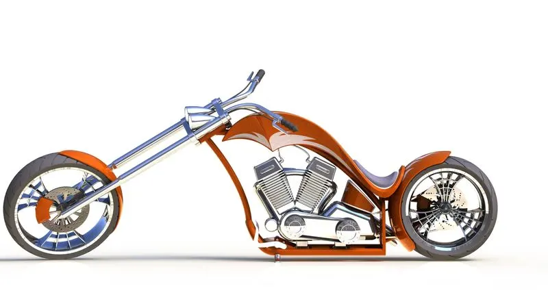
Rendering of American Chopper model is done by using PhotoView-360 and Solidworks Visualization.
PhotoView-360
PhotoView-360 is a visualization and rendering solution included with SOLIDWORKS Professional and SOLIDWORKS Premium. It Provides a highly interactive environment for viewing designs as well as for creating photo-realistic renderings that can be used to showcase our designs.
The PhotoView 360 software
PhotoView 360 is a software solution from Solidworks, fully integrated into the Solidworks software to create photorealistic images directly from Solidworks models. Renderings may be created from Solidworks parts and assemblies, but not drawings. PhotoView 360 can produce photorealistic images to add visual impact to presentations and documents.
Some of the key features of PhotoView 360 are:
- Photorealistic images directly from Solidworks models
- PhotoView 360 interacts with the 3D geometry created with the Solidworks software. All changes to Solidworks models are accurately represented in the PhotoView 360 images.
- Fully integrated into Solidworks.
- PhotoView 360 software is supplied as a Solidworks add-in.
PHOTOVIEW 360 RENDERED IMAGE
ISOMETRIC VIEW
RIGHT VIEW
SOLIDWORKS Visualize
Quickly and easily create professional, photo-quality images, animations, and other interactive 3D content to get your products to market faster.
SOLIDWORKS Visualize allows us to leverage our 3D CAD data to create photo-quality content in the fastest and easiest way we can–from images to animations, interactive web content, and immersive Virtual Reality. It brings our products to life. SOLIDWORKS Visualize is the “camera” for our CAD data.
Some renderers are fast but output low-quality images. Some produce great quality but take six months to learn. Others are easy to use, but take four hours to render an image. SOLIDWORKS Visualize provides the right combination of quality, speed, and ease of use, and is the best renderer.
SOLIDWORKS VISUALIZE PROFESSIONAL
With SOLIDWORKS Visualize Professional we can tell a deeper 3D story about our product using our CAD data. It enables us to easily generate photo-quality stills and interactive animations to effectively communicate the most complex design details.
The features of SOLIDWORKS Visualize Professional are listed below,
o Demonstrate products more effectively with full animation of parts, models, appearances, cameras, and environments
o Import our SOLIDWORKS CAD Motion Studies for truly photographic animations
o Quickly show off the final design with one-click 360-degree spins
o Create interactive web content such as Interior Panoramas and Exterior VRs
o Present and compare varying design solutions side-by-side with multiple viewports and included Configurator tool
o Unleash our creative side with customizable Camera Filters
SOLIDWORKS Visualize Professional also includes key features to help increase productivity. The integrated Render Queue allows us to stack up jobs on our machine or a dedicated render farm to automatically complete one after the other, providing remarkable time savings.
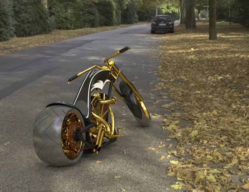
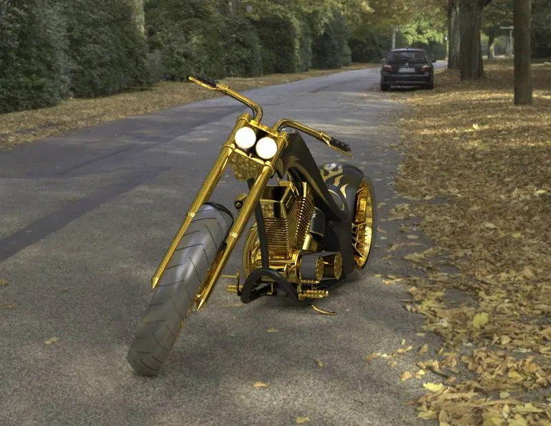
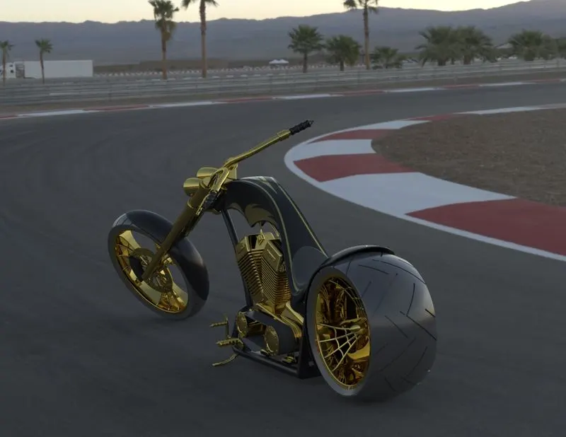
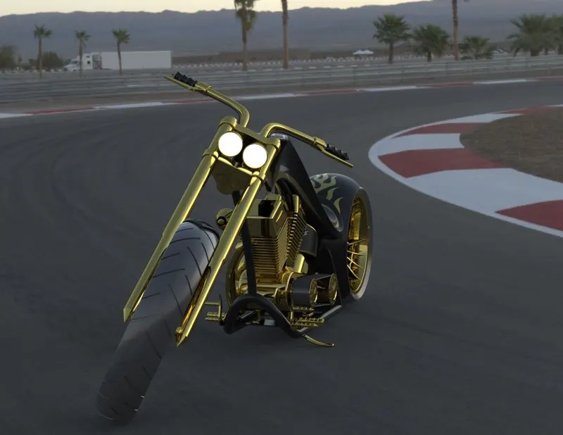
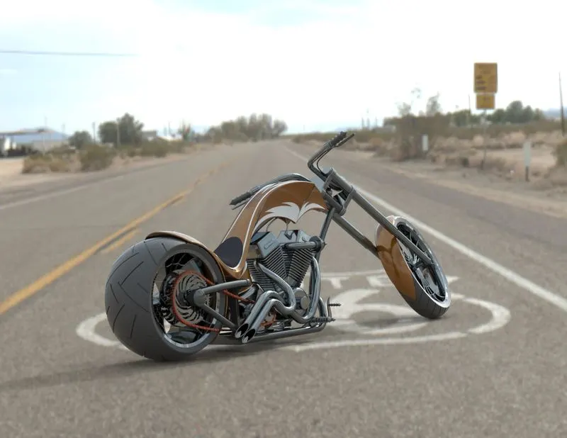
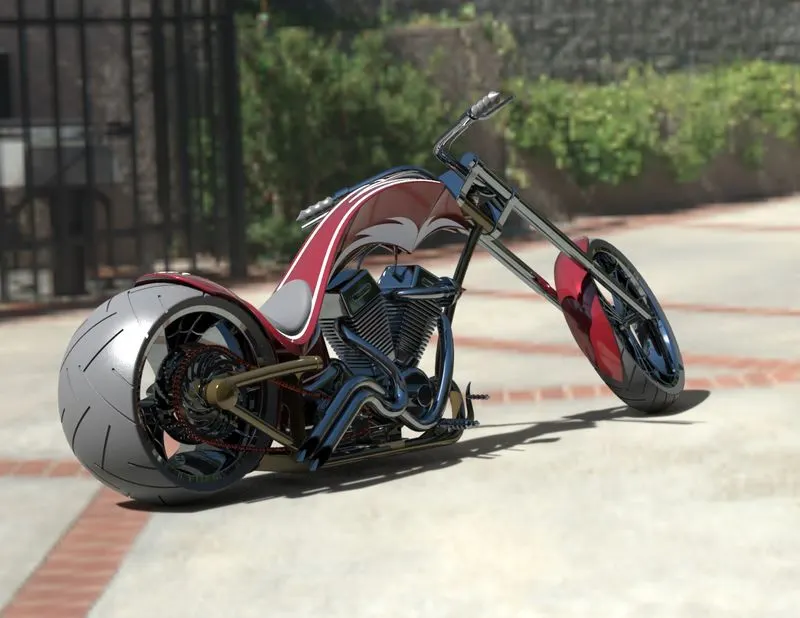
PHOTO-REALISTC IMAGE OF THE OF THE CHOPPER
VISUALIZED IN THE FALL STREET
VISUALIZED IN THE RACE TRACK
VISUALIZED IN THE HIGHWAY (route 66)
VISUALIZED IN STREET
CONCLUSION
Thus, the 3d-cad modelling of an American chopper with SOLIDWORKS 2021 and photo-realistic rendering using PHOTOVIEW 360 and SOLIDWORKS VISUALIZE has been successfully completed