BIW COMPONENT- FRONT FENDER DESIGN
BIW COMPONENT- FRONT FENDER DESIGN
OBJECTIVE
The main objective of this project is to design the BIW of a Fender using the fender skin data as the input data and then create mountings on the fender for attaching it with the surrounding BIW bodies.
Introduction:
Fender is the American English term for the part of an automobile, motorcycle or other vehicle body that frames a wheel well. Its primary purpose is to prevent sand, mud, rocks, liquids, and other road spray from being thrown into the air by the rotating tire. Fenders are typically rigid and can be damaged by contact with the road surface.
Sticky materials, such as mud, may adhere to the smooth outer tire surface, while smooth loose objects, such as stones, can become temporarily embedded in the tread grooves as the tire rolls over the ground. These materials can be ejected from the surface of the tire at high velocity as the tire imparts kinetic energy to the attached objects. For a vehicle moving forward, the top of the tire is rotating upward and forward, and can throw Objects into the air at other vehicles or pedestrians in front of the vehicle. Fender is a front outer side member of a car, which covers the wheel side. It has so many small features with ups and downs.
The Importance of Car Fenders:
-
Fenders are an intricate sheet of metal covering the wheel well of your car.
-
Fenders are designed in a manner to provide resistance against wind and other roadside debris.
-
When you travel on rough terrains your vehicle might get minor scratches and dents which look no better. Frequent road bumps can cause your cars paint to chip off which needs a paint job done.
-
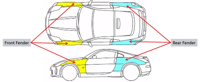
The car fenders are located on either side of the front and rear wheels. The front car fenders begin where the front door hinges run and end just before the bumper. The rear car fenders begin where the back doors close and terminate before the back bumpers.
TYPES OF CAR FENDERS:
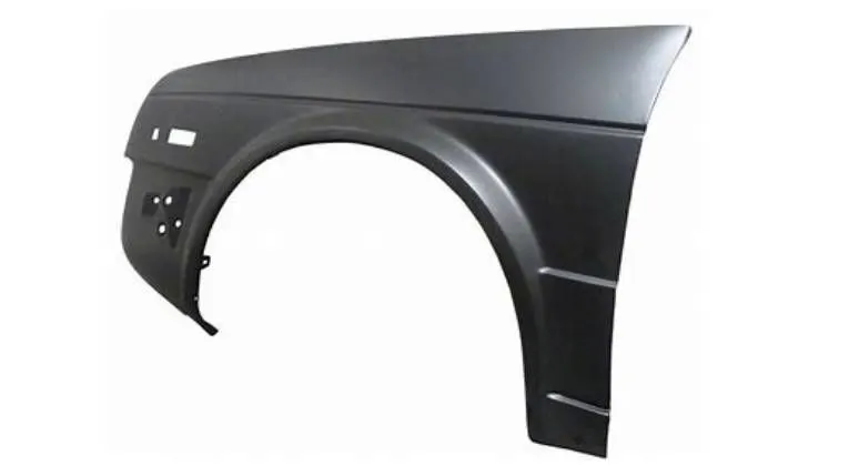
The type of fender is based upon the area covered i.e., full fender type and half fender type.
1. Full fender type:
Full fender type is traditional type of fender where more material consumption is observed. This type is used in old design of automobiles where it increases the overall weight and thus reduces performance.This type of bumper is not commonly used because this design is more scrap producing one during manufacturing. The blank of steel or aluminum used to produce this type has more wastage. This type is not economically good to manufacture. Also it increases the material cost unavoidably. If we use full bumper type the material has to be either aluminum or steel, since these materials were generally used for fenders. This extension of material usage in bumpers might increase the proportion of weight and consequently reduce the performance of vehicle. Nowadays plastic material components are in use for bumper making. Plastics have high tendency in absorbing the shock and impact loads. And being light in weight it is easy to mount them on chassis.
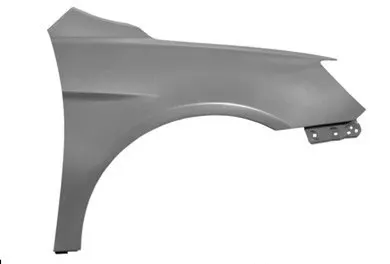
2.Half fender type:
Half fender type is modern design where less material consumption is observed, so productivity increases by reducing size of blank and thus providing more performance. The maintenance also relatively low compared to full bumper type.The maintenance also relatively more due to more surface.This is the most commonly used typed of fender. The con’s of full bumper type is satisfied in this design, and the blank area of wastage while producing the part is drastically reduced by scrap management. In this type by slightly increasing the blank size 50% of wastage is reduced by making two fenders on a same single blank of steel or aluminum. Also this design provides space for using plastic components in the bumper. Thus facilitating way for reducing a high proportion of weight and increase the vehicle’s performances significantly.
Purpose of fender:
- Cleanliness-Protect the car, occupants and passersby from items, water, mud, snow, ice, thrown off the tires as you drive.
- Safety-Protects pedestrians from the wheel, e.g. its better to be it by a laterally moving fender than a rolling tire, keeps loose, streaming items from being wrapped up in a rolling wheel.
- Aerodynamics-Smooths the car profile so you don't get a lot of drag off the uncovered wheels. Some fenders are enclosed on the side for this.
- General appearance-Looks better with fenders, gives a finished look, looks more streamlined.
Material used in Fender Design:
You can find modern fenders made from steel, aluminum, thermoplastic, and fiberglass. Steel is the most rigid and abrasion-resistant material used in making fenders. They offer the best protection from large debris and are less likely to dent. Aluminum offers the strength of metal without the heaviness of steel.
Front Fender Design
As per the data given from the styling team the required mounting area as to be designe. In order to fix the front fender in the car it requires minimum of 4-5 mounting area they are classified as, A Pillar Mounting, Bumper Mounting, Drip Area mounting, Baffel Mounting, Sill Mounting. Only for Drip area mounting the skink data is given for rest of the mounting like Sill mount, Bumper Mount and A-Pillar mount as to be design on own according to the Engineering standard that I learned in the class.
MASTER SECTION AND SKIN DATA:
Design Criteria:
-
Embosses are provided to increase the strength.
-
Smooth curves are designed for easy manufacturing of panel.
-
Ribs are provided to drip area mount to give structural support and extra strength.
-
Maintain extra 10 mm from the flat surface for the fastner holes.
-
All fillets should maintain 3 + thickness mm radius in most regions.
-
Thickness of fender is 0.75 mm.
1. A Pillar Mounting
Here this region is mounted to the A-pillar frame of the chasis so that it is rigidly attached to the body of the car. A car has many pillars according to the design and the style of it. It is the number of vertical portions in a car. In a sedan type of car, there will be three pillars. If it is a hatchback model, then it has four pillars. The front most pillar is called as A- pillar. This mounting is assembled with A-pillar of the car.
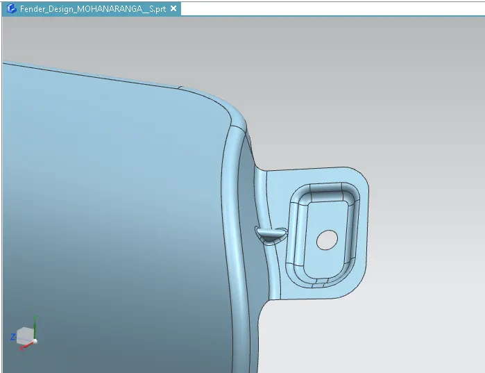
PROCEDURE
- First the skin data provided by the styling team needs to be extracted.
- outer edge of the fender was offset inwards to particular length.
- Using the curve on surface command the unwanted portion were trimmed out using trim sheet.
- By using the law extension, the A pillar were extended and trimmed on the sides to get a flat edge.
- For creating a flat emboss which was used to mount the fender with the A-pillar a datum plane was created.
- Then the required sketch was drawn on the datum plane and projected to the surface.
- To create a fastener hole which needs to be around 5 mm gap around it trim surface command were used.
- Atlast the required blends were added using face blend and edge blend.
2. Drip Area mounting
This region is mounted below the hood inner panel which needs to be in flush when the hood is in closed condition and also there should be very less gaps.The drip area is either spot welded or in some cases bolted down via self-tapping screws.
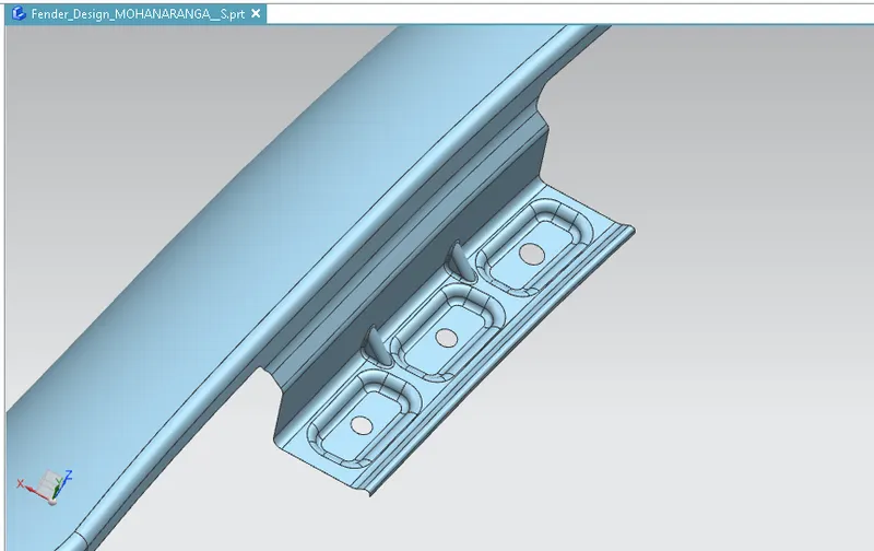
PROCEDURE
- By using the information in the master section provided the drip mounting were created.
- The drip area must be minimum 150 mm apart from the front edge so that the drip mounting won’t disturb the head lamp mountings.
- From backwards the drip area must be 200 mm apart from back edge to avoid the coincidence with the engine cables.
- The flange for the dirp area mounting is extracted as Considering the fornt and back clearance.
- The emboss and dart is provided to strengthen the mounting area and to avoid the NVH.
- Then for creating the fastener holes the trim sheet options were used.
- Then the required blends were created for improving the aesthetic of the fender.
4. Baffel Mounting
This area is to make the holding of stronger. This is to provide uniform holding all over the fender. Even the plastic part can be fixed in this region for lining part mounting.
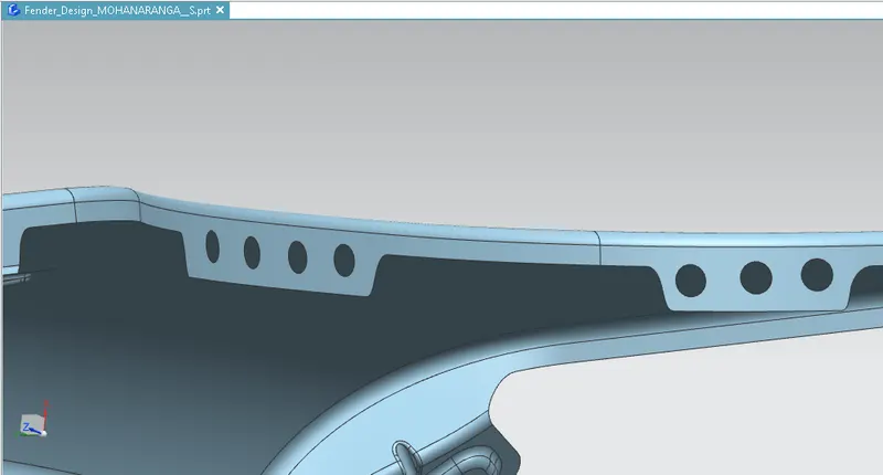
PROCEDURE
- The baffle mounting was designed to fit a splash mounting on it which helps the engine compartment to protect it from the debris that entering in to while driving.
- For creating it three mounting areas were created with the required holes on it for the fasteners.
- For creating the holes, a datum plane was created on all three mountings and projected on to the surface.
- By selecting the required vector and deselecting the project on both side option the holes were created.
5. Sill Mounting
Sill mount is a portion fixed to the door sill. Sill is a part of car frame at the bottom.
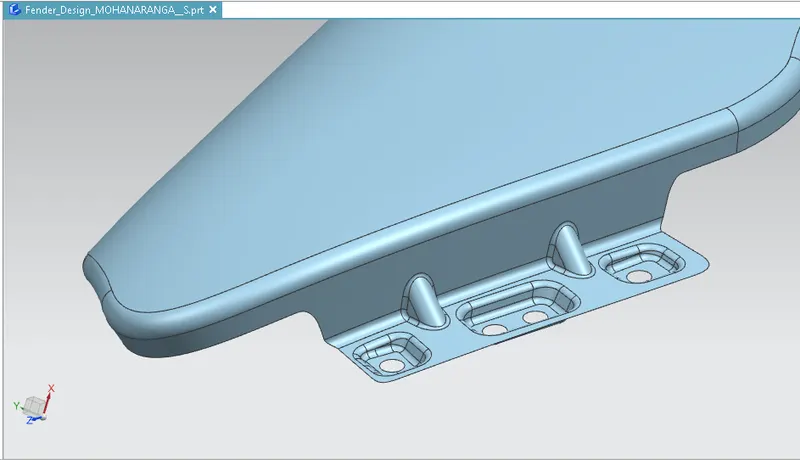
PROCEDURE
- For creating the sill mounting the extra portions were trimmed out.
- Then the datum was created and the required sketch was drawn and then projected.
- Then emboss were generated and blended the edges together.
- The fastener holes were created by using the trim surface feature.
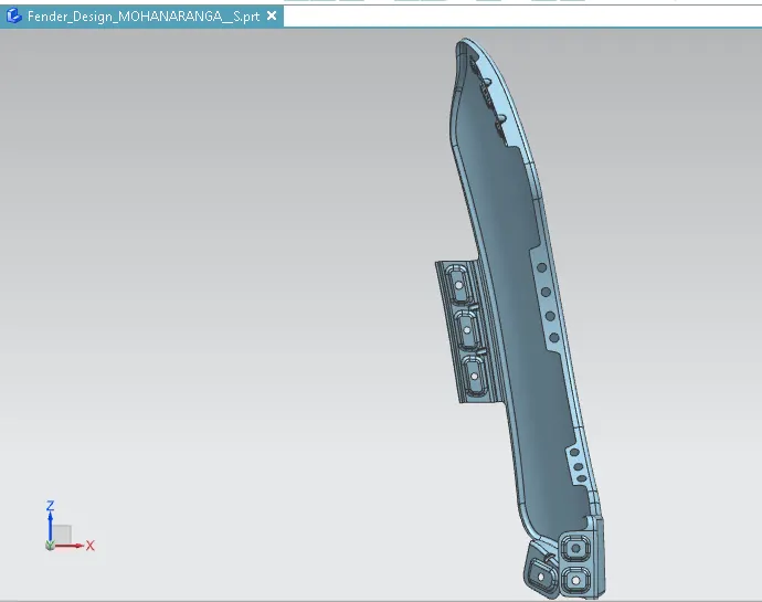
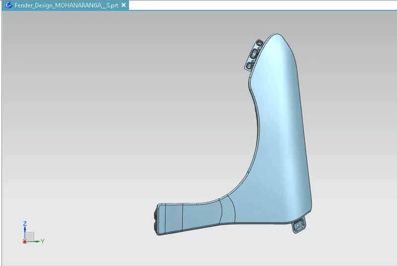
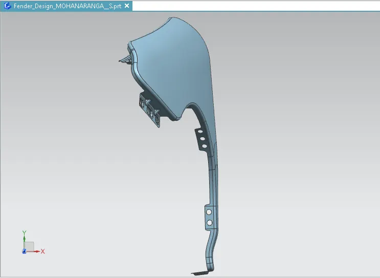
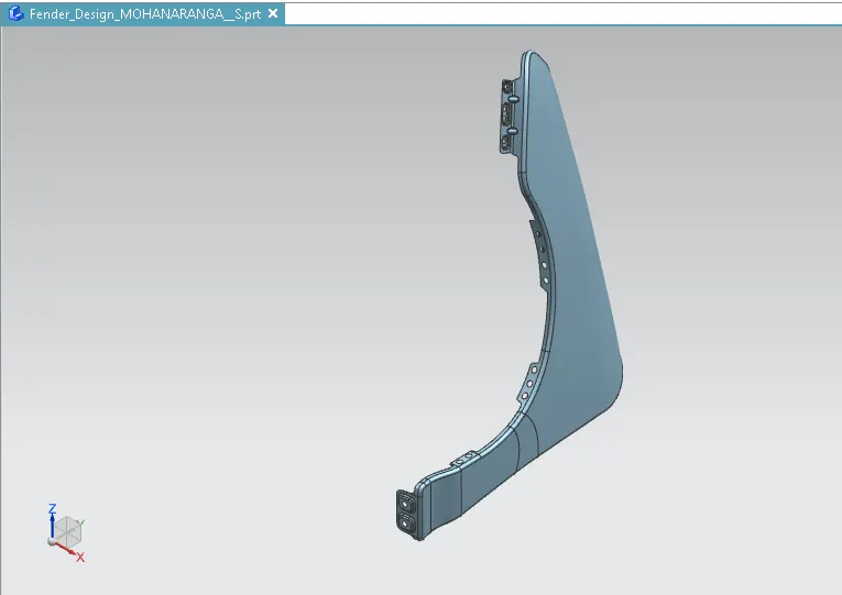
DIFFERENT VIEWS OF FENDER
FRONT VIEW
SIDE VIEW
TOP VIEW
ISOMETRIC VIEW
CONCLUSION:
Thus the mountings of the front fender has successfully designed as per the rules and requirements. The drip area is designed as mentioned in the master design and other parts are designed with own idea with proper dimensions and engineering standards.