SHEET METAL BOX ASSEMBLY Design Using NX Cad Challenge_2_Box Assembly
CAD MODELLING OF AN SHEET METAL BOX ASSEMBLY USING SIEMENS NX_CAD.12
OBJECTIVE
The purpose of this project is to design an aesthetic CAD model of sheet metal BOX_ASSEMBLY using siemens NX_CAD sheetmatal application workbench.Also to perform the drafting for the casing part.
INTRODUCTION
The sheet metal parts can be found from the small light fixtures to the automotive body parts because of their high strength despite having low weight and its resistance to corrosion. Based on the requirements and the standards sheet metals of varying thickness are used. The sheet metal comes from various materials such as steel, aluminium, brass, titanium and more. sheet metal application provides an the envinornment for the design of the sheet metal part in machinery, automotive, enclosures, brackets and other parts normally manufactured with a barke press
Sheet metal application widely used in
- Aircraft Bodies
- Automobiles
- Utensils used for domestic purpose
- Beverage cans
SOFTWARE USED
- SEIMENS NX_CAD
Unigraphics NX (also known as Siemens nx) is an advanced High-end CAD/CAM/CAE software package originally developed by UGS Corporation, But since 2007 it is owned by Siemens PLM Software. It is used, among other tasks, for Design ,Engineering analysis ,Manufacturing finished design by using included machining modules
DESIGN METHODOLOGY
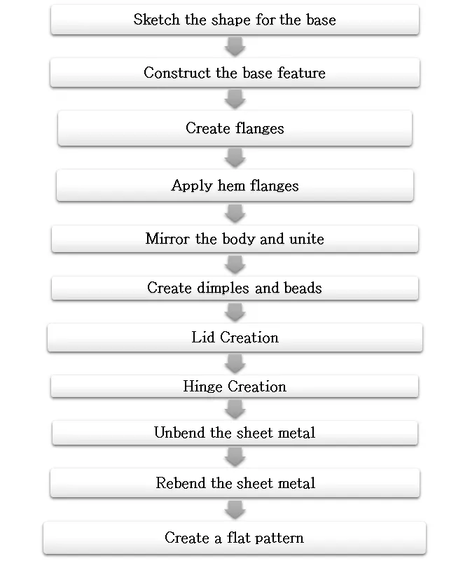
The design methodology used for this projet is summarized in the below flow chart.
Tab:
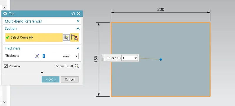
The tab is the very first feature in any sheet metal component design process. All the other features of the sheet metal in Siemens NX are based on the base feature or tab. A tab is created after a sketch is created in any of the planes or datum plane created. The tab is always the parent feature for other features following it.
Flange:
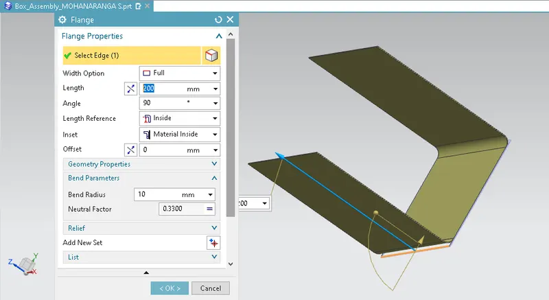
The flange is an additional face created from any edge of the existing sheet metal component. It is additional material connected to any face or edge which is bent from the respective edge or face. It can be at any position or at any angle.
Closed Corner:
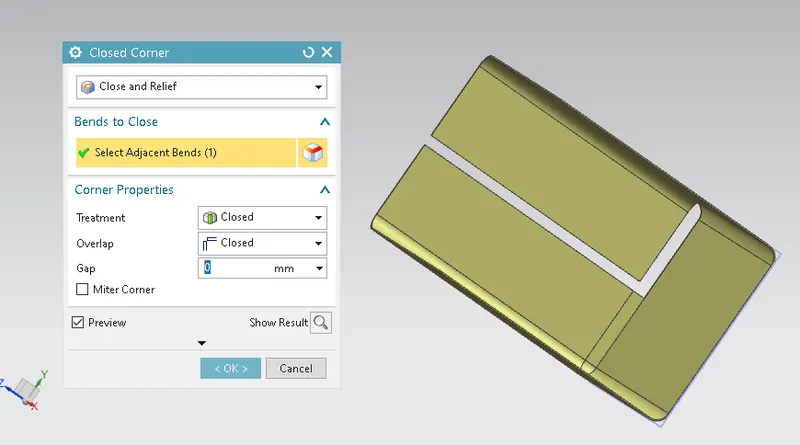
This tool closes the opening between two flanges or between the tab and flange which are perpendicular or at any angle. It should be adjacent to be able to apply the feature.
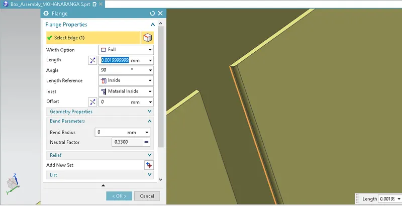
Flange for fastening:
For the fastening purpose by the bending of edges, a flange without length is first made and another bend flange is used to bend it outwards to obtain the following result.
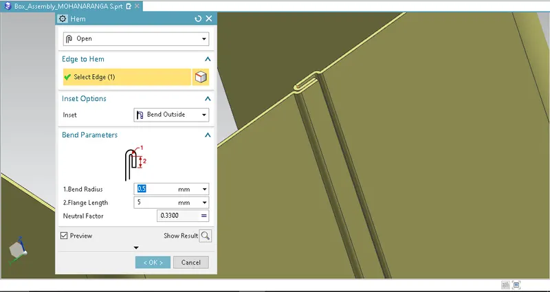
Hem Flange:
Hem Flange is the feature in sheet metal parts which bends the open edges at the end and prevent the sharpness of the sheet metal from any possible accidents. Also, it increases the strength and stiffness of the sheet metal part
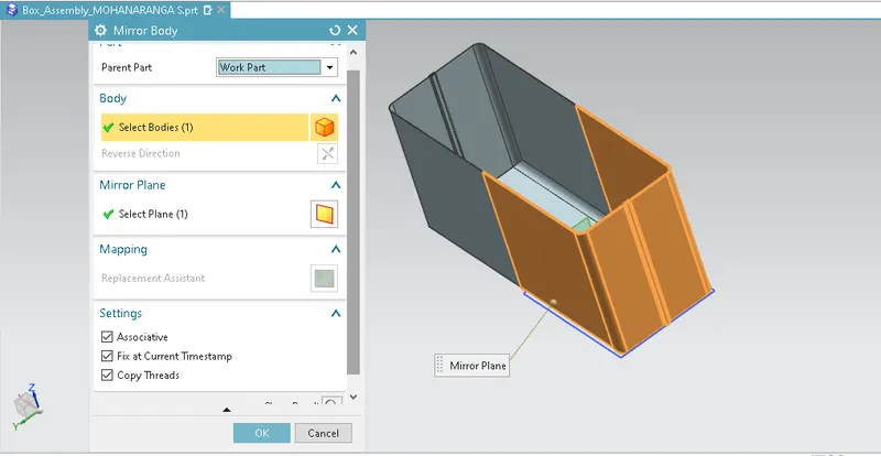
Mirror Body:
Mirror body feature allows the solid body to get copied and mirrored with respect to a plane. Here, the design made till this stage is a half part of the box which is then mirrored with respect to YZ plane.
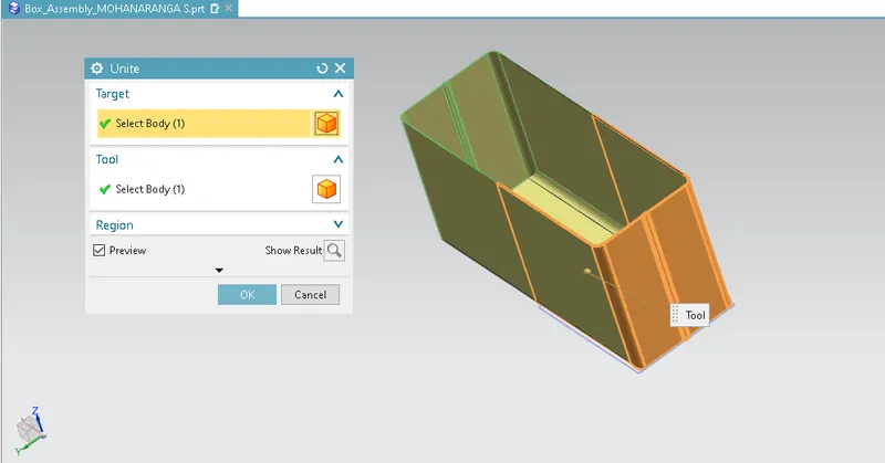
Unite:
After the mirror of the body is completed, it results in two separate bodies which is not the intended one. Unite allows us to combine the bodies and make one single body. After applying the Unite feature, the black edge on the face disappears.
Dimple:
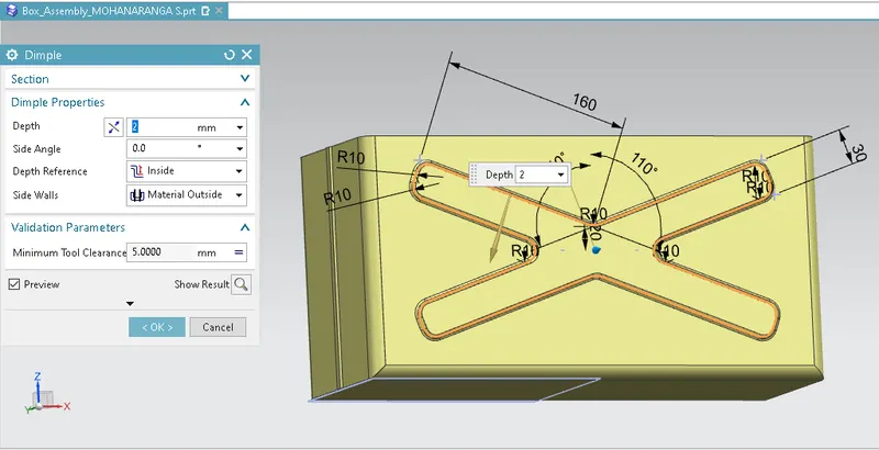
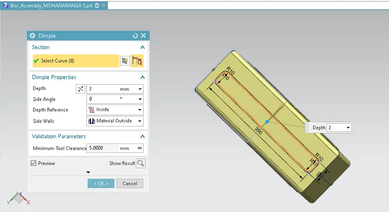
Dimples in sheet metal components provide more strength and rigidity to the flat structure of the component. Dimple feature in Siemens NX is created using the sketch created in any face or any flange of the sheet metal component.
Beads:
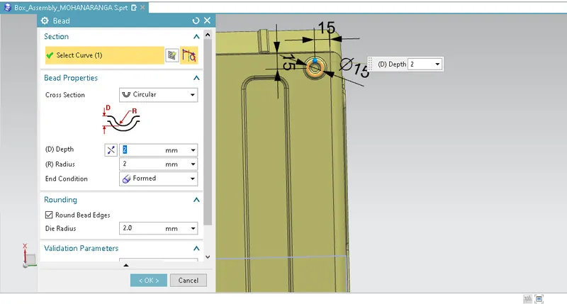
Beads are the features added in sheet metal components in order to increase the stiffness of the component. Beads require a sketch in order to apply the feature. It can be either an open or closed profile.
Hem Flange:
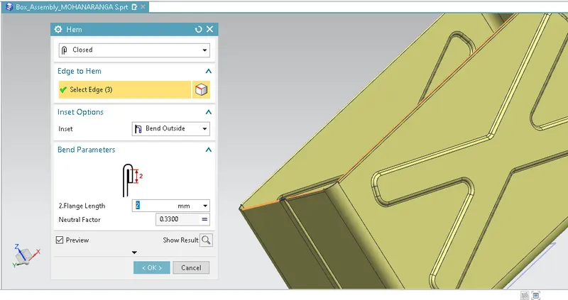
At this stage, the hem flange is applied at the top edge of the side flanges, and the flanges normal to the YZ plane.
Datum plane:
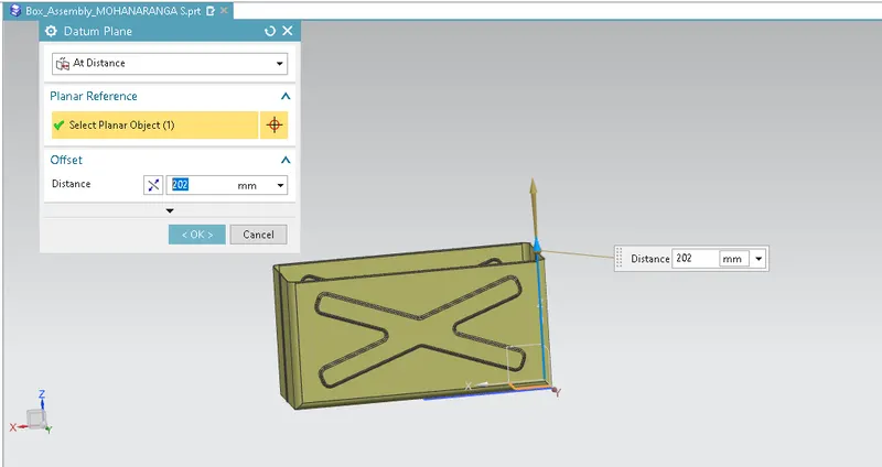
To create the lid for the box, a datum plane is created at a distance of 202 mm from the XY plane. The sketch is created taking the reference of the edges from the top view of the box design at this stage. Then the base tab is created with the sketch to create the lid. It will be a separate body in the box assembly design.
Flange:
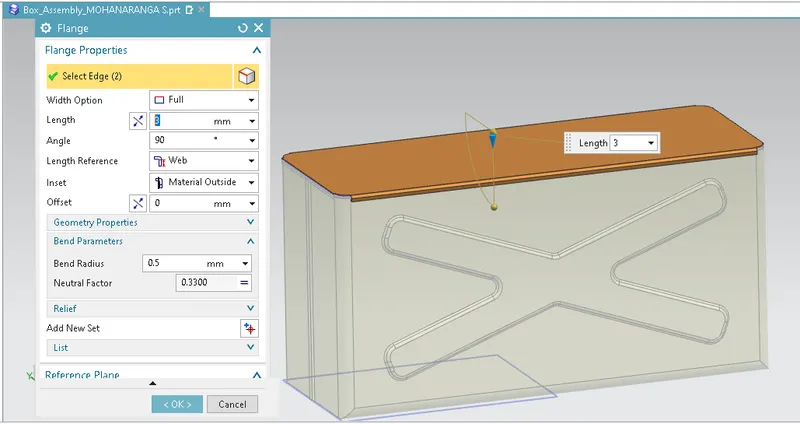
A flange of 3 mm web length is added on both sides of the lid which allows it to close the box with proper alignment.
Tab for hinge:
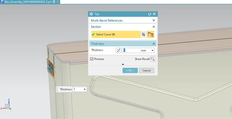
A datum plane is created on the face of the flange perpendicular to the YZ plane and a rectangle is sketched to create a base tab.
Break Corner:
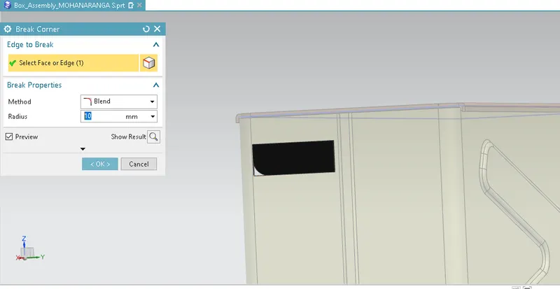
This feature breaks the sharp edges in the corners and makes it round or adds chamfer. It is like the fillet feature in some other CAD software. It prevents the fracture breaking of the sharp corners.
Flanges:
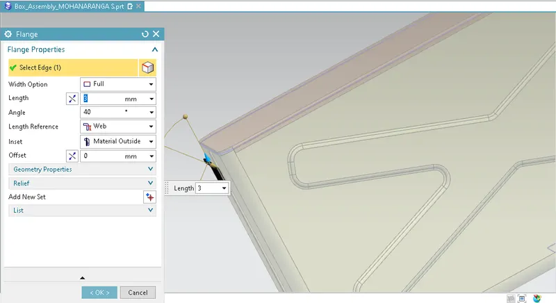
Now, two flanges of 40 degrees bend each of length 4 mm is created adjacent to each other to get the following result.
Hem Flange:
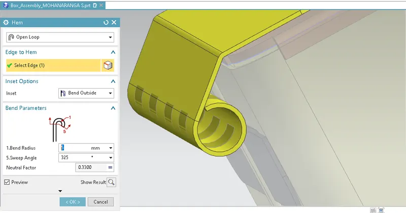
An open hem flange of radius 5 mm and angle of 325 degrees is added at the end of the flange to create the hinge for the box lid.
Normal Cut-out:
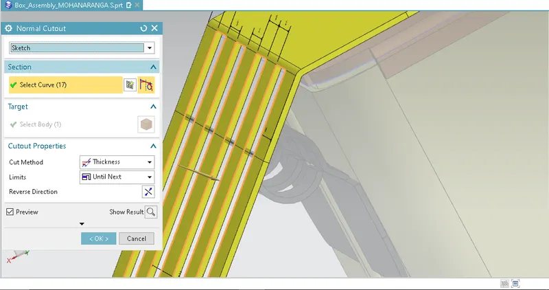
The unbend feature is used and the sketch is created on the face of the hem flange in the flat stage. Two rectangles are created as per the requirement for the hinge barrels of both sides. Then the operation normal cut out is carried out.
Flat Pattern:
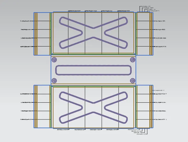
Flat pattern is the representation of the entire sheet metal component in the 2D form of the flat sheet metal with all the bends, cut-outs, holes, and additional features in the form of lines or edges. The flat pattern ensures the ability to cut the sheet metal out of the raw sheet metal plate. It removes the possible errors such as interference or collision within the same component.
Drafting:
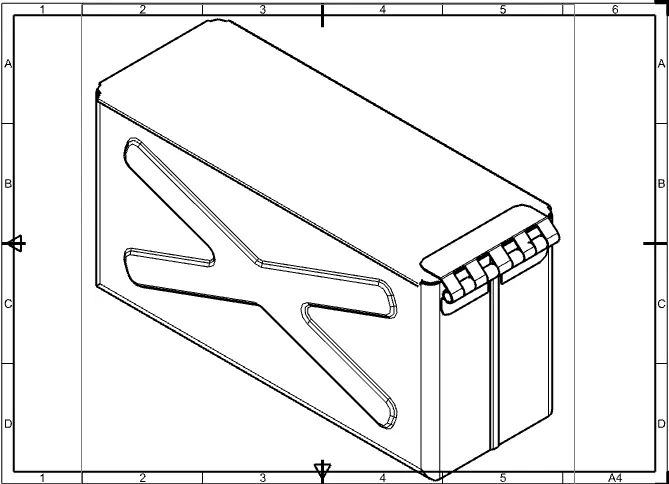
After the design is complete, the execution or the manufacturing of the component requires a technical drawing of the component with the provided scale and with accuracy. The necessary details such as annotations, callouts, bend tables can be added as per the requirement. For this box assembly design project, a drawing is created out of the flat pattern in a 5:1 scale in the A4 sheet with an additional drawing of a 2:1 scale.

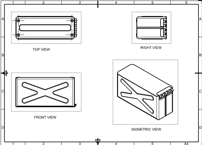
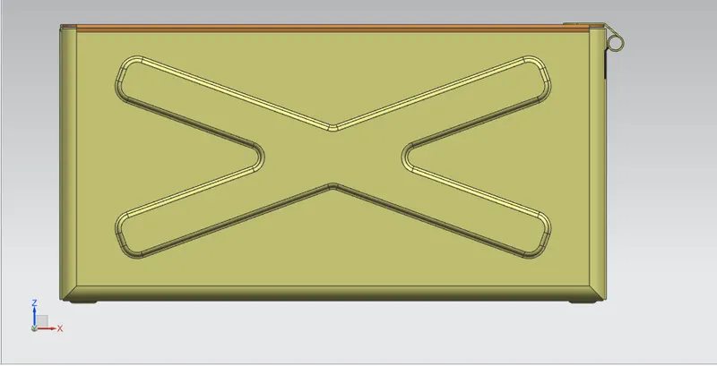
FRONT VIEW
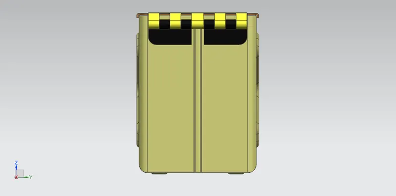
RIGHT VIEW
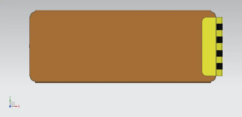
TOP VIEW
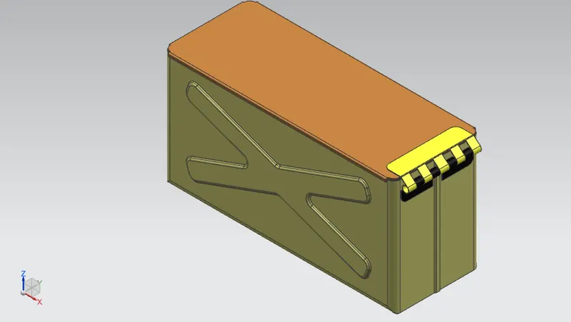
ISOMETRIC VIEW
CONCLUSION
Thus the sheet metal box assembly is successfully designed and drafted using SIEMENS NX_CAD and all the required feature are applied in order following the industrial workflow.