Week 9 - Attachment Feature Creation - Challenge 1
Aim:
Create the rib for the Centre console coin holder considering the standard design rules.
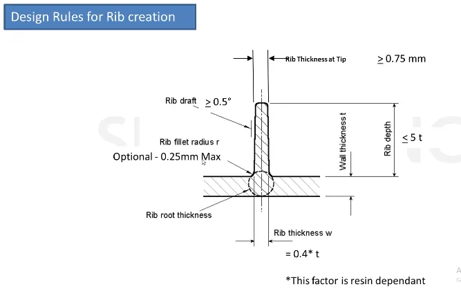
Introduction:
Rib: Ribs are thin, wall-like features typically designed into the geometry of a part to add internal support to walls or other features like bosses. In a similar fashion, gussets are support features that reinforce areas such as walls or bosses to the floor.
Ribs provide a means to economical stiffness and strength in molded parts without increasing overall wall thickness. They also facilitate:
1) Locating & arresting components of an assembly.
2) Providing alignment in mating parts.
3) Acting as stops or guides for mechanisms.
A well-designed rib will overcome the following disadvantages:
1) Increase part weight and cost proportional to the increase in thickness.
2) Increase molding cycle time required to cool the larger mass of material.
3) Increase the probability of sink marks.
Typical uses of Ribs:
1) Covers, cabinets and body components with long, wide surfaces that must have good appearance with low weight.
2) Rollers and guides for paper handling, where the surface must be cylindrical.
3) Gear bodies, where the design calls for wide bearing surfaces on the center shaft and on the gear teeth.
4) Frames and supports.
Ribs design involves 5 main issues:
1) Thickness.
2) Height.
3) Location.
4) Quantity.
5) Manufacturability.
1) Rib Thickness
Ribs should be designed to be 50-60 percent of the nominal wall thickness. Thinner does not provide much structure and may be hard to fill. Thicker ribs are tempting, but they can begin to introduce sinks on the cosmetic surface.
Bottom Rib Thickness : ( 0.3 to 0.6) * Wall Thickness
Note: Top Rib Thickness should be minimum of 0.75mm.
2) Rib height
For maximum effectiveness, rib height should be no more than three times the nominal wall thickness. Since the rib will be thinner than the wall, it may be hard to fill it if it is taller.
Rib Height= (3 to 5) * Wall Thickness.
3) Rib spacing
Increase the number of ribs rather than their height in order to increase stiffness. Ribs should be spaced a minimum of two times the nominal wall thickness apart from one another.
Rib Height/Rib width ratio = 3:1 –steel.
Rib Height/Rib width ratio = 2:1 –preferred
4) Rib draft
A minimum 0.5-degree draft will ensure that they release from the tool during molding.
Rib draft = (0.5 to 1) degree.
5) Rib coring
Core thick ribs from the back or below to create a blank area and thinner rib walls. This will help mitigate cosmetic sinks.
6) Rib fillet
Fillet at feature intersections to increase rib strength.
Rib fillet = 0.125 * Wall Thickness.
7) Rib Root Thickness
It is the thickness at the intersection of Rib and Wall of the plastic component.
Rib Root Thickness = (0.3 to 0.5) * Wall Thickness
Creation of Rib for the Centre console coin holder
Software Used: CATIA v5
Procedure:
- To create a rib first, extract the base surface of the coin holder.
- Create a positioning sketch, draw a line, constraint it and define it as an output feature.
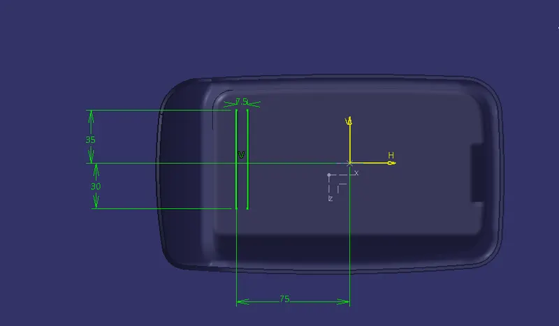
- Extrude the output line using extrude command.
- Goto Part design, create a part body and assign thickness to the extruded line.
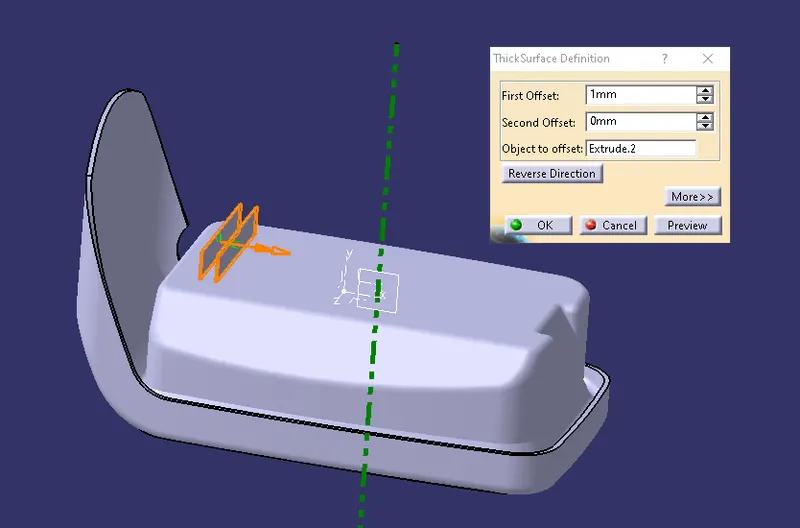
- Draft the thickened rib with an angle of 0.5 deg.
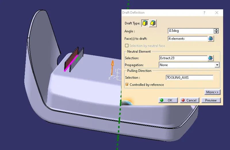
- After drafting, measure that the top surface is greater than 0.75mm and give the fillets to the edges of 0.25mm all sides.
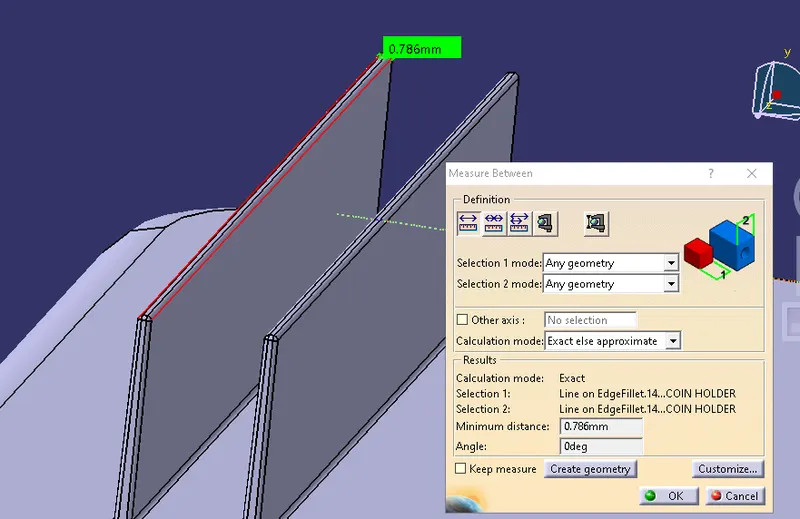
- Assemble the rib body with the coin holder.
- Similarly, create another rib with a distance of 2:1 ratio from the created rib.
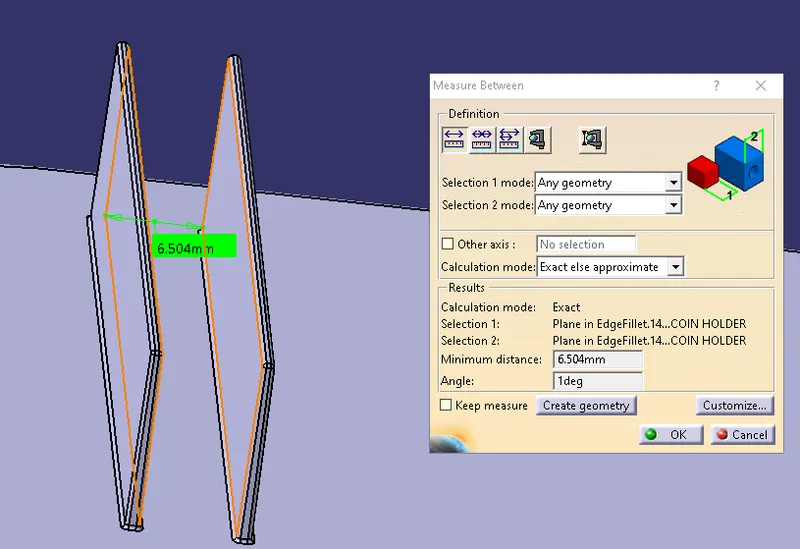
Creation of Tooling axis
Procedure
Step-1: Continuity check on class-A surface of Coin Holder
Initially for any class-A surface , first step is to check wheather the surface has continuity without any breaks and disjoints in it.
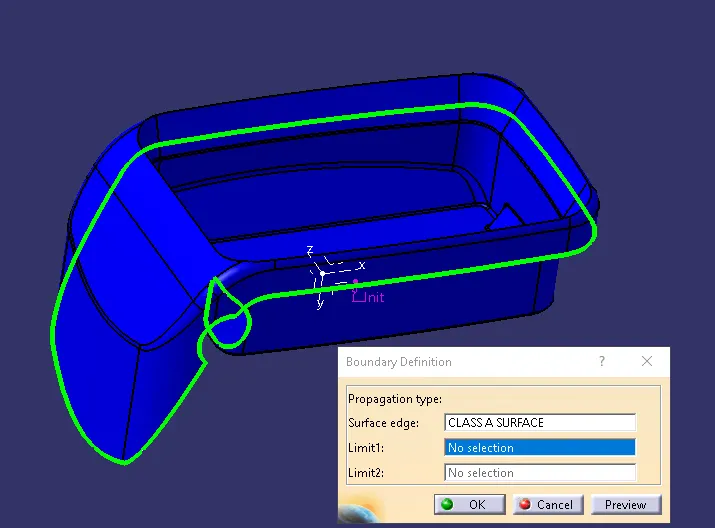
STEP-2
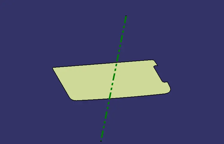
Extract the base surface of the given Class- A Surface and create the center point of the Extracted surface.
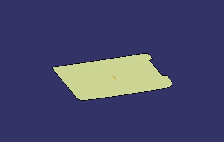
STEP-3
Then the tooling axis created using line commend which is normal to the extracted surface.
Performing Draft analysis on the Centre console coin holder
Procedure for draft analysis on solid Body
Step-1- Choose the Feature Draft Analysis command from the Analysis toolbar marked in red box.
Insert-> Analysis-> Draft analysis
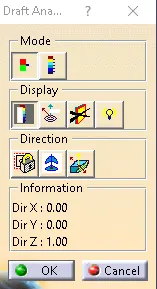
Step-2- Enable the compass feature in the Draft Analysis Toolbar as shown below.
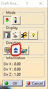
Step-3- Place the compass on the required position and along the desired tooling direction on the part
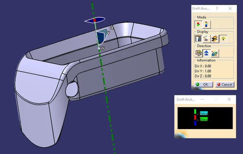
Step-4- Select the part on which draft analysis has to be performed. The part turns to the combination of colors present in the scale
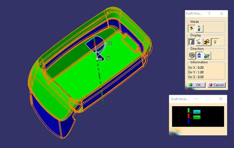
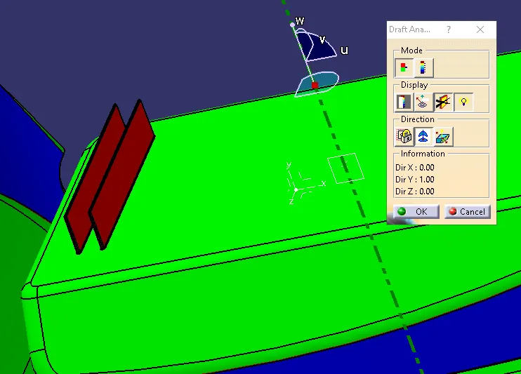
Step-5- Analyse the part with respect to the results obtained based on the scale, to identify the parts with draft feature. Quick analysis mode was chosen for the analysis.
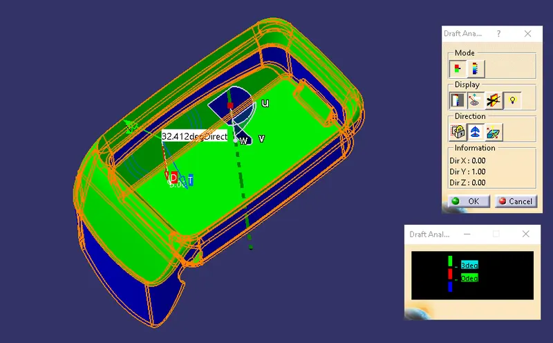
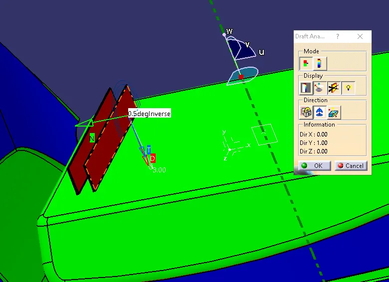
The above image shows the result on min of 3deg draft angle. Since the required draft value is 3 degrees as seen in the scale, the parts highlighted in green color have draft values greater than 3 degrees and the part and the faces highlighed in blude color have values lesser than -3 deg. Therefore with this analysis report we can observ that the min of 3 deg draft angle is not given for all the faces in the solid.
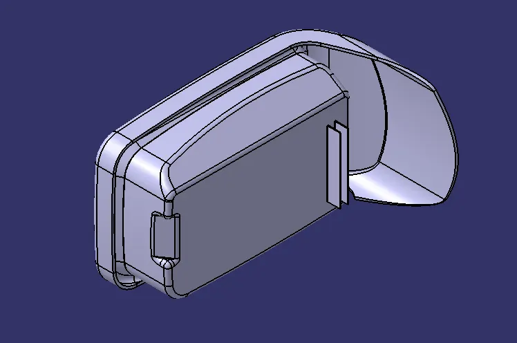
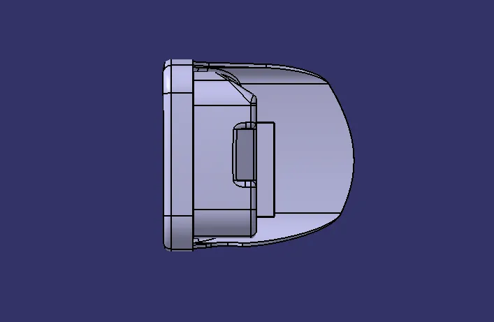
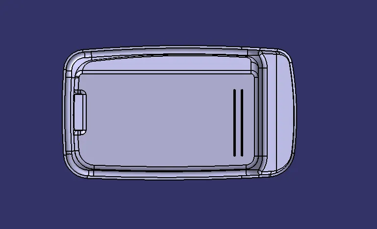
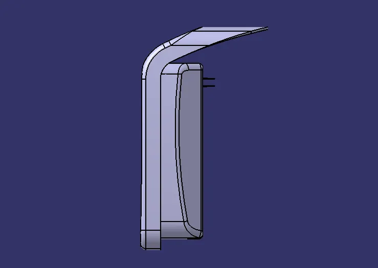
Screenshots of the completed design in various orientations (Isometric, Front, Side, and Top View)
Isometric View
Front View
Side View
Top View
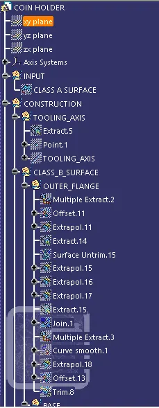
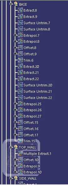
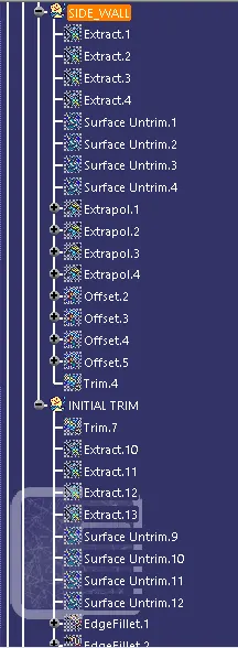
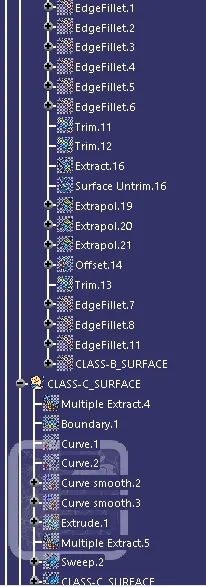
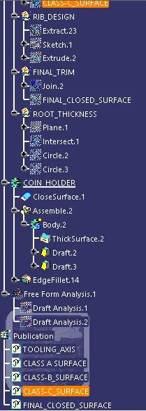
Tree Structure
Conclution
From the given input surface( class- A) the respective Class b and c surafces are created and trimmed these surfaces to form a part bodt body having 2.5 mm thick and the draft analysis also done for the final component.