3D-CAD MODELLING OF AN SHEET METAL CASING USING SIEMENS NX_CAD.12
3D-CAD MODELLING OF AN SHEET METAL CASING USING SIEMENS NX_CAD.12
OBJECTIVE
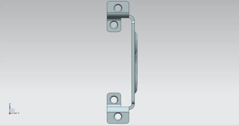
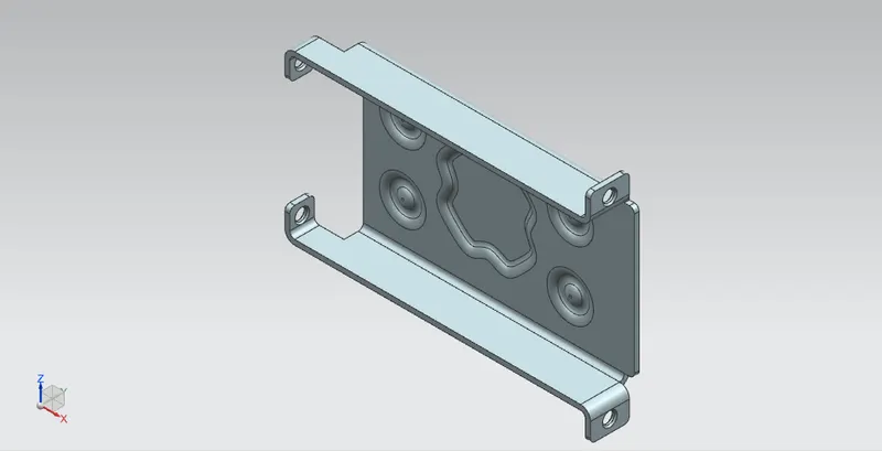
The purpose of this project is to design an aesthetic CAD model of sheet metal CASING using siemens NX_CAD sheetmatal application workbench.Also to perform the drafting for the casing part.
INTRODUCTION
The sheet metal parts can be found from the small light fixtures to the automotive body parts because of their high strength despite having low weight and its resistance to corrosion. Based on the requirements and the standards sheet metals of varying thickness are used. The sheet metal comes from various materials such as steel, aluminium, brass, titanium and more. sheet metal application provides an the envinornment for the design of the sheet metal part in machinery, automotive, enclosures, brackets and other parts normally manufactured with a barke press
Sheet metal application widely used in
- Aircraft Bodies
- Automobiles
- Utensils used for domestic purpose
- Beverage cans
SOFTWARE USED
- SIEMENS NX_CAD
DESIGN METHODOLOGY
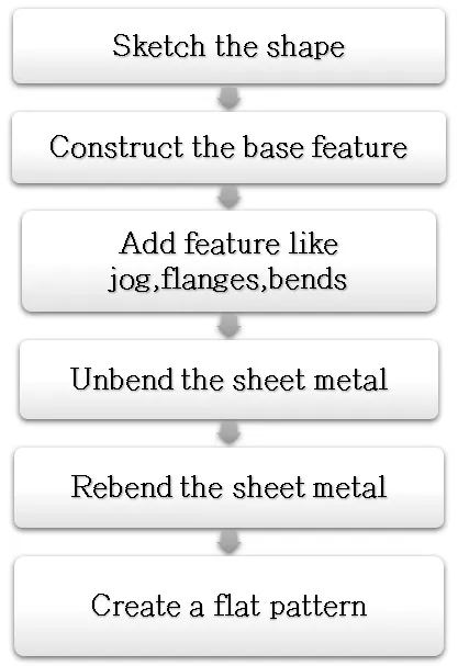
DESCRIPTION OF THE FEATURES USED
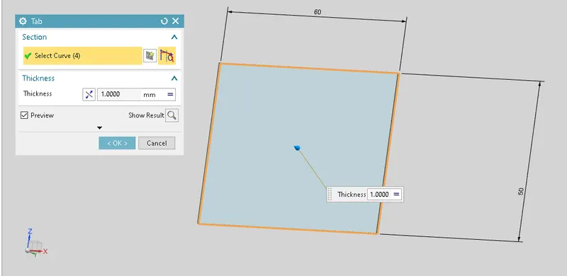
Tab- This creates a body to the sketch by adding material to it or by extruding base sketch along a vector. All further features are modelled considering tab as parent hence having a smooth flow to design. For creation of tab we first draw a sketch of profile of tab, NX allows to have both command in single go there by saving time.
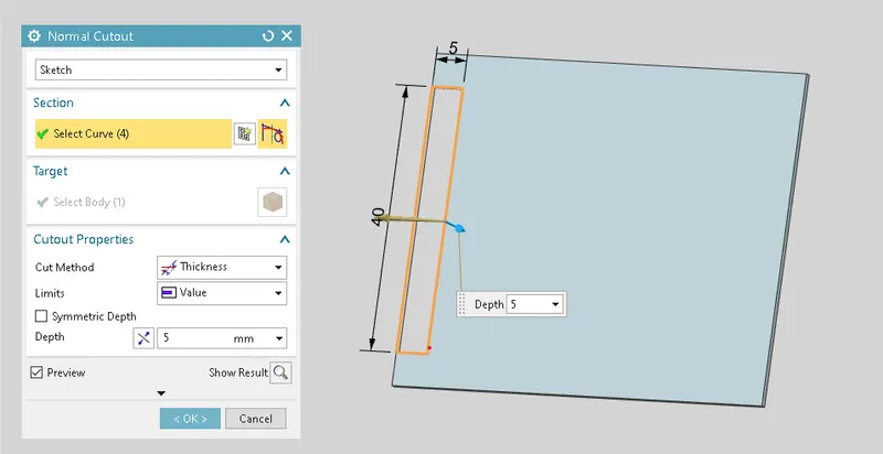
2.Normal cut-out- Normal Cutout command extract volumes from sheet metal by using sheet metal production principles. Cutting faces will be perpendicular to the sheet metal surface.
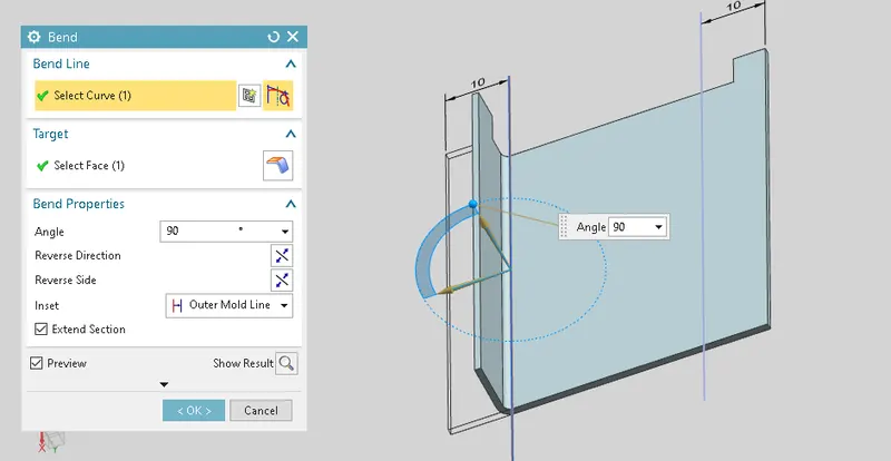
3.Bending- This feature is used to create bend in the sheet metal. To perform this operation we have to select the face and the sketch for bending.
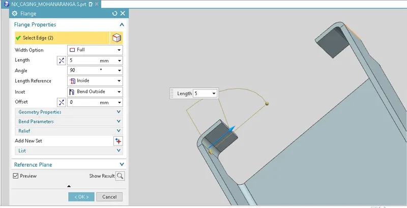
4.Flange- This feature is used to create flange by using edge of TAB or BEND at an angle and length. this feature required sigle edge to create flange
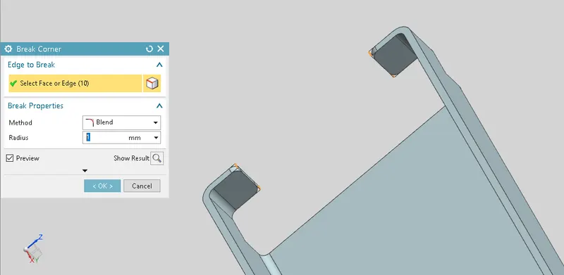
5.Break corners- This Feature is used to round the sharp edges with appropite radius
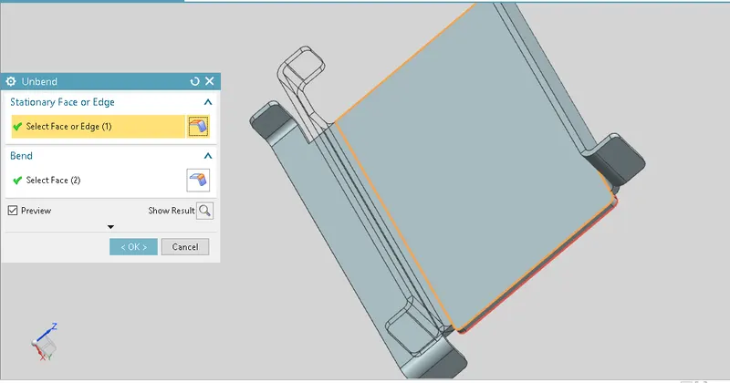
6.Unbend- This Feature is used to unbend all the adjacent bend sides and other operations
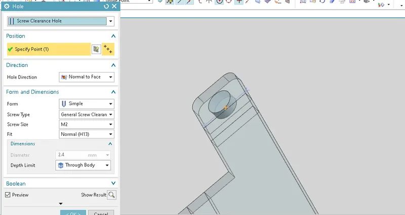
7.Hole-This command is used to create a hole in the body by removing material from the body
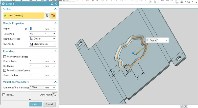
8.Dimple- This command is used to create a raised surface in upward/downward direction on a flat surface in a required shape by creating sketch
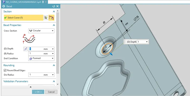
9.Bead- This command is used to give additional strength to part
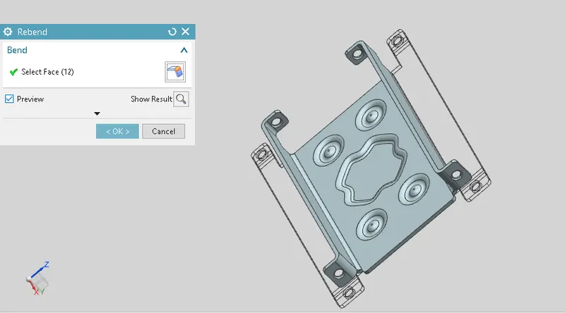
10.Re bend-This feature is used after doing required operation which is not possible to do in bend state, un bend command is used to bring the initial state which is required
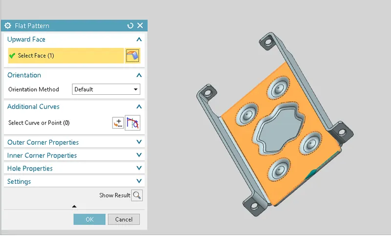
11.Flat Pattern-This feature is used after Re bending and finishing all the operation flat pattern command is used to flat the sheet metal component which is then used for drafting purpose
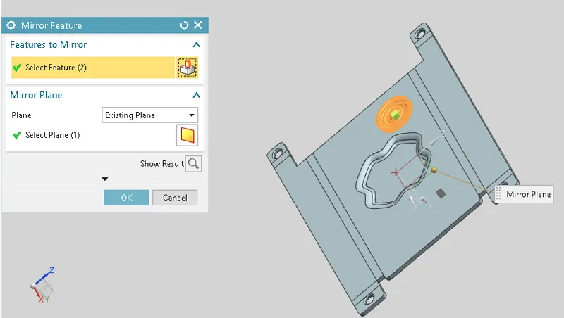
12.Mirror- This command is used to mirror a feature or body about a plane.
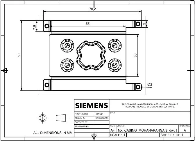
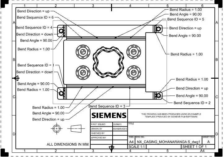
Drafting :- It is refers to creating technical drawing that communicate about dimensions, view of component geometry and other features that performed over part in 2D or 3D. The draft of drawing is prepared which include annotation, dimension, relations, etc. which helps to a person from manufacturing or production department about component . We made a drafting of flat pattern of casing on A4 Sheet in 2:1 Scale format.
FRONT VIEW
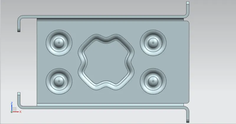
RIGHT VIEW
ISOMETRIC VIEW
CONCLUSION
Thus the modeling and drafting of the sheet metal casing is successfully created using seimens NX_cad