3D-CAD MODELLING OF AN SUNSEEKER PREDATOR YACHT WITH PHOTO-REALISTIC REANDERING USING SOLIDWORKS VISUALIZE
INTRODUCTION
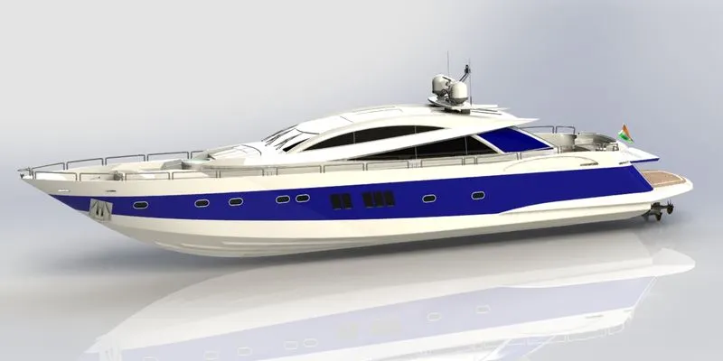
The purpose of this project is to create an aesthetic CAD model of an SUNSEEKER PREDATOR YACHT using Solidworks and photo-realistic rendering using Solidworks Visualize.
Yacht: A yacht is a Watercraft used for pleasure or sports. The term originates from the Dutch word Yacht (which means "hunt"), and originally referenced light, fast sailing vessels that the Dutch Republic navy used to pursue pirates and other transgressors around and into the shallow waters of the Low Countries. The yacht was popularized by Charles II of England as a pleasure or recreation vessel following his restoration in 1660.
OBJECTIVE
- To design every individual component of the chopper bike with suitable appearances
- To assemble all parts of the chopper in the appropriate position with proper mates
- Finally rendering the fully assembled SUNSEEKER PREDATOR YACHT to get photo-realistic view using solidworks visualize
SOFTWARE USED
- SOLIDWORKS (2021)
- SOLIDWORKS VISUALIZE (2021)
SOLIDWORKS – It is used to develop mechatronics systems from beginning to end. At the initial stage, the software is used for planning, visual ideation, modelling, feasibility assessment, prototyping, and project management. The software is then used for design and building of mechanical, electrical, and software elements
SOLIDWORKS VISULIZE- It allows you to leverage your 3D CAD data to create photo-quality content in the fastest and easiest way you can–from images to animations, interactive web content, and immersive Virtual Reality. Bring your products to life. SOLIDWORKS Visualize is the “camera” for your CAD data.
DESIGN APPROCH
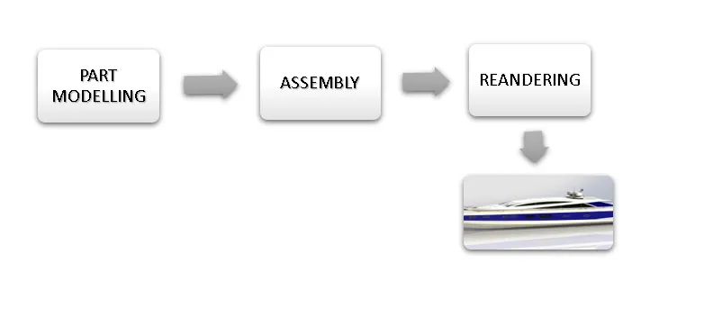
DESIGN METHODLOGY FLOW CHART
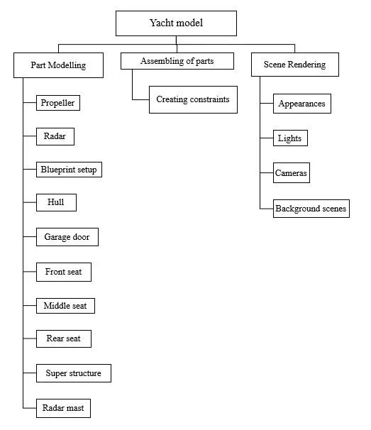
Parts of yacht
- Hull
- Superstructure
- Radar mast
- Rear seat
- Middle seat
- Front seat
- Radar
- Garage door
- Propeller
FEATURE DESCRIPTION
SKETCH:
- Sketch is a two-dimensional representation of the model with respect to the plane /view from the outside of the model. There are distinct sketch possibilities available
in solid works to create a sketch. These are referred to in solid works as Entities. The following are the parts available in Line, Arc, Spline, Circles, Rectangular solid works.
OFFSET:
- A specified distance includes one or more sketch entities, selected model edges, or model faces. For example, you may offset sketch entities such as
splines or arcs, model edge sets, loops, and so on. Finite lines, circles, and splines may be offset.
EXTRUDE BOSS/BASS:
- Extrude is a form of function available for transforming a 2D sketch into a 3D model in solid works.
LOFTED BOSS/BASS:
- The loft function creates a single feature to produce complex geometry. It provides this by interpolating surfaces between a model's different cross-sections. Sketches, faces, or edges
- maybe these cross-sections. These cross-sections are called 'Loft Profiles' in the loft interface.
FILLET:
- A rounded internal or external face on the component is created by Fillet / Round. All the edges of a face, selected sets of faces, selected edges, or edge loops can be filled.
CHAMFER:
- A cut on something's edge or corner that makes it slope slightly instead of being perfectly accurate.
SPLIT:
- The Split tool is used to project an object onto other surfaces or curved / planar faces (sketch, solid, surface, face, plane, or surface spline). You're also capable of splitting faces into
different bodies with one order.
Projected Curve:
- You can project a sketched curve onto a model face to create a 3D curve.
- You can also create a 3D curve that represents the intersection of two extruded surfaces generated by creating sketches on two intersecting planes.
- You can create multiple closed or open-contour projected curves from a single sketch. You can also use 3D sketches as input for the Projected Curve tool.
- Note: the Projected Curve tool does not support projections of intersecting curves.
DOME:
- Choose one or two planar or non-planar faces. For faces whose centroid lies outside the face, you can apply domes. This helps you to add domes to contours which are irregularly shape.
EXTRUDE CUT:
- Another great feature, extrude cut, helps remove materials from the 3D model. It is just the opposite of the boss / base extrude feature, since while extruding, it cuts a sketch profile.
You can cut in both directions and use them exclusively to create holes, channels, slots, etc.
REVOLVE:
- Create a sketch containing one or more profiles and a centreline, line, or edge that can be used as the axis around which the feature revolves. Tap on one of
the following revolving tools.
DYNAMIC MIRROR:
- The important tool in solid works is the Dynamic Mirror. When you sketch the entities, the pre-selected sketch entity mirrors them.
COMBINE:
- Combine is the type of feature available for manually merging the two bodies in solid works.
TRIM ENTITIES:
- Based on the entities you choose to trim or expand, pick the trim form. With 2D sketches and 2D sketches on 3D planes, all trim forms are available. Any of the following trim
options can be used: Power trim.
SHELL:
- For determining the thickness of thin and thick shell components, the Shell Definition Property Manager is used.
LINEAR PATTERN:
- To create a different number of instances needed to create the pattern linearly, the linear parent bodies / features are used.
CIRCULAR PATTERN:
To generate a different number of instances needed to create the pattern circularly, the circular parent bodies / functions are used.
SURFACE MODELING:
- Surface modelling allows you the opportunity to produce a visual depiction of the exterior of an object and its contours. It is, in other words, a surface. Parts such as the seat and
the classic 350 fuel tank are surface-modelled.
Loft Surface: Loft Surfaces are surfaces generated by multiple 3D Curves or existing edges creating a smooth tangency between the selected curves.
Surface trim it is used to cut away material from a surface, and provides two modes: Standard and Mutual.
Extend Surface it is used to extend the surface which is already created. There are different options available on the extended surface. We can extend the surface as same surface or we can extend the surface tangent to the surface.
Surface knit it is used to knit the two free edges/open edges of the surfaces together. Also it reduces the gap between the two edges of the surface.
Sweep Surfaces this is surfaces that are generated from a section curve positioned along a path.
Filled Surface: this Surface feature constructs a surface patch with any number of sides, within a boundary defined by existing model edges, sketches, or curves, including composite curves.
Ruled surface: it is used to obtain the extruded surface perpendicular to the plane and can be titled in certain angle
Rollback: Rollback is yet another powerful tool that allows going back to any phase of design in case if we need to edit or add some features later. We can use roll-up bar while removing errors too. This reduces the rebuild time and avoids further errors in the children features.
Combine
Combining Bodies – Add:
In a multibody part, you can combine multiple bodies to create a single body.
Combining Bodies – Subtract:
In a multibody part, you can subtract one or more bodies from another body.
- Combining Bodies – Common:
In a multibody part, you can create a body defined by the intersection of multiple bodies.
- Combine Property Manager:
In the Combine Property Manager, you specify which bodies in a multibody part to add, subtract, or overlap.
- Delete/Keep Body:
You can select bodies to keep or delete using the Delete/Keep Body feature. This is useful in working with multibody parts with multiple configurations
APPEARANCES:
- An appearance, including colours and textures, determines the visual properties of a model. Physical properties, which are determined by materials, are not affected by appearances.
A default appearance that emulates the look of the material is given to any material.
DESCRIPTION OF THE PARTS AND FEATURE USED
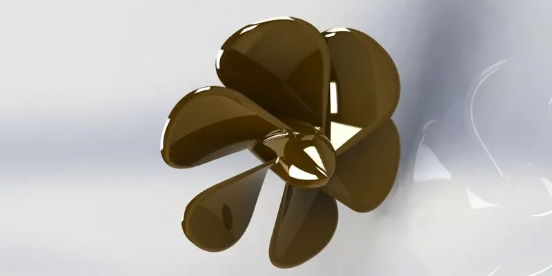
1.Propeller: -
A propeller is a device with a rotating hub and radiating blades that are set at a pitch to form a helical spiral, that, when rotated, performs an action which is similar to Archimedes' screw. It transforms rotational power into linear thrust by acting upon a working fluid, such as water or air.
Feature Tools: - Revolve Boss/Base, Cut Extrude, Circular Pattern, Fillet.
Sketch tools: - Line, spline ,3point corner rectangle, circle.
Surface Tool: - Lofted Surface
2.Radar: -
A mandatory aid to navigation, the radar is used in identifying, tracking (with integrated ARPA) and positioning of vessels (including one's own vessel) among other things in order to adhere to the COLREGs so as to safely navigate a ship from one point to another.
Feature Tool: - Boss Extrude, Fillet, Cut Extrude, Mirror. Split line
Sketch tool: - Sketch entities, Sketch Pattern.
3.HULL: -
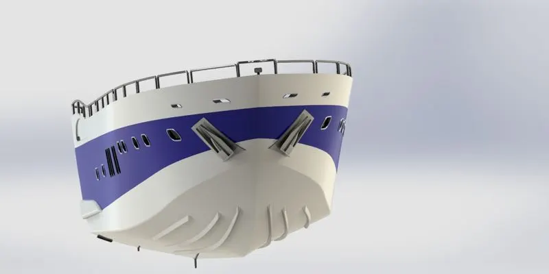
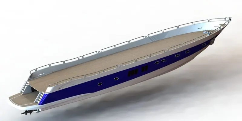
A hull is the watertight body of a ship or boat. The hull may open at the top, or it may be fully or partially covered with a deck. Atop the deck may be a deckhouse and other superstructure, such as a funnel, derrick, or mast. The line where the hull meets the water surface is called the waterline.
Hull is the main part of the Yacht. It is the giant component which extends 108ft long. It is the structure which holds all the other components of a marine vehicle. It is the part which is enclosed and water-lift is created for the movement of the vehicle on the surface of the water. The curves are sketched as close as the blueprints from 2 different views and are projected to form a 3D curve. 3D sketches are also used in this part. The Hull for this Yacht was created using the surfaces made out of the projected curves using the blueprints sketches. It consists of parts like railings, bow, deck, pulpit, anchor, garage, windows, etc
There is a wide variety of hull types that are chosen for suitability for different usages, the hull shape being dependent upon the needs of the design. Shapes range from a nearly perfect box in the case of scow barges, to a needle-sharp surface of revolution in the case of a racing multihull sailboat. The shape is chosen to strike a balance between cost, hydrostatic considerations (accommodation, load carrying and stability), hydrodynamics (speed, power requirements, and motion and behaviour in a seaway) and special considerations for the ship's role, such as the rounded bow of an ice breaker or the flat bottom of a landing craft
Feature tools: - Projected curve, Boss-Extrude, Combine, cut Extrude, Fillet, Chamfer, Swept Boss, Revolve, Dome, Linear Pattern, Helix and Spiral, Delete Face, Shell.
Sketch tools: - Sketch Entities, Convert Entities, Offset Entities, trim Entities.
Surface tools: - Surface Loft, Surface trim, Surface Extrude, Surface Knit, Surface Fill.
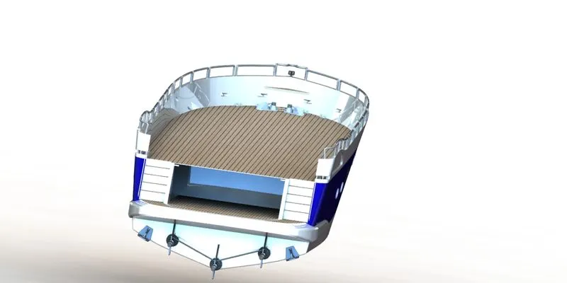
4.GARAGE DOOR
It’s a door for the Garage. A garage door is a large door on a garage that opens either manually or by an electric motor (a garage door opener).
Garage is used to store vehicle like Bike, car etc. which we want to be. Garage door helps to lock garage space.
Feature Tools: - Cut- Extrude, Shell, Fillet, Mirror.
Sketch Tools: - Sketch Entities like line, circle, etc.
5.SUPERSTRUCTURE
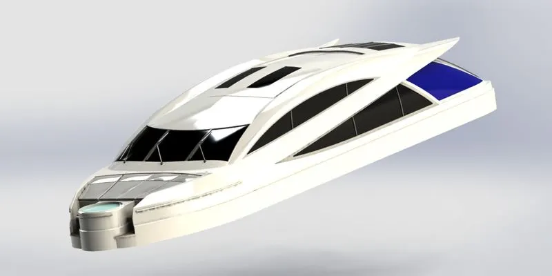
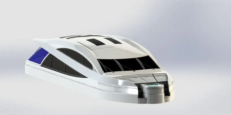
A superstructure is an extended construction of any building or platform that rises above the rest of the building or platform in a distinct manner. superstructure means to add a construction to an already existing structure. In ships this is the name given to the part of the ship that emerges from the deck. However, any mast, sails, armaments or arsenal are not included in this category.
The size of the superstructure has a great influence on the mobility of the vessels. They are designed in a manner, so that, they add value and hinder the speed and mobility in the least. The superstructure is mostly designed in fashion as well. This is because it is the most easily visible part of the ship, in fact it is the identification of the ship, and so the designers try to provide it with the identity that is unique.
It is the part that sits on the deck surface of the Yacht. In general, the superstructure of a Yacht consists of cockpits, mast, tables etc. For the modelling of this superstructure, the deck surface was used as the base so it directly inserted and fixed in position in the assembly. The curves are sketched as close as the blueprints from 2 different views and are projected to form a 3D curve. 3D sketches are also used in this part. Windows and the windscreen wipers are also included in this part. Back doors and the windows are provided with dark coloured glass.
Feature tools: -3D sketch, Projected Curve, Boss Extrude, Cut Extrude, Chamfer, fillet, Mirror, Dome.
Sketch tools: - Sketch entities, Trim Entities, Offset Entities, Convert entities.
Surface tools: - Inset Surface, Extrude Surface, Swept Surface, Offset Surface, Trim Surface, Ruled Surface, knit surface, Extend Surface, Loft surface, Surface Fill, Delete Face.
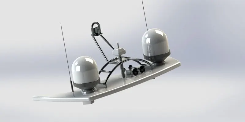
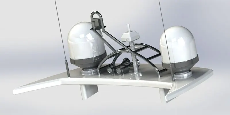
7.RADAR MAST
A mast system is composed mainly of supporting frames, a C shape base plate, radar (transmitter and receiver), and an antenna. This modelled with reference to superstructure top surface. Base plate supports all equipment components over it.
In design of Radar Mast following tools used
Feature tools: -3D sketch, Projected Curve, Boss Extrude, Shell, Chamfer, fillet, Mirror, Dome, Revolve
Sketch tools: - Sketch entities, Trim Entities, Offset Entities, Convert entities.
8.FRONT, MIDDLE, REAR SEATS
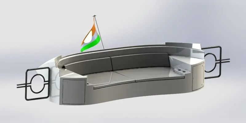
A seat is a place to sit. The term may encompass additional features, such as back, armrest, head restraint but also headquarters in a wider sense. It may also come under luxuries, materials use for the seat etc. here, this seat position on back side of the yacht.
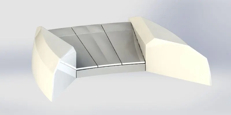
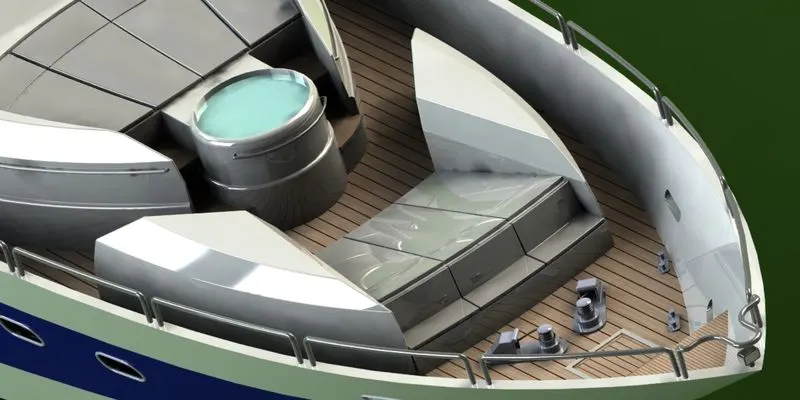
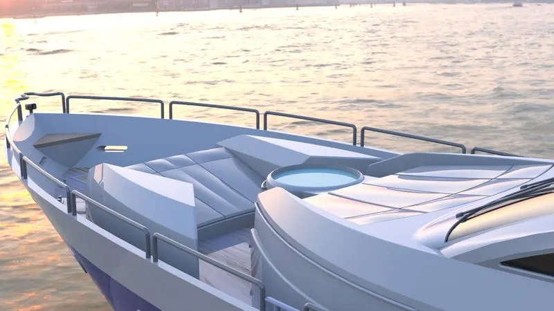
FRONT SEAT - The front seat is designed on the front to have the perfect view of the ocean and can accommodated 2 people.
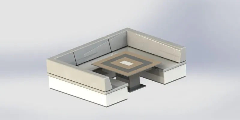
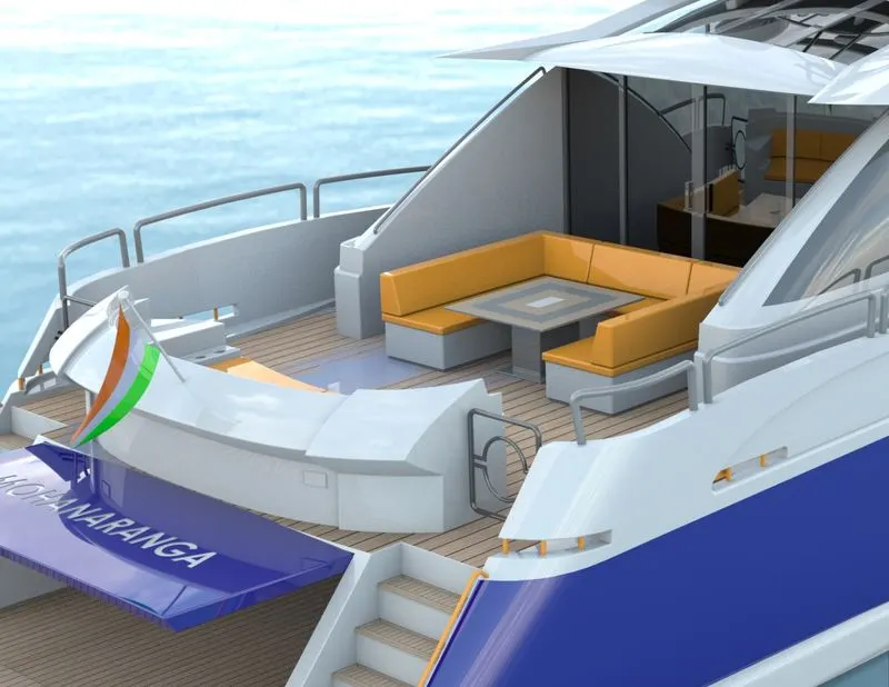
MIDDLE SEAT - The middle seats are designed to accommodate more people, It can accommodate 6 people, and a Table is provided at the centre to have a party. This is located between superstructure and the rear seat.
REAR SEAT - It is placed at the backend of the hull; it can accommodate 3 persons and gives a perfect of the backside of the ocean
Feature tools: - Revolve, Cut Extrude, fillet, Mirror, Dome, Chamfer. .
Sketch tools: -sketch Entities, Convert Entities.
Surface tools: - Inset Surface, Swept Surface, Extrude Surface, Surface Trim, Surface Fill, surface Loft and Surface Knit
FRONT SEAT
MIDDLE SEAT
REAR SEAT
ASSEMBLY
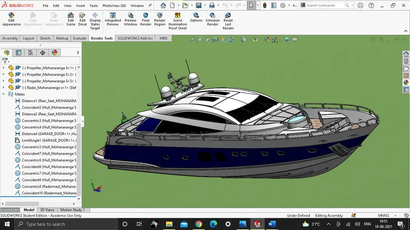
Combining multiple parts that fit together to create assemblies is called ASSEMBLY in SOLIDWORKS. We integrate the parts in an assembly using Mates, such as Concentric and Coincident. Mates define the allowable direction of movement of the components.
TYPES OF ASSEMBLY
- Top-down assembly
- Bottom-up assembly
Top-down assembly
In top-down assembly design, one or more features of a part are defined by something in an assembly, such as a layout sketch or the geometry of another part.
The design intent comes from the top, which is the assembly, and moves down to the parts. Examples of design intent include feature sizes, component placement in an assembly and proximity to other parts.
For example, you create a locating pin on a plastic part using the Extrude command. You choose the Up to Surface option and select the bottom of a circuit board, which is a different part. This selection makes the locating pin long enough to touch the board, even if the board moves in a future design change. The length of the pin is defined in the assembly, not by a static dimension in the part.
Bottom-up assembly
Bottom-up design is the traditional method. You first design and model parts, then insert them into an assembly and use mates to position the parts. To change the parts, you must edit them individually. These changes are then seen in the assembly.
Bottom-up design is the preferred technique for previously constructed, off-the-shelf parts, or standard components like hardware, pulleys, motors, etc. These parts do not change their shape and size based on your design unless you choose a different component.
Feature used for assembly
- Insert component
- Mates
- Mirror
Steps involved in the assembly
- Open all the parts of the chopper at once in solidworks
- Insert one by one in the assembly part and start giving appropriate relation
- After inserting the parts start giving the mates to get assembled in the appropriate manner
- Finally make sure all parts are fully defined with proper mates
Rendering
Rendering or image synthesis is the process of generating a photorealistic or non-photorealistic image from a 2D or 3D model by means of a computer program. The term "rendering" is also used to describe the process of calculating effects in a video editing program to produce the final video output.
Rendering of American Chopper model is done by using PhotoView-360 and Solidworks Visualization.
PhotoView-360
PhotoView-360 is a visualization and rendering solution included with SOLIDWORKS Professional and SOLIDWORKS Premium. It Provides a highly interactive environment for viewing designs as well as for creating photo-realistic renderings that can be used to showcase our designs.
The PhotoView 360 software
PhotoView 360 is a software solution from Solidworks, fully integrated into the Solidworks software to create photorealistic images directly from Solidworks models. Renderings may be created from Solidworks parts and assemblies, but not drawings. PhotoView 360 can produce photorealistic images to add visual impact to presentations and documents.
Some of the key features of PhotoView 360 are:
- Photorealistic images directly from Solidworks models
- PhotoView 360 interacts with the 3D geometry created with the Solidworks software. All changes to Solidworks models are accurately represented in the PhotoView 360 images.
- Fully integrated into Solidworks.
- PhotoView 360 software is supplied as a Solidworks add-in.
PHOTOVIEW 360 RENDERED IMAGE
SOLIDWORKS Visualize
Quickly and easily create professional, photo-quality images, animations, and other interactive 3D content to get your products to market faster.
SOLIDWORKS Visualize allows us to leverage our 3D CAD data to create photo-quality content in the fastest and easiest way we can–from images to animations, interactive web content, and immersive Virtual Reality. It brings our products to life. SOLIDWORKS Visualize is the “camera” for our CAD data.
Some renderers are fast but output low-quality images. Some produce great quality but take six months to learn. Others are easy to use, but take four hours to render an image. SOLIDWORKS Visualize provides the right combination of quality, speed, and ease of use, and is the best renderer.
SOLIDWORKS VISUALIZE PROFESSIONAL
With SOLIDWORKS Visualize Professional we can tell a deeper 3D story about our product using our CAD data. It enables us to easily generate photo-quality stills and interactive animations to effectively communicate the most complex design details.
The features of SOLIDWORKS Visualize Professional are listed below,
o Demonstrate products more effectively with full animation of parts, models, appearances, cameras, and environments
o Import our SOLIDWORKS CAD Motion Studies for truly photographic animations
o Quickly show off the final design with one-click 360-degree spins
o Create interactive web content such as Interior Panoramas and Exterior VRs
o Present and compare varying design solutions side-by-side with multiple viewports and included Configurator tool
o Unleash our creative side with customizable Camera Filters
SOLIDWORKS Visualize Professional also includes key features to help increase productivity. The integrated Render Queue allows us to stack up jobs on our machine or a dedicated render farm to automatically complete one after the other, providing remarkable time savings.
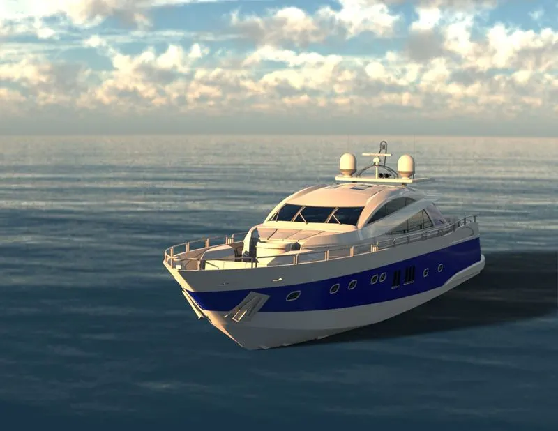
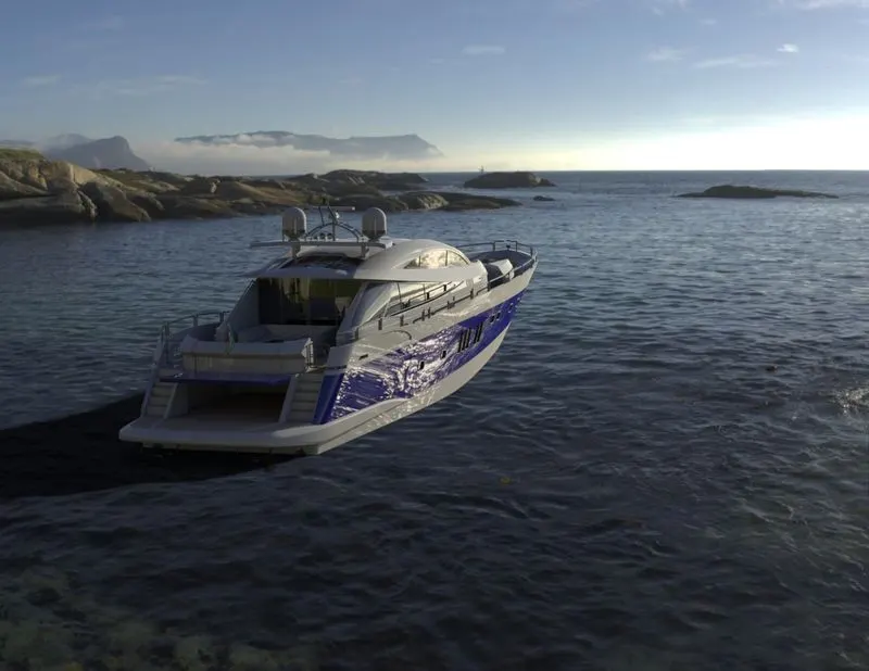
RENDERED IMAGE OF THE YACHT
FRONT VIEW
FRONT PART OF THE YACHT
BACK VIEW
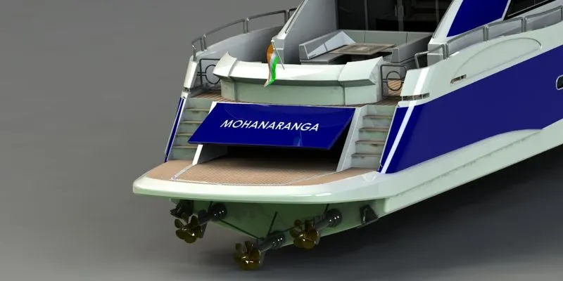
REAR PART OF THE YACHT
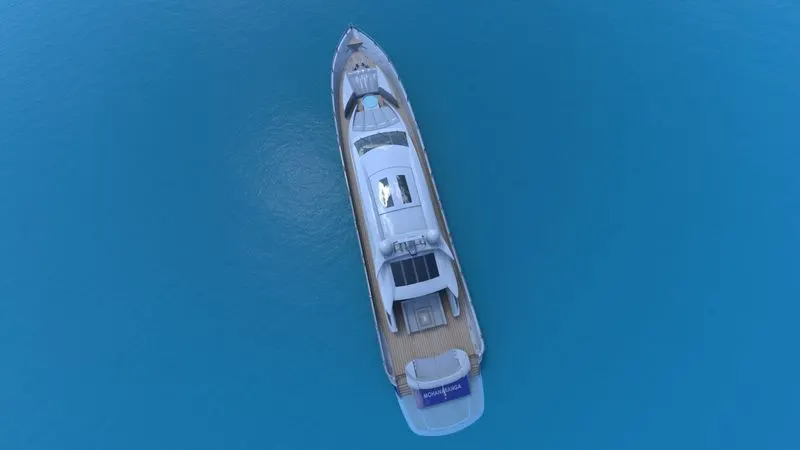
TOP VIEW
CONCLUSION
Thus, the 3d-cad modelling of an SUNSEEKER PREDATOR YACHT with SOLIDWORKS 2021 and photo-realistic rendering using PHOTOVIEW 360 and SOLIDWORKS VISUALIZE has been successfully completed