PASSANGER CAR HOOD OUTER AND INNER PANEL DESIGN USING SIEMENS NX_CAD 12.1
DESIGN OF BIW COMPONENT- HOOD OUTER AND INNER PANEL
OBJECTIVE:
The main purpose of this project is to design a hood of a car with the given master section and by following necessary safety precaution.
INTRODUCTION:
WHAT IS HOOD OR BONNET?
A car hood, also referred to as a bonnet in some other countries, is the hinged cover that rests over the engine of a front-engine vehicle. Its purpose is to provide access to the engine for repair and maintenance. A concealed latch is typically used to hold down the hood. On vehicles with an aftermarket hood and on race cars, hood pins may be used to hold down the car hood. Hoods sometimes also contain a hood scoop, wiper jets, power bulge, and/or hood ornament. Car hoods are typically constructed from steel and sometimes from aluminium. Aftermarket car hoods may be constructed from various other materials, including carbon fibre, fiberglass, or dry carbon. The hood design may vary from one make and model to another, including SUV, crossover, truck, minivan and passenger-car models.
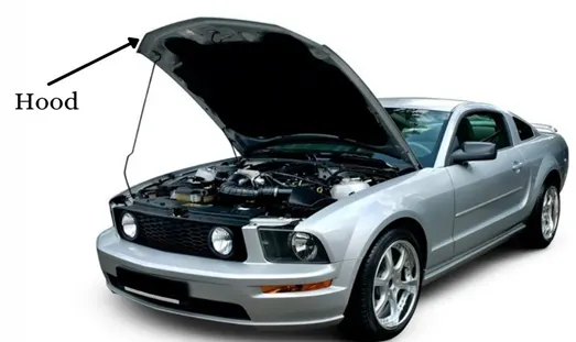
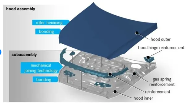
Concerns regarding the severity of a potential pedestrian head injury during a collision with a motor vehicle have led to advanced hood designs on many models. Such designs may include a multi-cone inner hood panel design. An active structure that is capable of pushing the surface of the hood away from the vehicle's hard motor components in the event of a pedestrian crash is also in use. Pyrotechnic or spring force designs are often used in active-hood design.
WHY DO WE NEED A HOOD?
The main function of the car hood is to protect the components underneath it for example, the engine. Without this protection, small stones kicked up by other cars could puncture a fluid container or damage the engine. In addition, most engines are not supposed to be exposed to excess water. It makes your car more beautiful
In most modern vehicles, internal combustion engines "breathe" under-hood air or air ducted from under the front bumper through plastic and rubber tubing. The high operating temperatures in the engine compartment result in intake air that is 28°C (82°F) or warmer than the ambient temperature, and consequently less dense. A hood scoop can provide the engine with cooler, denser outside air, increasing power.
The following are some of the important purposes of the Hood or Bonnet
- Safety of the passenger.
- Covers all engine, radiator, and other necessary components.
- Reduce air effect due to its aerodynamic shape design.
- Reduce engine noise which helps for a quieter drive.
- Provide access to engine maintenance.
- Absorbs most of the impact forces when a frontal crash occurs.
Hood scoop:
A bonnet scoop or hood scoop, sometimes called bonnet air dam, is an upraised component on the hood of a motor vehicle that either allows a flow of air to directly enter the engine compartment, or appears to do so. It has only one opening and is closed on all other sides. Its main function is to allow a direct flow of air to the engine, hence the need for it to be upraised so as to effectively channel air to the engine compartment. It may be closed, and thus purely decorative, or serve to enhance performance in several possible ways.
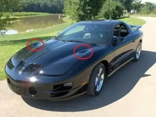
Cool air
In most modern vehicles, internal combustion engines "breathe" under-hood air or air ducted from under the front bumper through plastic and rubber tubing. The high operating temperatures in the engine compartment result in intake air that is 28°C (82°F) or warmer than the ambient temperature, and consequently less dense. A hood scoop can provide the engine with cooler, denser outside air, increasing power.
Ram air
At higher road speeds, a properly designed hood scoop known as ram-air intake can increase the speed and pressure with which air enters the engine's intake, creating a resonance supercharging effect. Such effects are typically only felt at very high speeds, making ram air primarily useful for racing, not street performance.
Pontiac used the trade name Ram Air to describe its engines equipped with functional scoops. Despite the name, most of these systems only provided cool air, with little or no supercharging effect.
Inter-cooler scoops
Some engines with turbochargers or superchargers are also equipped with top mounted intercoolers to reduce the temperature and increase the density of the high-pressure air produced by the compressor. Channelling outside air to the intercooler (which is a heat exchanger similar to a radiator) increases its effectiveness, providing a significant improvement in power.
PEDESTRAIN SAFETY
Pedestrians are the most vulnerable road users who are at the high risk of vehicle collisions in traffic, almost 1.2 million pedestrians are killed annually in road traffic accidents worldwide. The major injuries occur in lower, upper leg and head of the pedestrian, where the fatalities of the pedestrians in the accident is mainly due to head injury resulting from the hard impact of the head against the stiff hood or to the ground. In recent years, engineers are working on the vehicle front end design which includes bumper and hood to reduce the injuries to the pedestrians in the event of pedestrian vehicle collision.

Euro NCAP is a voluntary vehicle safety rating system created by the Swedish Road Administration, the International Consumer Research & Testing, backed by members, and motoring & consumer organisations in several EU countries.They provide consumers with information regarding the safety of passenger vehicles. In 1998, operations moved from London to Brussels.
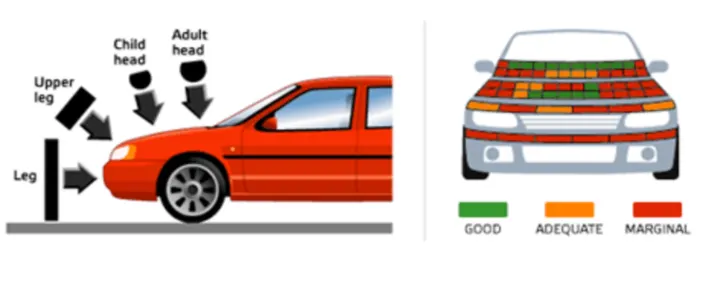
Many pedestrian crashes involve a forward moving car (as opposed to buses and other vehicles with a vertical hood/bonnet). In such a crash, a standing or walking pedestrian is struck and accelerated to the speed of the car and then continues forward as the car brakes to a halt. The pedestrian is impacted twice, first by the car and then by the ground, but most of the fatal injuries occur due to interaction with the car. Vehicle designers usually focus on understanding the car-pedestrian interaction, which is characterized by the following sequence of events: the vehicle bumper first contacts the lower limbs of the pedestrian, the leading edge of the hood hits the upper thigh or pelvis, and the head and upper torso are struck by the top surface of the hood and/or windshield.
Pedestrian Head Impact Zone
1.Wrap Around Distance
When a car crashes on the pedestrian, the whole human body wraps around the front shape of the car and the head impacts on the bonnet or the windscreen. The distance on which the head impacts on the car from the ground is called as the Wrap Around Distance (WAD).
To be specific the Wrap Around Distance is a measurement of distance from the ground to the head impact zone over the outer surface of the car. The wrap around distance is measured longitudinally in the centre of the vehicle from the ground.
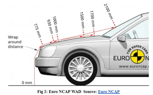
The severity of the injury caused by the frontal crash depends on the type and shape of the vehicle, speed of the vehicle and the movement of the pedestrian relative to the vehicle. In addition to these parameters, the wrap around distance plays a major role in the safety measurement of a pedestrian.
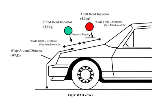
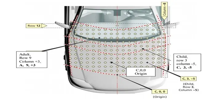
During the crash analysis, based on the Wrap Around Distance (WAD), two test areas will be created namely Child head impact zone and the Adult head impact zone. The child head impact zone is between 1000 to 1700 mm WAD and the adult head impact zone ranges between 1700 to 2100 mm WAD.
2.Bonnet Side Reference Line
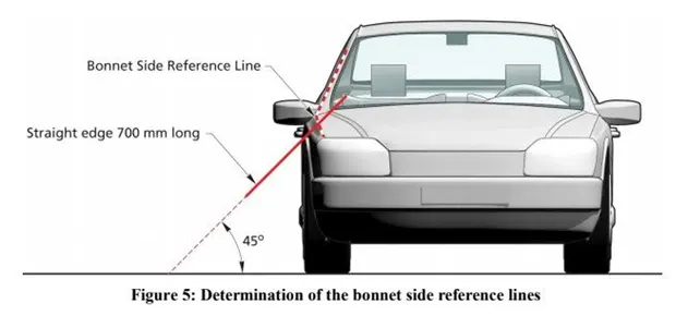
The Bonnet Side Reference Line is defined as the geometric trace of the highest points of contact between a straight edge 700mm long and the side of a bonnet, as defined in Section 3.3.1 and A-Pillar, when the straight edge, held parallel to the lateral vertical plane of the car and inclined inwards by 45 deg is traversed down the side of the bonnet top and A-Pillar, while remaining in contact with the surface of the body shell, any contact with door mirrors is ignored. Where multiple or continuous contacts occur the most outboard contact shall form the bonnet side reference line.
3.Bonnet Leading Edge Reference Line
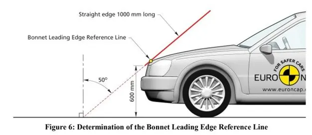
The Bonnet Leading Edge Reference Line is defined as the geometric trace of the points of contact between a straight edge 1000mm long and the front surface of the bonnet, when the straight edge, held parallel to the vertical longitudinal plane of the car and inclined rearwards by 50 degree and with the lower end 600mm above the ground, is traversed across and in contact with the bonnet leading edge. For vehicles having the bonnet top surface inclined at essentially 50 degree, so that the straight edge makes a continuous contact or multiple contacts rather than a point contact, determine the reference line with the straight edge inclined rearwards at an angle of 40 deg. For vehicles of such shape that the bottom end of the straight edge makes first contact then that contact is taken to be the bonnet leading edge reference line, at that lateral position. For vehicles of such shape that the top end of the straight edge makes first contact then the geometric trace of 1000mm wrap around distance will be used as the Bonnet Leading Edge reference line at that lateral position. The top edge of the bumper shall also be regarded as the bonnet leading edge, if it is contacted by the straight edge during this procedure.
- Child Impact Zone: 1000-1500 mm
- Adult Impact Zone: 1500-2100 mm
Impact Point Location
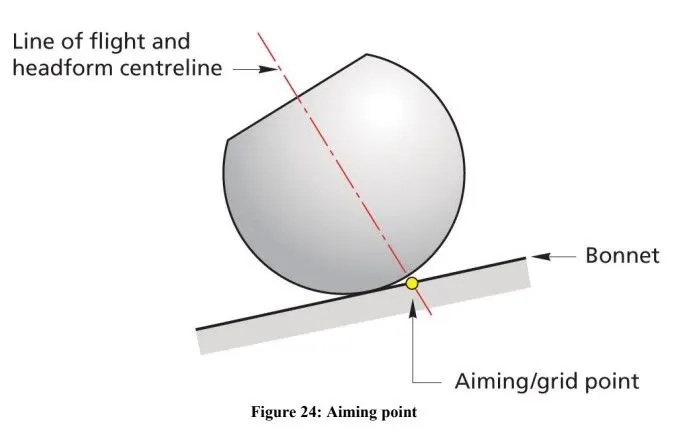
Manufacturer has to provide the Euro NCAP Secretariat with colour data at all grid points. Data must be supplied by the manufacturer before, the testing of the vehicle begins. The predicted level of protection offered by the vehicle is verified by EURO NCAP. Alternatively test points will be selected on the basis of worst-case performance basis.
Pedestrian Head Injury Criteria & Rating
The head injury criterion (HIC) is a measure of the likelihood of head injury arising from an impact. The HIC can be used to assess safety related to vehicles, personal protective gear, and sport equipment. Normally the variable is derived from the measurements of an accelerometer mounted at the centre of mass of a crash test dummy’s head, when the dummy is exposed to crash forces.
where t1 and t2 are the initial and final times (in seconds) chosen to maximize HIC, and acceleration a is measured in gs. The time duration, t2 – t1, is limited to a maximum value of 36 ms, usually 15 ms. This means that the HIC includes the effects of head acceleration and the duration of the acceleration. Large accelerations may be tolerated for very short times. At a HIC of 1000, there is an 18% probability of a severe head injury, a 55% probability of a serious injury and a 90% probability of a moderate head injury to the average adult.
HOOD STAY
A hood stay is an apparatus for an engine room of a car, which can safely keep an engine hood in an open state even if an external force is abruptly generated due to vibration, wind and can facilitate an opening/closing operation of the engine hood.
TYPES OF HOOD SUPPORT
- Gas stay
- Support Rod
1.Gas Stay
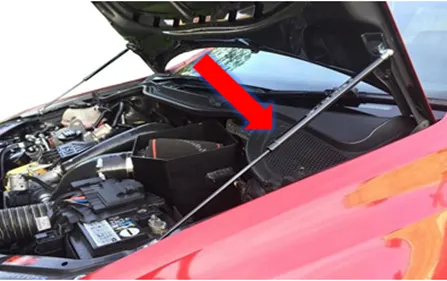
These are used to lift the car hood. Its purpose to just give the lifting force to the hood, then it automatically opens the car hood by means of gas pressure. This is used where the car bonnet size is heavy to lift. Spring stays are designed to be used on upward lifting doors, once you have opened the door slightly the spring will push the door to the fully open position. Struts contain nitrogen gas under pressure and some oil to damp movement and to lubricate the seals.
2.Support rod
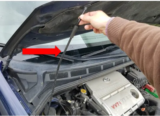
This is widely used in many cars as the rate is cheap. In this type we have to lift the hood by ourselves and place the support rod in the space provided either in the hood or engine component. This is mostly used for where the car bonnet weight is small. Support Rod can be mounted with grommet side on the engine compartment of body and rod locking hole on hood or vice versa. Grommet and the clip of the rod are standard parts. Support rod is used to increase the support force, automatic buffering, stable and reliable, strong load-bearing capacity, safe use, not easy to fall, avoid hot hands, support the engine more easily, and balance the force without shaking.
Components of the Hood/Bonnet
Outer panel:
The outer panel is actually called the skin of the vehicle which is designed by the styling team to get a good look for a vehicle by covering the inner panel and engine parts of the car. This part should not be welded to the inner panel but using the sealant and mastic points makes contact between the inner and outer panel which acts as a bond between both and makes the hood stiff.

Inner panel:
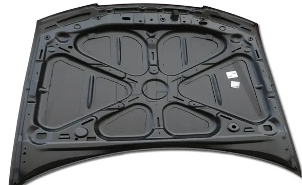
The main part of the hood which gives support to the outer panel of the car and with its embossing shapes dissipates the force in different directions when the vehicle takes crashes to not to injure the men in the car.
Latch/striker
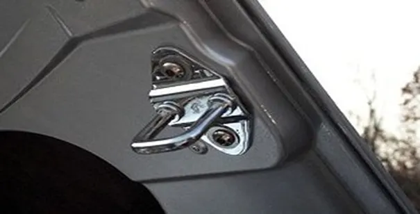
It is a part that helps in locking the hood with the striker which is mounted on the engine block when it is not in use. It plays a major role in opening and closing hood for maintenance of car engine and gives a tight locking position not to create undisturbed noises when the vehicle is running.
Hinges:
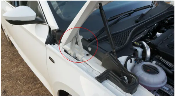
The hinge consists of two parts- hinge at the inner panel and hinge at the engine compartment. This coupling allows the hood to open and close, as well as makes contact between the engine block to the hood. It also controls the lifting of the bonnet mitigates the consequences of a collision between a pedestrian and a vehicle.
DESIGN OF HOOD
For designing the hood or bonnet, master section and class A surface has been given for the reference.
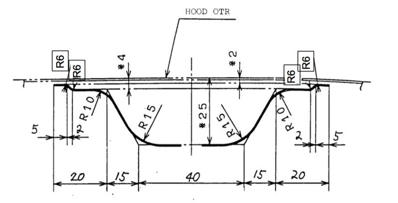
MASTER SECTION: Master sections are the guides for design requirements which decide the component packaging after technical (Styling, Concept or Class-A) surfaces.
CLASS A SURFACE: In automotive design, a class A surface is any of a set of freeform surfaces of high efficiency and quality. Although, strictly, it is nothing more than saying the surfaces have curvature and tangency alignment – to ideal aesthetical reflection quality, many people interpret class A surfaces to have G2 (or even G3) curvature continuity to one another (see free form surface modelling). Class A surfacing is done using computer-aided industrial design applications. Class A surface modellers are also called "digital sculptors" in the industry. Industrial designers develop their design styling through the A-Surface, the physical surface the end user can feel, touch, see etc.
Design Methodology
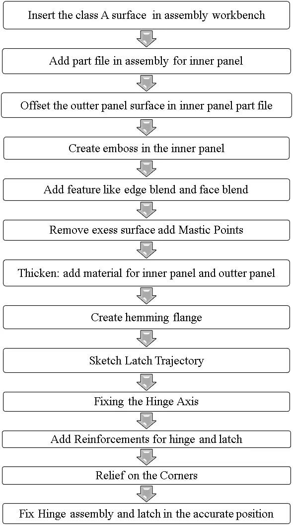
DESIGN CONSIDERATIONS FOR DESIGNING THE HOOD
1.Latch Trajectory
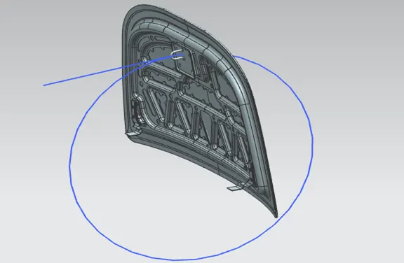
The latch trajectory shows the path of the striker when the hood is opened and closed on a vehicle. The radius of the circular trajectory is determined by the set standard based on the average height of a person. The radius is measured from the hinge axis up-to the latch.
2.Fixing the Hinge Axis
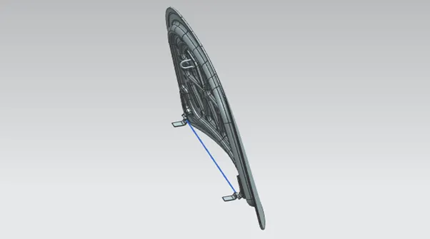
The hinge axis is positioned in such a way that the axis lies in the same line so that it is parallel to the “x” axis plane. This is done in order to position the latch and sticker trajectory motions exactly perpendicular to the hinge axis.
3.Mastic Points
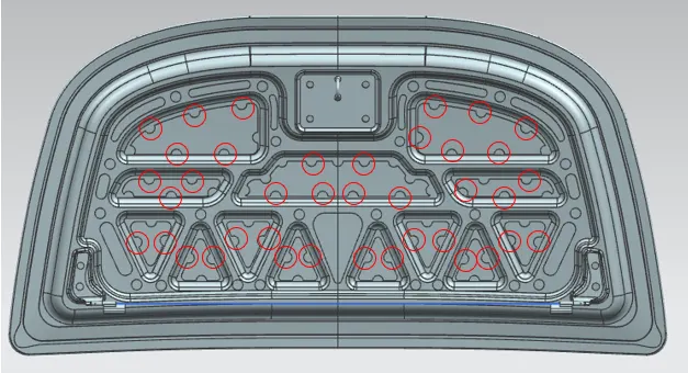
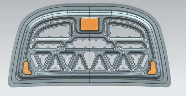
The mastic points are areas where the mastic is placed to attach the outer panel to the inner panel. We cannot use spot welding as it would give a less aesthetically pleasing result. Hence mastics are used to join the panels together as it does not melt the metal itself.
4.Emboss Definitions
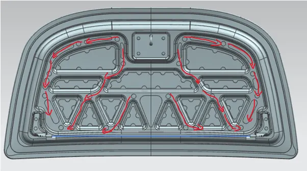
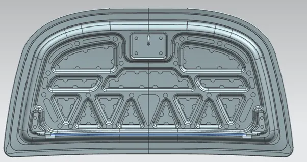
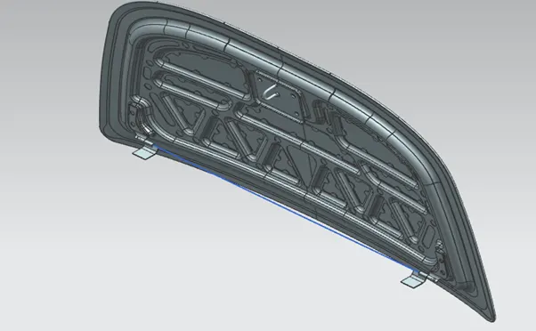
The inner panel consists of various embosses which help dissipate the force during impact. The width and depth of the emboss is determined by simulations and analysis to check for failure. These emboss definitions are created at an angle so that they point away from the centre of the hood when viewed from the front of the vehicle.
5.Reinforcements
The area near hinge and latch has more chances of failure in the hood panel. Hence to avoid any failure, the hinge and latch areas are reinforced with extra material whose thickness is usually determined by the type of vehicle.
6.Dissipating Shock Waves
To dissipate the shock waves on to the sides of the hood. This is a major reason for designing the hood in the shape of “Y” or “V” to dissipate the forces on the sides. This is one of the primary reasons for designing it in such a way that the force is not carried on to the passengers inside so that the passengers are saved from possible damage. In this design it is found that the embosses are designed such that it forms the shape of “Y”.
7.Relief on the Corners
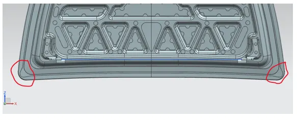
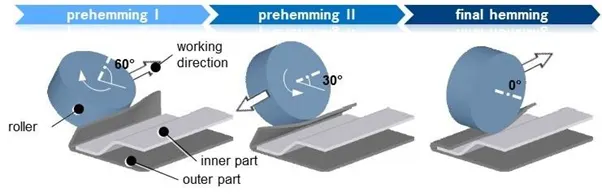
A relief on the corners is provided for the hemming process in order to avoid spring back issues. When the rollers are moving on the panels the force that is used to bend the sheet metal has to be maintained within the limit to avoid spring back issue. Due to which a relief is given on the corners to avoid the red zones on the hood.
8.Hemming In Sheet Metals
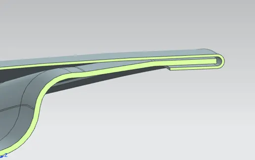
Sheet metal is metal, in sheets. It’s thinner than plate metal (.25 in and thicker) but thicker than foil (.006 in and thinner). It’s most commonly available in steel and aluminium, in various gauges (thicknesses). It’s available with various coatings for corrosion resistance or surface finish. Sheet metal is made by taking a large cast ingot and rolling it into a long ribbon of the desired thickness. This long, flat piece of metal is then rolled into a coil and sent directly or cut into sheets before being sent to a machine shop.
Manufacturing Processes Involved in Hood Design
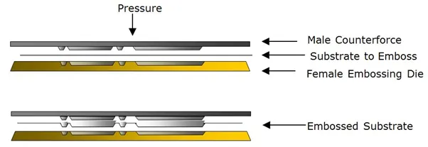
1.Embossing (Manufacturing)
Sheet metal embossing is a stamping process for producing raised or sunken designs or relief in sheet metal. This process can be made by means of matched male and female roller dies, or by-passing sheet or a strip of metal between rolls of the desired pattern. It is often combined with Foil Stamping to create a shiny, 3D effect
2.Deep Drawing
Deep drawing is a sheet metal forming process in which a sheet metal blank is radially drawn into a forming die by the mechanical action of a punch. It is thus a shape transformation process with material retention. The process is considered "deep" drawing when the depth of the drawn part exceeds its diameter. This is achieved by redrawing the part through a series of dies. The flange region (sheet metal in the die shoulder area) experiences a radial drawing stress and a tangential compressive stress due to the material retention property. These compressive stresses (hoop stresses) result in flange wrinkles (wrinkles of the first order). Wrinkles can be prevented by using a blank holder, the function of which is to facilitate controlled
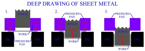 material flow into the die radius.
- Hemming Process
Sheet metal is metal, in sheets. It’s thinner than plate metal (.25 in and thicker) but thicker than foil (.006 in and thinner). It’s most commonly available in steel and aluminium, in various gauges (thicknesses). It’s available with various coatings for corrosion resistance or surface finish. Sheet metal is made by taking a large cast ingot and rolling it into a long ribbon of the desired thickness. This long, flat piece of metal is then rolled into a coil and sent directly or cut into sheets before being sent to a machine shop.
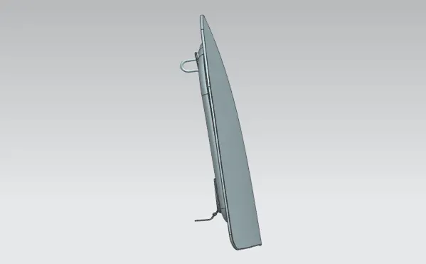
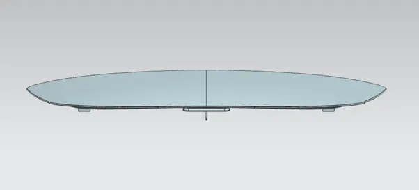
Different Views of The Designed Hood
Front View
Right View
Top View
Isometric View
CONCLUSION
Thus, with the give master section and class A surface model the hood have been designed as per the euro NCAP guidelines Using siemens NX_CAD. The main aim was to improve the pedestrian safety rating by reducing the risk of injuries