Week 8 - Challenge 4 - Coin Holder Design
AIM
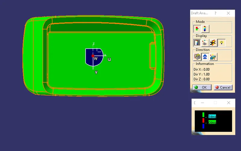
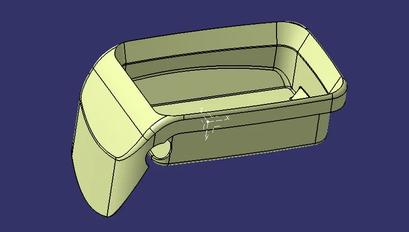
To Create the Coin Holder Plastic component through the given Class-A surface. To begin with, the tooling axis for the given Class-A Surface should be created meeting the requirements of the draft angle and at the end perform the Draft analysis on the model.
INTRODUCTION
Draft angle and Why it is needed?
Draft is an angular taper given at the design stage to every Plastic Component that has to be manufactured. It is given in the direction of the Mold Movement. The Draft allows the parts to release easily from the mold without creating any damage between the surface of component and the core and cavity plates.
When a Plastic component cools down inside the mold, the natural tendency of it is to shrink and attach to the core or cavity half. The movement of mold opening causes friction on the walls of the component as well as the core/cavity blocks. This reduces the life of the mold as well as the component itself. The component may also have rough surface finish as well as weak structure due to this. This problem can be solved by giving draft to the component.
The general draft angles used in the industries for different purposes.
- 0.5 degrees on all vertical faces is strongly advised.
- 1 to 2 degrees works very well in most situations.
- 3 degrees is minimum for a shutoff (metal sliding on metal).
- 3 degrees is required for light texture.
- 5 or more degrees is required for heavy texture.
Tooling axis
The tooling axis is basically the direction that the mold pills apart. The mold is built in two separate pieces basically. You have a cavity side and you have the core side. The core pulls apart from the cavity and that is the dyeline or the tooling direction.
The draft angle, which also plays a major role in plastic component design, is decided with reference to the main tooling axis of the component
What is Draft Analysis?
No parts can be ejected from the tool if it is having a straight 90 degree profile from its base surface. A small draft angle is provided to each and every area of the component in order to get an easy removal of the component from the tool. Draft analysis technique is used to analyze whether our part model created in cad is manufacturable based on the draft condition applied. Here the part should get easily removed from the panel dies (in case of Sheet metal part) or Mold (in case of plastic). Here we are providing a direction in which components should eject inorder to get an easy removal of components from the tool. In other words it also lets us know whether the model is having a draft angle and how much is the draft angle from the tool direction.
On what type of components we perform Draft Analysis?
Draft analysis is performed on the components where the ejection of materials happens after the material is made inside the tools. In case of Automotive Sheet Metal manufacturing, the blank sheet after turning into automotive panels like Hood, Fender, Roof, Side Doors, Back Doors etc. need to be removed from Panel Dies. If a considerable amount of draft angle is not provided, the removal components from the tool will be difficult. Same in the case of mold(plastic component) after getting filled inside the core and cavity, it needs to get ejected easily with the help of ejectors.
What factors should be considered while doing the draft analysis for Plastic/Automotive Sheet Metal parts?
The major consideration of Draft Analysis is whether sufficient Draft Angle is provided on the component. Components while designing should be provided with a considerable amount of draft angle depending on the manufacturing consideration. For Plastic components we provide a draft angle of 3degree(Draft angle of 0.5 is given ideally to the features inside the plastic part). But for Automotive Sheet Metal Parts, it will be from 7 degrees or more.
1.) Createing Tooling Axis
Component :- Coin Holder
Software used:- CATIA v5
Procedure
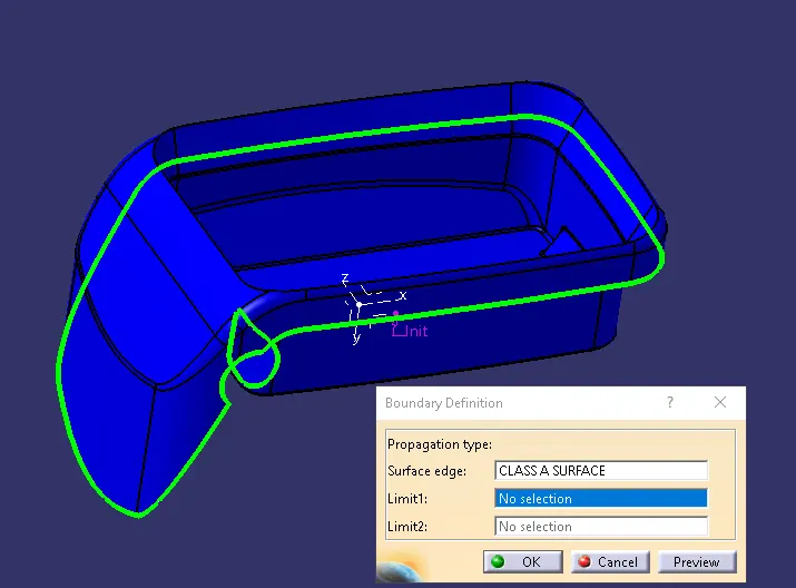
Step-1: Continuity check on class-A surface of Coin Holder
Initially for any class-A surface , first step is to check wheather the surface has continuity without any breaks and disjoints in it.
STEP-2
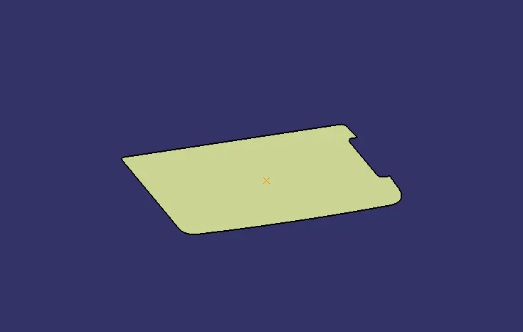
Extract the base surface of the given Class- A Surface and create the center point of the Extracted surface.
STEP-3
Then the tooling axis created using line commend which is normal to the extracted surface.
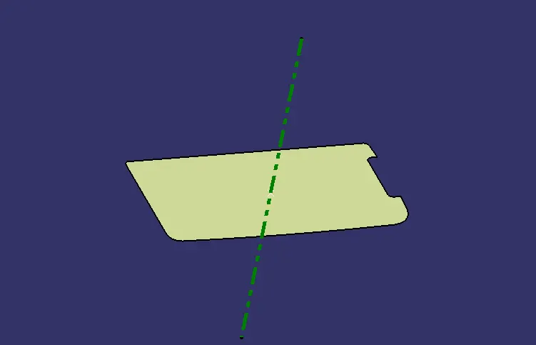
2.) Performing Draft analysis on Coin Holder
Component :- Coin Holder
Software used:- CATIA v5
1.) Procedure for draft analysis on Class-A surface
Step-1- Choose the Feature Draft Analysis command from the Analysis toolbar marked in red box.
Insert-> Analysis-> Draft analysis
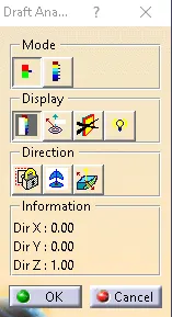
Step-2- Enable the compass feature in the Draft Analysis Toolbar as shown below.
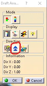
Step-3- Place the compass on the required position and along the desired tooling direction on the part
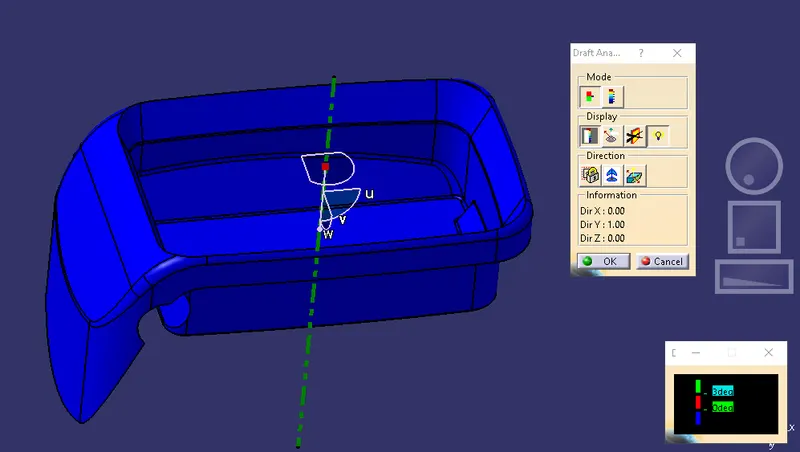
Step-4- Select the part on which draft analysis has to be performed. The part turns to the combination of colors present in the scale
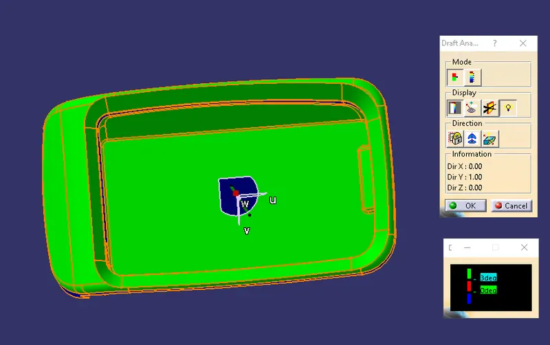
Step-5- Analyse the part with respect to the results obtained based on the scale, to identify the parts with draft feature. Quick analysis mode was chosen for the analysis.
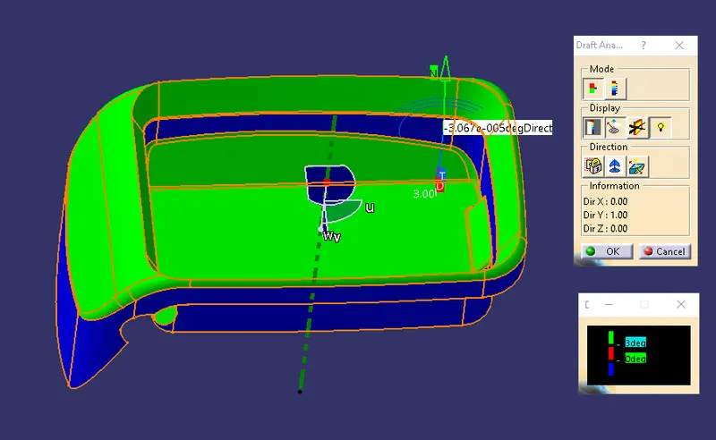
The above image shows the result on min of 3deg draft angle. Since the required draft value is 3 degrees as seen in the scale, the parts highlighted in green color have draft values greater than 3 degrees and the part and the faces highlighed in blude color have values lesser than -3 deg. Therefore with this analysis report we can observ that the min of 3 deg draft angle is not given for all the surface.
Image of complete Draft analysis and color scale variant
2.) Procedure for draft analysis on solid Body
Step-1- Choose the Feature Draft Analysis command from the Analysis toolbar marked in red box.
Insert-> Analysis-> Draft analysis
Step-2- Enable the compass feature in the Draft Analysis Toolbar as shown below.
Step-3- Place the compass on the required position and along the desired tooling direction on the part
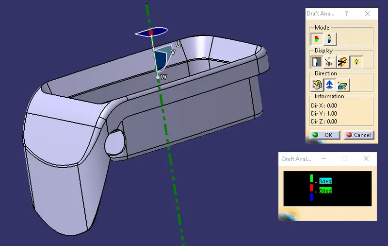
Step-4- Select the part on which draft analysis has to be performed. The part turns to the combination of colors present in the scale
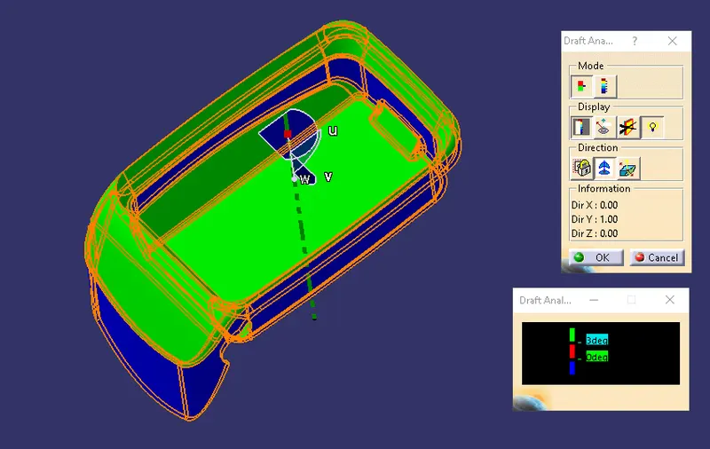
Step-5- Analyse the part with respect to the results obtained based on the scale, to identify the parts with draft feature. Quick analysis mode was chosen for the analysis.
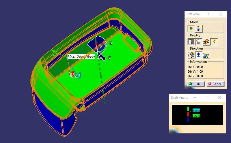
The above image shows the result on min of 3deg draft angle. Since the required draft value is 3 degrees as seen in the scale, the parts highlighted in green color have draft values greater than 3 degrees and the part and the faces highlighed in blude color have values lesser than -3 deg. Therefore with this analysis report we can observ that the min of 3 deg draft angle is not given for all the faces in the solid.
Image of complete Draft analysis and color scale variant
3.) Creation of Class-B Surface
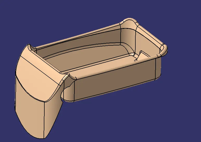
- Consider the thickness of the component as 2.5 mm. Now we need to create a B surface which will be similar to the A surface at an offset value of 2.5 mm.
- The B surface creation is performed using the surface operations in CATIA which is an offset from class A with dimension proportional to the thickness of the part.
- In coin holder the B surface is offset 2.5mm from the Class A input which is the thickness of the part.
- The B surface is an extrapolated surface compared to A surface and forms the bottom skin of the part.
4.) Creation of Class-C surface
Procedure
To create a Class C surface, first extract the boundaries of the Class A surface
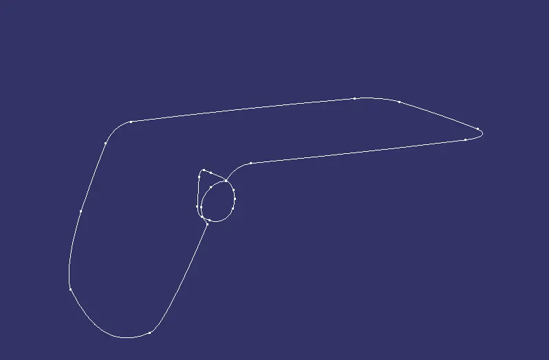
Now using the sweep option create the surface. To perform this operation, Go to the Toolbar > Sweep > Profile type > Line > Subtype > With draft direction > Guide curve 1 - (select the extracted boundaries) > Draft direction - (select the tooling axis) > angle and length as 3 deg and 20mm respectively and click ok.For holes extract the boundaries and use the sweep operation to form a surface.
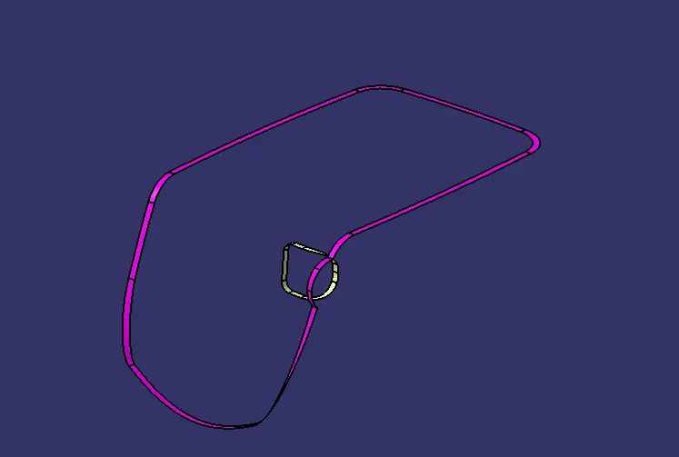
- Atlast Join the surfaces which are formed by using sweep command to form a Class C surface.
- After creation of Class A, Class B and Class C surfaces, we need to join Class A and Class C surface to form a new surface. Then trim the joined surface with Class B surface to form the final required surface.
- Now using the close surface option from part workbench to convert the surface body to part body.
5. Creating the solid model
- The final step included the conversion of the surface model into a solid model
- Using the Close surface tool in the part workbench, the surface model was successfully converted into a solid model
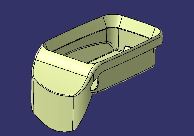
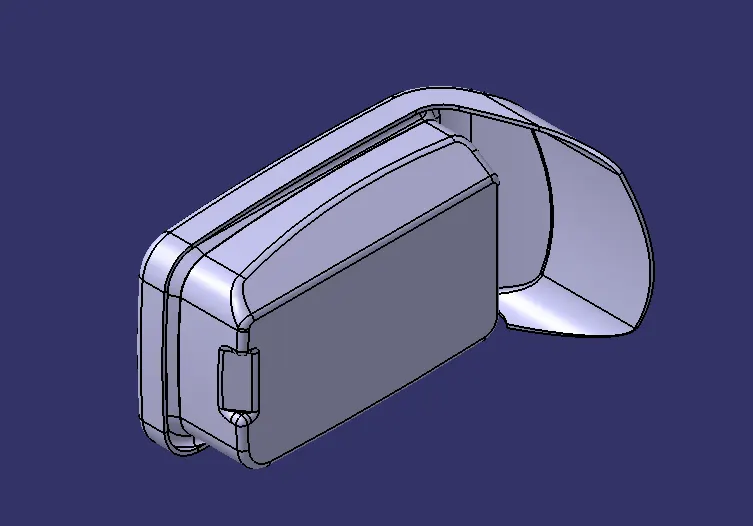
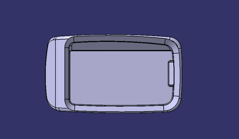
Screenshots of the solid model with the proper color code of the draft angle in various orientations (Isometric, Front, Side, and Top View)
Isometric View
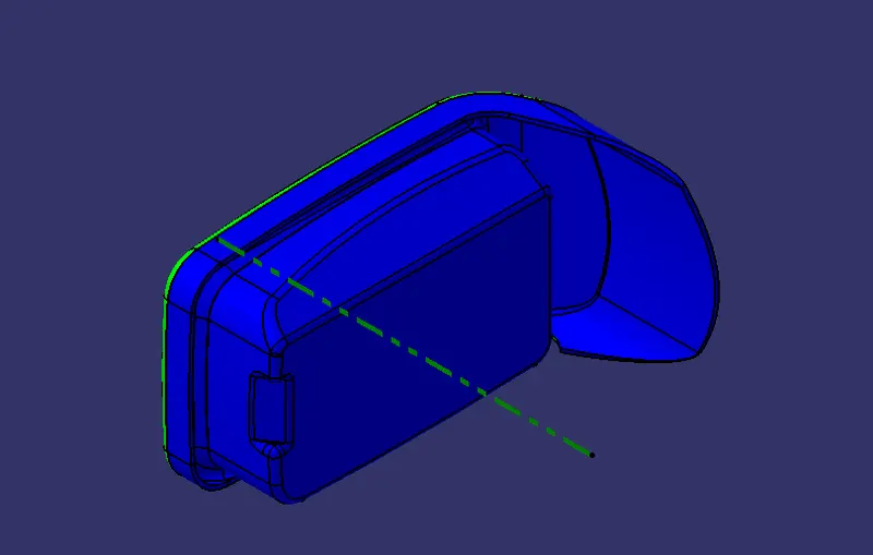
Front view
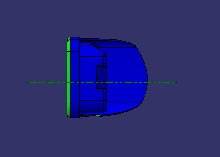
Side view
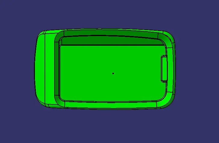
Top View
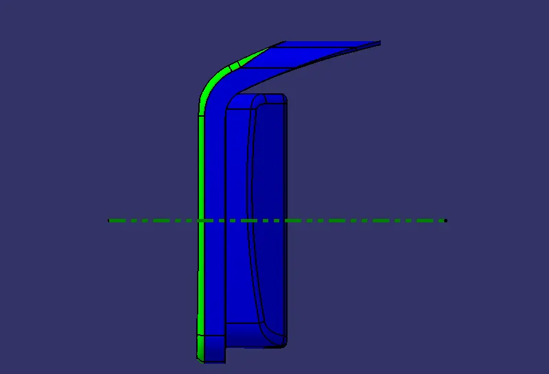
Different views of the Solid body
Isometric View
Front View
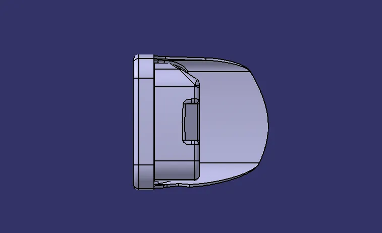
Top View
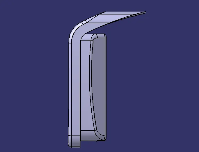
Side view
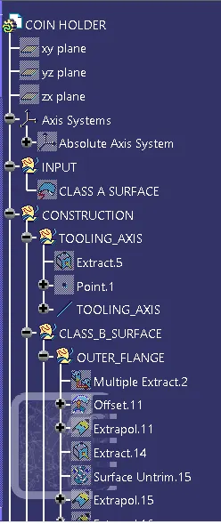
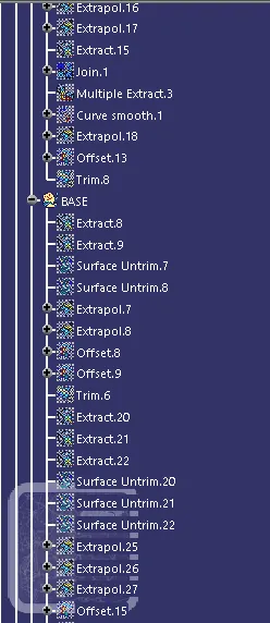
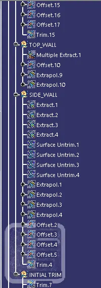
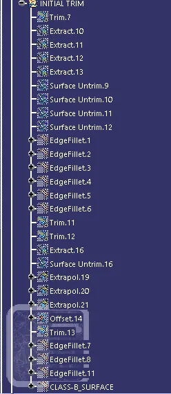
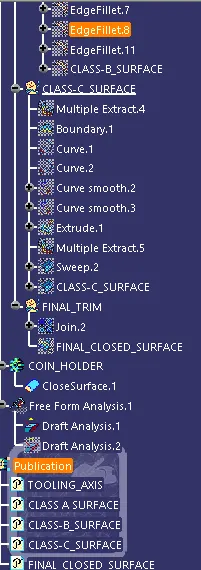
Tree Structure
CONCLUSION
From the given input surface( class- A) the respective Class b and c surafces are created and trimmed these surfaces to form a part bodt body having 2.5 mm thick and the draft analysis also done for the final component.