Design of an Electric Vehicle - Tesla Model 3 (PMDC motor)
OBJECTIVES:
- Design and simulate the Tesla Model 3 Standard Range RWD that uses a PMDC motor
Introduction
Earth is heading for a disaster. Humanity is having a material and irreversible impact on Earth - we've destroyed half of the world's forests and will soon wipe out most of the rest. The human and economic consequences of such changes will make Covid-19 look like an irrelevance of the 21st century.
Due to such activities, every year this planet's temperature is rising due to global warming, which is a direct consequence of the release of harmful gases such as carbon dioxide. An enormous amount of carbon dioxide is released from the cars we drive. One of the most significant ways of preserving our planet such that it remains livable for our future generation is to minimalize this release of `CO_2`. Powering vehicles through hybrid technology, going all electric or through alternate sources (such as hydrogen) is an excellent way of fighting climate change. Aren't we responsible to preserve the planet that we have constantly destroyed since the beginning of time? Here are a few consequences that have already happened, and its only going to get worse unless we start doing our part.
- Texas power grid failure 2021: it is a misunderstanding that climate change only refers to the earth getting warmer each other. This freak snowstorm in Texas may not seem like a harbinger of global warming, but a growing body of research links climate change with the occurrence of the so-called polar vortex. Scientists say warming in the Arctic, where temperatures are rising faster than anywhere else on the planet, may be weakening the jet stream that typically keeps cold air deep in the northern hemisphere. A weakened jet stream allows freezing air to drift down to lower latitudes, hence affecting areas like Texas which is among the lowest (in terms of latitudes) points in the US.
- Near-record melting of Arctic sea ice 2019: With the ice gone, the sun’s energy will instead be absorbed by the ocean. Losing the ice will be equivalent of adding 25 years’ worth of greenhouse gas emissions at the current rate humans are burning fossil fuels.
- Australia's apocalyptic fire season 2019: The record heat and dryness created some of the most apocalyptic early-season fire activity ever witnessed in the country, with at least 21 people killed, 15 million acres burned, and 3500 structures destroyed. Thousands of people had to flee to the beach to avoid incineration and be given supplies and evacuated by military ships and aircraft.
For more - https://climate.nasa.gov/effects/
Electric vehicles aren't fully clean either because of the pollution generated by the mining process of batteries and the facilities to process them. In addition, the electricity generated to power these vehicles currently coming from the grid is from non-renewable resources like coal and natural gas. However, they are still a lot cleaner than Internal Combustion Engine cars that still hold an overwhelming majority of the market, and this is what needs to change. The transition to clean and sustainable energy needs to be accelerated.
This project presents a MATLAB/SIMULINK model of an entire electric vehicle (EV). I have decided to model the Tesla Model 3 and simulate its characteristics for this project. The Tesla Model 3 became the world's all-time best selling EV in 2020, so it was a great option for this project as there is a lot of information and data available in addition to the fact that this was a brilliant and inspiring invention from Tesla.
The main components of an EV are:
- Battery
- Motor controller/Power converter
- Motor/Generator
- Vehicle body (including transmission, wheels)
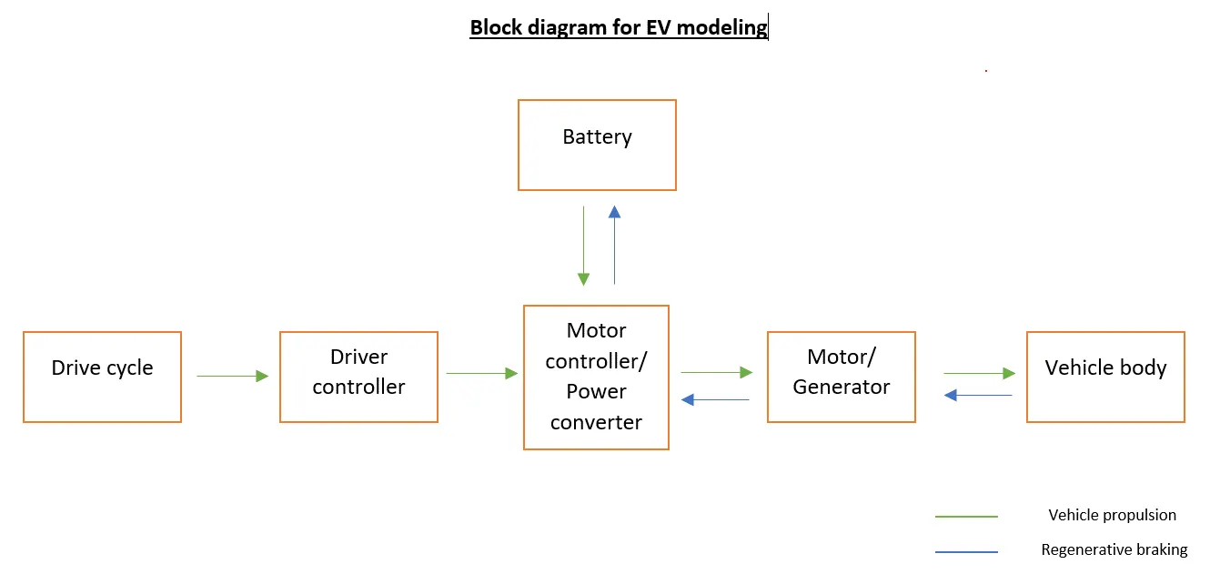
This is how an EV is typically modelled. A battery provides electrical power to the motor, which converts it to mechanical power and powers the vehicle. However, if the battery is directly connected to the motor, the vehicle would be running at constant speed as there is no control. A motor controller is a power converter that bridges this gap and controls the speed and voltage provided to the motor, so the vehicle performance can be controlled.
To run a simulation, a reference always needs to be provided to the system so that it knows what it is working towards. Without a reference drive cycle, the system would not know when to accelerate, brake, or stop the vehicle, and hence the performance of the entire system cannot be evaluated as we will never know how effectively everything is working.
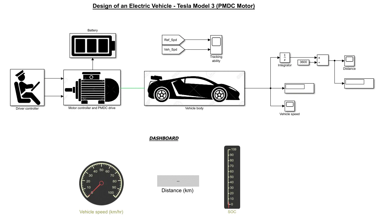
System level configuration:
(Note - all numbers used are actual parameters of the Tesla Model 3 Standard Range RWD unless mentioned otherwise)
1) Vehicle body:
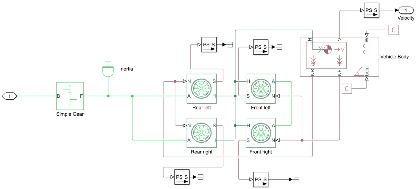
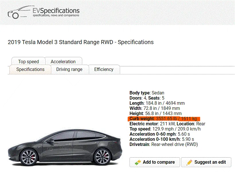
| Vehicle body of Tesla Model 3 | |
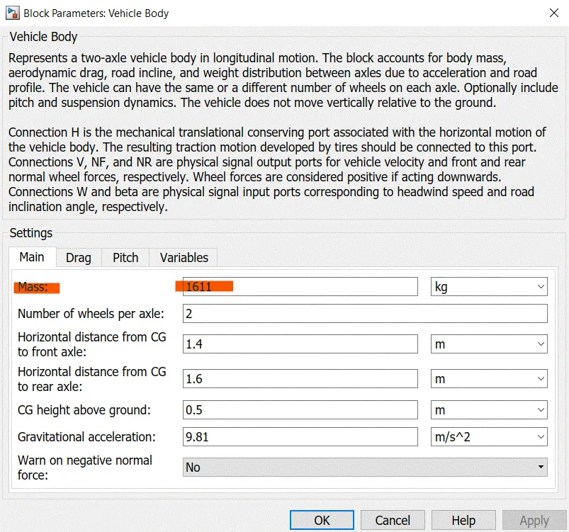
| Mass | 1611kg |
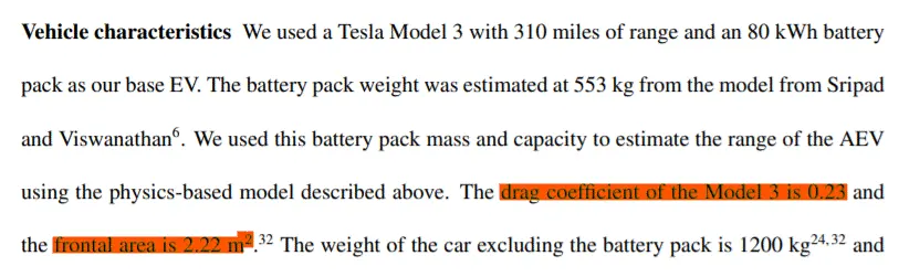
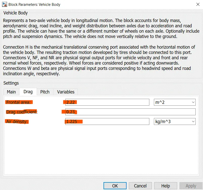
| Frontal area | 2.22m2 |
| Drag coefficient | 0.23 |
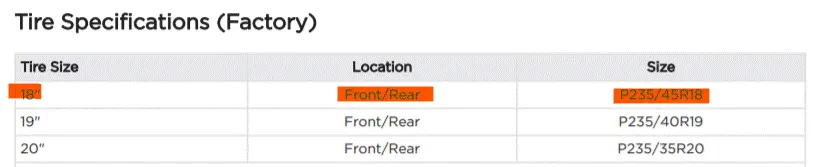
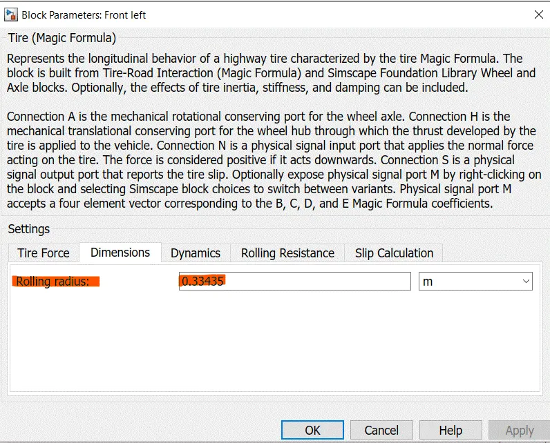
| Tire radius | 0.33435 (calculated from tire specs) |
| Coefficient of rolling resistance | 0.01 |
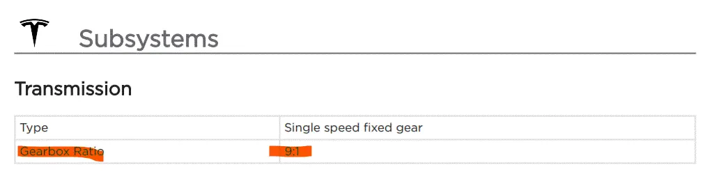
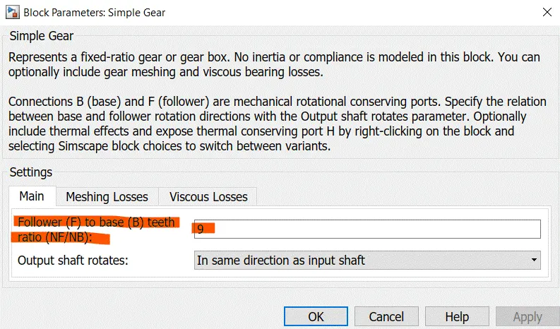
| Gear ratio | 9:1 |
2) Battery:
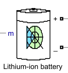


| Battery of Tesla Model 3 | |
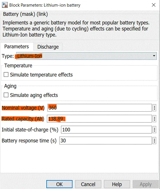
| Type | Lithium-ion |
| Nominal voltage | 360V |
| Capacity | 50kWh |
| Rated capacity (Ah) | 50*1000/360 =138.89Ah |
3) DC Motor:
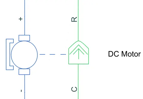
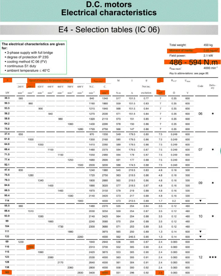
The motor needs to be chosen according to the vehicle's rated power and rated torque & the battery's nominal voltage:
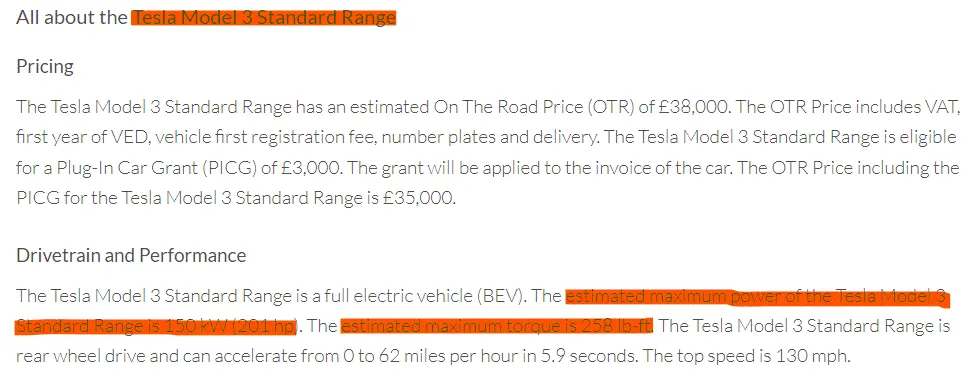
| Performance parameters of Tesla Model 3 | |
| Rated power | 150kW (201 hp) |
| Peak power | 211kW |
| Rated torque | 350Nm (258 lb-ft) |
| Peak torque | 450Nm |
Note: The Tesla Model 3 actually uses Interior Permanent Magnet (IPM) synchronous motor, and unfortunately the data needed on it was unavailable. Thus, a DC motor had to be opted for simplicity. DC motor data for 360V (nominal voltage of battery of Tesla Model 3) was not found, thus the closest possible voltage value (400V) was used.
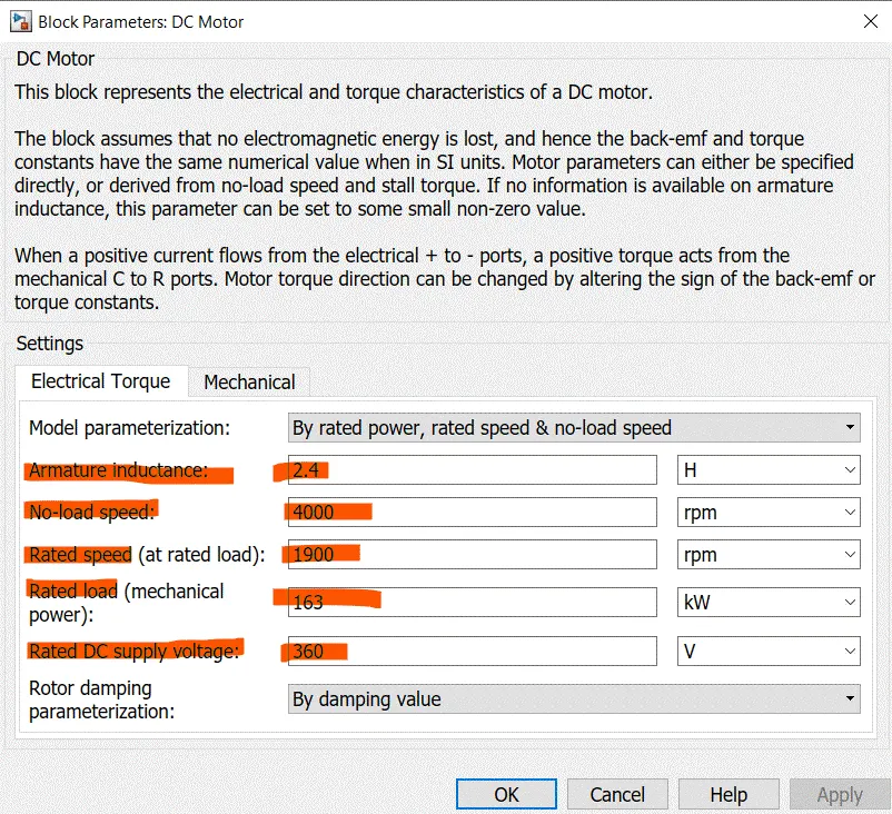
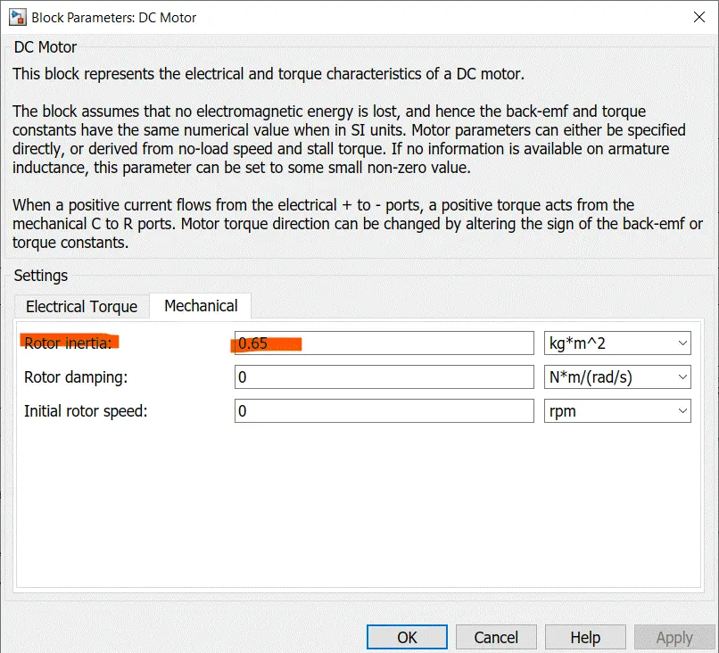
4) Motor controller:
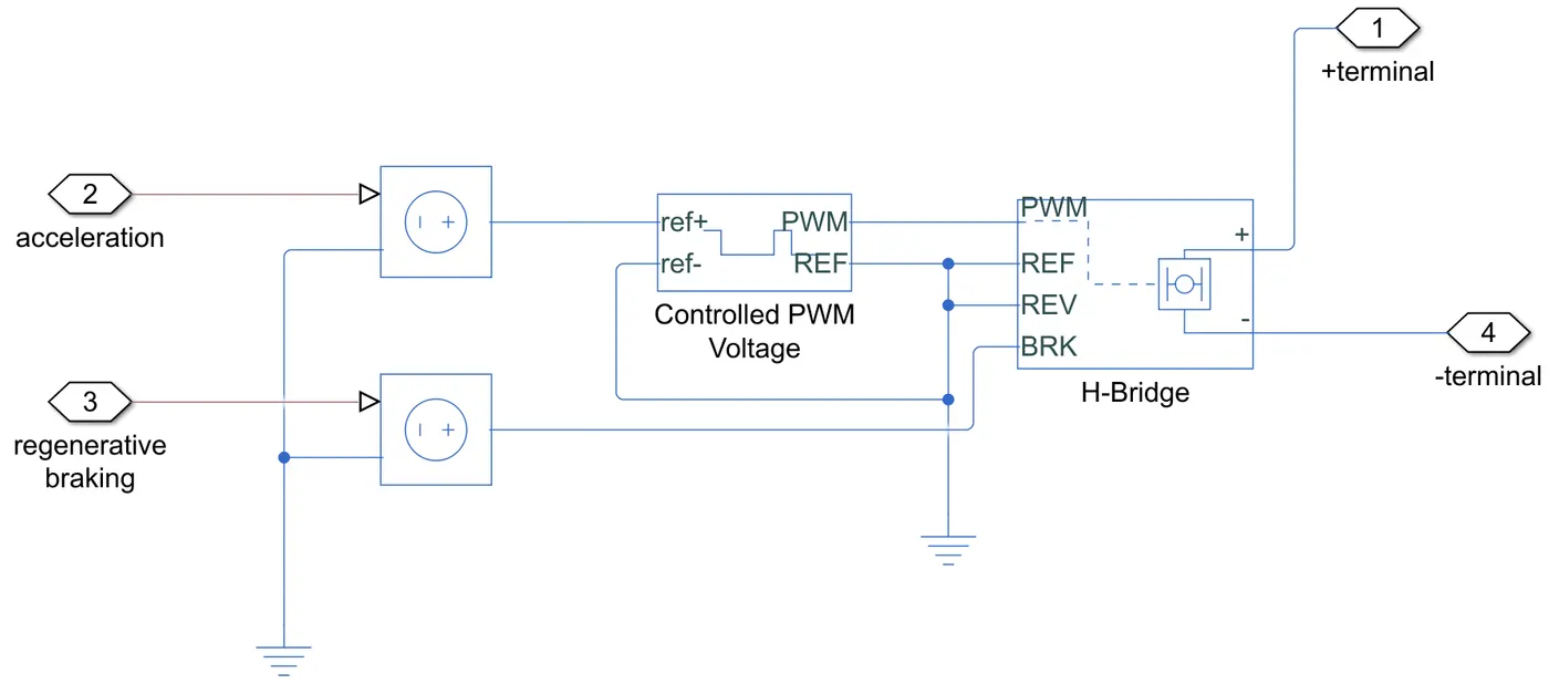
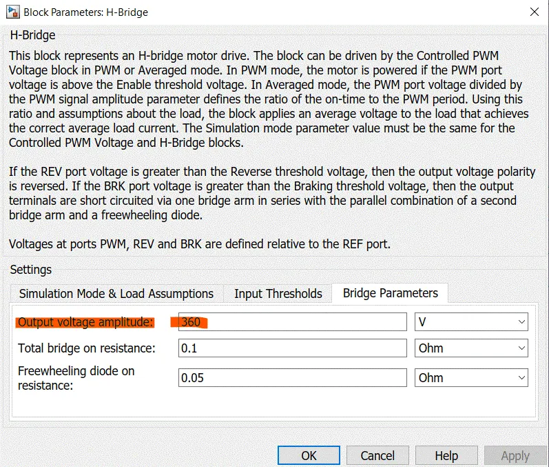
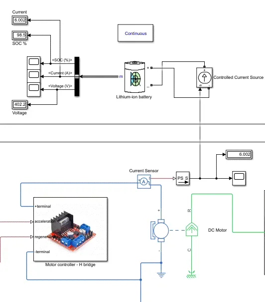
- The H-bridge motor controller is a power converter that receives supply from a PWM voltage block. It controls the power according to the vehicle performance requirements and transmits it to the motor (as can be seen by the positive and negative voltage terminal)
- If the accelerator signal is given, the motor controller converts that signal into the appropriate voltage needed to supply to the motor (refer to H-bridge configuration above), and likewise happens with the brake signal. In addition, when the brake signal is given, this is a power converter with regenerative braking, which means that it takes current back from the motor (which is acting like a generator), controls it appropriately as to not destroy the battery with a sudden insurge of current, and transfers it to the battery to charge it.
- Normally, an external battery is what supplies the electrical energy to this motor controller, however to avoid a longer simulation running time and complexity, this controller has been built with an internal supply which can power the motor.
- The battery subsystem has been added nevertheless (refer to the third figure above) to demonstrate what would happen if the power supply was external in the form of a battery (which is the case in reality). However, in this case, the battery is only at the receiving end of the current as is seen. The current source indicates to the battery how much current is required by the motor and the battery discharges accordingly, giving us the results of what would happen in reality.
5) Driver controller:
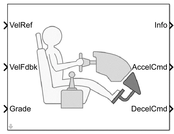
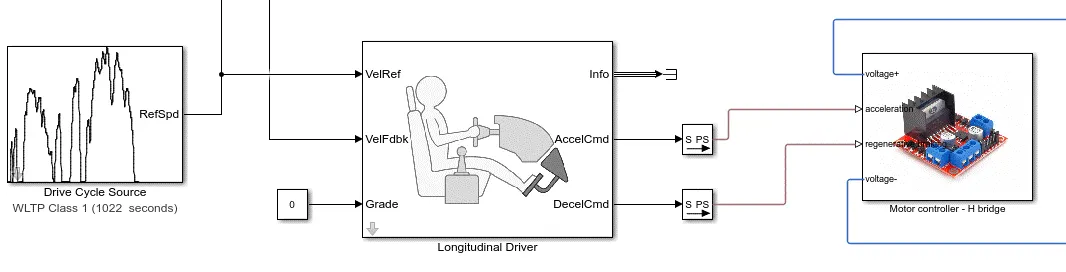
- This is a driver controller block which is given a reference speed via a drive cycle as is evident. Simultaneously, this PID controller block takes the speed the vehicle is actually travelling at (due to its parameters) through a feedback loop and compares it with the drive cycle.
- If at any point in time the vehicle is travelling at a speed higher than the reference drive cycle, the driver controller hits the brakes to decelerate the vehicle. If its the other way around, the throttle is pressed to accelerate. Both commands are transmitted to the motor, and thus to the vehicle, through the H-bridge motor controller .
- The job of this block is to minimize the difference between the input it has been given and the speed the vehicle is actually travelling at.
Results:
Vehicle propulsion:
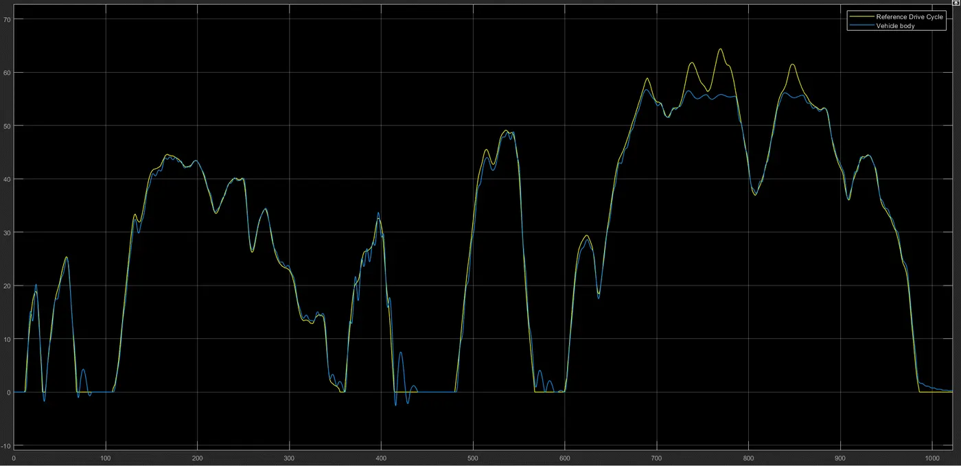
- As is evident, the vehicle has been able to meet the drive cycle quite closely with good accuracy barring the 50 seconds between 700-800s. This is due to the insufficient no-load speed of the DC motor chosen. A slightly higher no-load speed would be sufficient to meet the current drive cycle requirements.
- The Tesla Model 3 Standard Range RWD's top speed is actually 209km/h, however with this simulation the top speed is around 55km/h only. The reason is due to the difference in motor used. The Tesla Model 3 uses Interior Permanent Magnet (IPM) synchronous motor, and unfortunately the data needed on it was unavailable. Thus, a DC motor had to be opted for simplicity in simulation.
SOC:
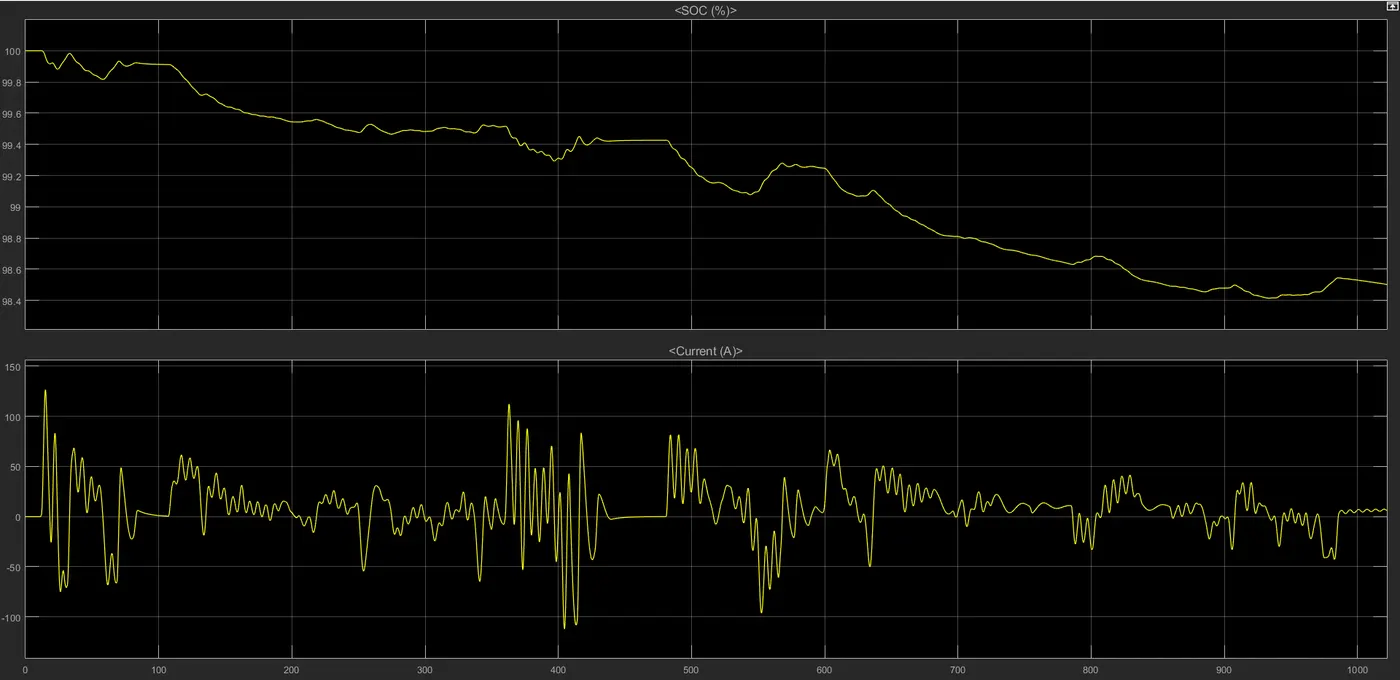
- The SOC of the battery has only reduced from 100% to 98.5%. The main reasons are that the Tesla Model 3's rated battery capacity is about 139Ah, which is considered high. Higher ampere-hours rating results in more power and more performance, allowing the battery to work for a longer time on a full charge as compared to the cells with lower ampere-hours. Moreover, the drive cycle was only 17 minutes long with a lot of deceleration curves, which consistently allowed the battery to recharge through regenerative braking.
Distance travelled:
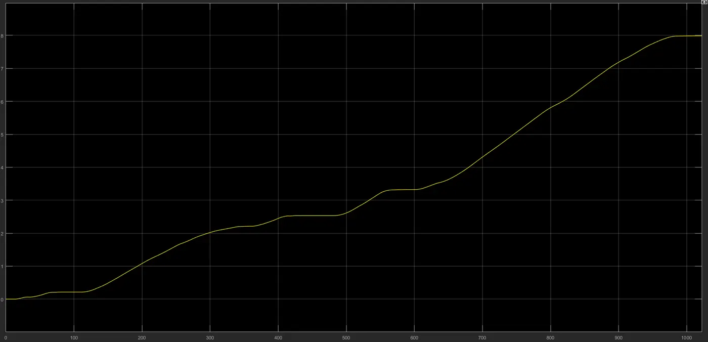
- The total distance travelled is about 8km in about 17 minutes, which is an average speed of about 30km/h
Conclusion:
This is a simulation using as close to the identical data of Tesla Model 3 as was possible (barring the difference in motor used), as to evaluate the actual performance of the chosen vehicle as much as possible.