Design of an Electric Vehicle - Tesla Model 3
OBJECTIVES:
- Design and simulate the Tesla Model 3 Standard Range RWD that uses a PMSM motor
I've previously designed a Tesla Model 3 using a PMDC motor (here), even though in actuality the Tesla Model 3 uses an Interior Permanent Magnet Synchronous Motor (IPMSM). The fact that a PMDC motor and its control works completely differently to that of an IPMSM always urged me to explore a different combination. I wanted the model and simulation to resemble the Tesla Model 3 as closely as possible, and hence I learned how to model a PMSM motor.
Note: PMSM motors are classified into IPMSM and SPMSM, however I am still learning how to model a PMSM motor with that level of specificity. This project therefore models the Tesla Model 3 with a general PMSM motor.
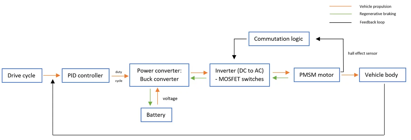
Above is a block diagram demonstrating how an EV with a PMSM motor is typically modelled. PMSM motors can be run by both sinusoidal voltages and trapezoidal voltages. Trapezoidal voltages are easier to produce because they consist of square waveforms, and transistors only need to be turned on and off to generate that kind of output. Sinusoidal voltages on the other hand need an extra encoder along with the hall effect sensor for accuracy, or field oriented control (FOC) needs to be implemented. This is a more complicated and computationally heavy method, but it comes with the advantage that torque output is smooth and constant. With trapezoidal commutations there is always a torque ripple at the start of each commutation, but the control is simpler. For automotive applications, PMSMs should be run by sinusoidal voltages because smooth and constant torque is desired in an EV, however, for the purpose of a simpler simulation, trapezoidal voltage is used to power the motor. When a PMSM motor has a trapezoidal back-emf, it is also known as a BLDC motor.
PMSM motors are powered by 3-phase AC; that's where the inverter comes into the picture. The battery pack generates a DC voltage which needs to be converted into a 3-phase square-like (trapezoidal) waveform. Generally, MOSFET switches in an inverter can handle a peak voltage of 100-150V, however, the battery pack produces a voltage of 360V. The buck converter takes into account the duty cycle from the PID controller and steps down the voltage accordingly for the inverter.
EXPANDED MODEL:
CONDENSED MODEL:
TRACTIVE FORCES:
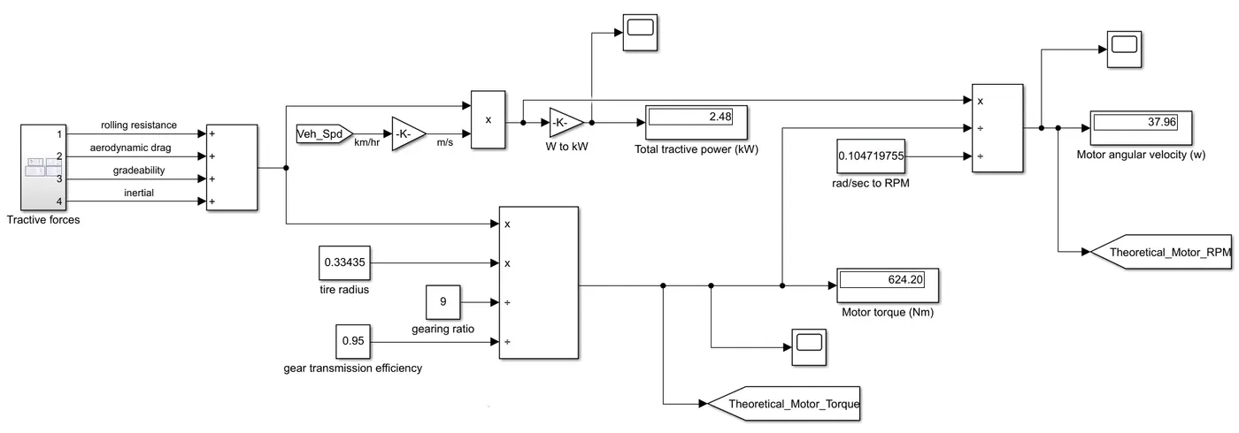
Governing equations:
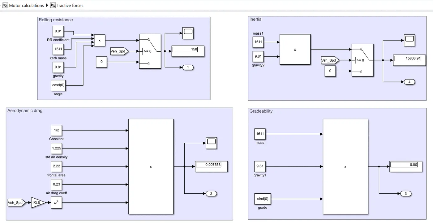
- Theoretical Tractive Power = `F*v`
- Theoretical Motor Torque = `(F*r)/(G*eta_g)`
- Theoretical Motor RPM `omega=(Power_(out))/(T*((2pi)/(60)))`
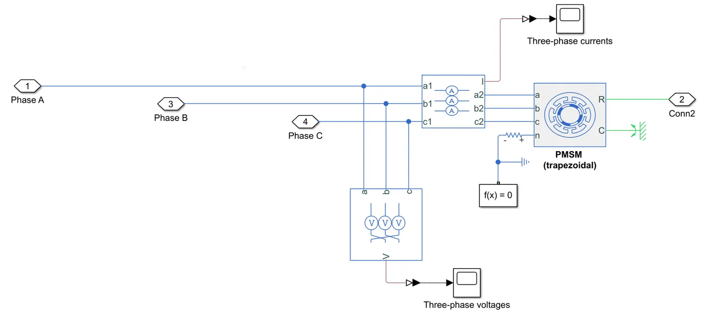
MOTOR:
MOTOR CONTROL:
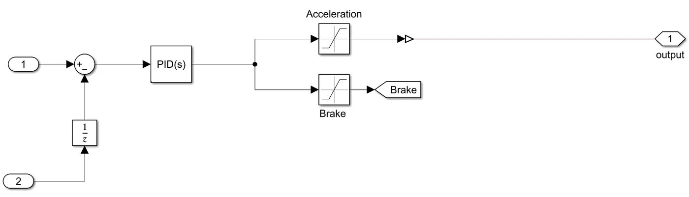
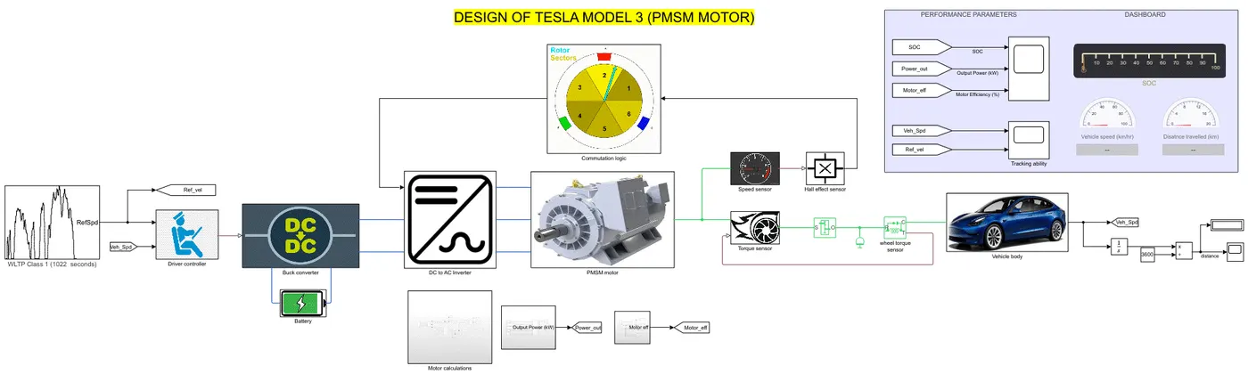
- The PID controller reduces the error between the reference speed and the actual vehicle speed, and accordingly gives the acceleration or brake command.
- The acceleration command translates into a duty cycle value while a brake command directly initiates a brake force on the wheels.
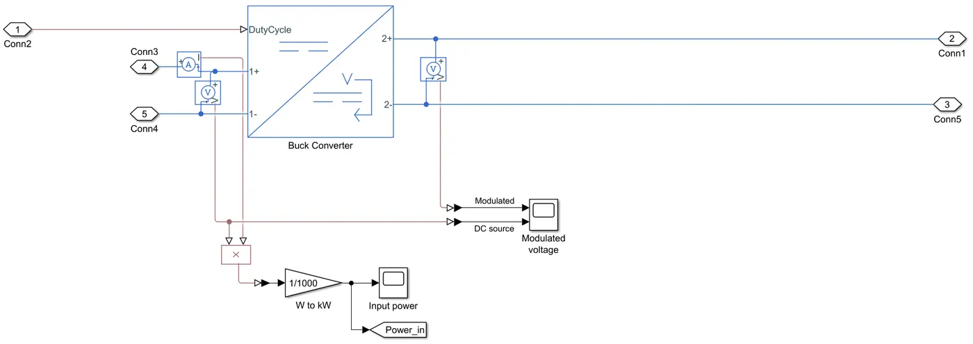
- The buck converter takes the duty cycle into account and modulates the voltage (provided by the battery) for the inverter to use.
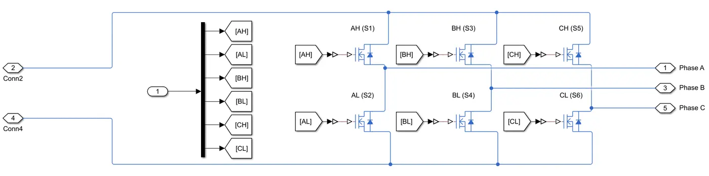
- The inverter translates the DC modulated voltage provided by the buck converter into 3-phase AC through the use of 6 MOSFET switches that turn on and off at a speed determined by the duty cycle.
OPERATION AND WORKING PRINCIPLE OF PMSM MOTOR (TRAPEZOIDAL COMMUTATION):
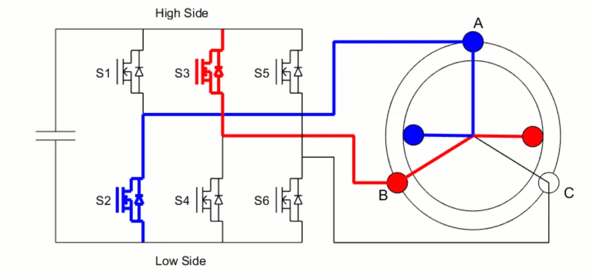
| Switches | S1 (AH) | S2 (AL) | S3 (BH) | S4 (BL) | S5 (CH) | S6 (CL) |
| Commutations | 1 | 0 | 0 | 0 | 0 | 1 |
| 0 | 0 | 1 | 0 | 0 | 1 | |
| 0 | 1 | 1 | 0 | 0 | 0 | |
| 0 | 1 | 0 | 0 | 1 | 0 | |
| 0 | 0 | 0 | 1 | 1 | 0 | |
| 1 | 0 | 0 | 1 | 0 | 0 |
Note: H = high side = North pole, L = low side = South pole; AH turned on would mean A is acting as the North pole.
The motor consists of a permanent magnet (the red and blue poles rotating in the figure) as part of the rotor, and coil windings (3 sets of windings) as part of the stator, which can be referred to as A, B, and C, as depicted in the figure above.
A DC supply is given to a set of coil combinations (S1 and S6 for instance), energizing them and making them an electromagnet in a magnetic arena. The operation is a simple interaction between the permanent magnet and the electromagnet A/B/C, which exerts a force on the rotor, thereby rotating it to produce a torque. There are 6 sets of combinations as presented in the table above which energize different sets of coils to keep the rotor rotating.
Limitations of PMSM motor with trapezoidal commutation instead of sinusoidal commutation:
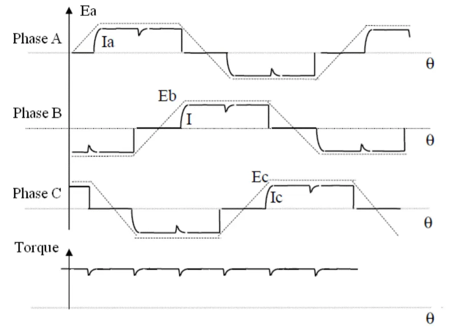
The back-emf (Ea, Eb, Ec) shape depends on how the coil windings are wounded and designed to be in the stator. For best performance and highest efficiency, it is recommended that the drive current match the back-emf waveform. To do this, square-like waveforms need to be produced through DC current and turning transistors on and off, as is seen in Ia, Ib, and Ic above.
In practice, when commutations change and there is a shift in phase current (from AH,CL to BH, CL for instance), the current cannot be established in the coil instantaneously. The magnetic fields in the previous phases collapse and are built in the newly energized phases. This is why there is a torque ripple at the start of every commutation (since torque is proportional to current), as for a short time period there is that dip in torque while the coils are transitioning.
Increasing the inductance in the motor will oppose this tiny stoppage in current and reduce the ripple, but for a more concrete solution, sinusoidal drive currents with encoders or FOC will need to be used. That will give a smooth, constant torque, which is certainly desired for automotive applications. However, as mentioned previously, their control is complex and expensive, thus using a trapezoidal input is the trade off between performance requirements and control complexity & cost.
How does the inverter know which combination of switches to turn on and off?
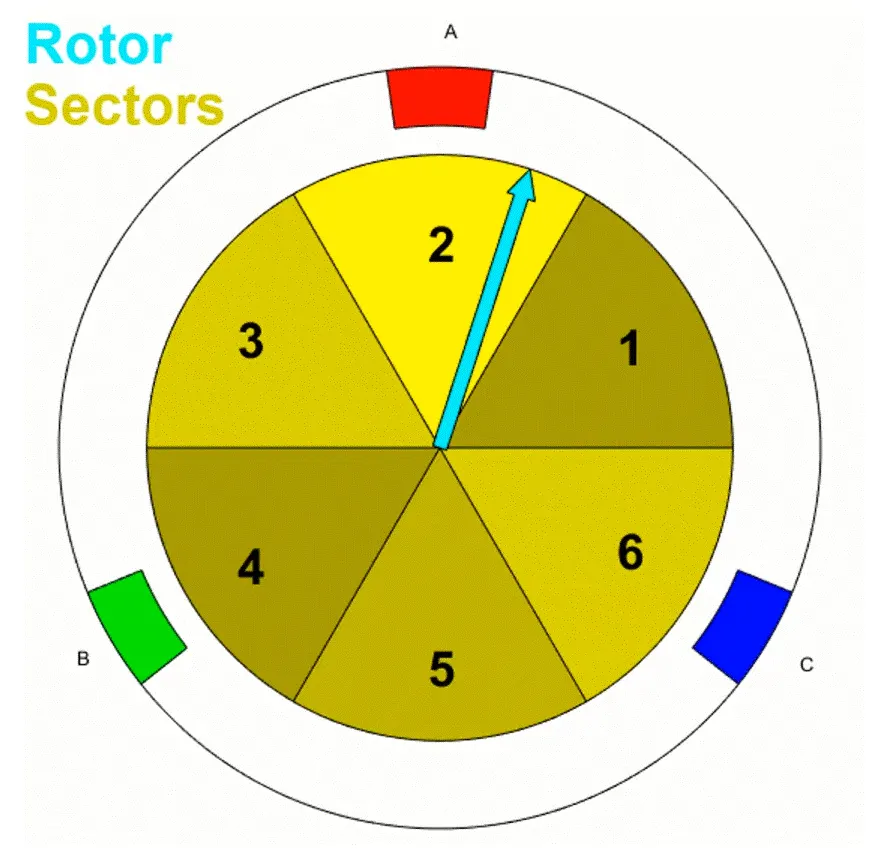
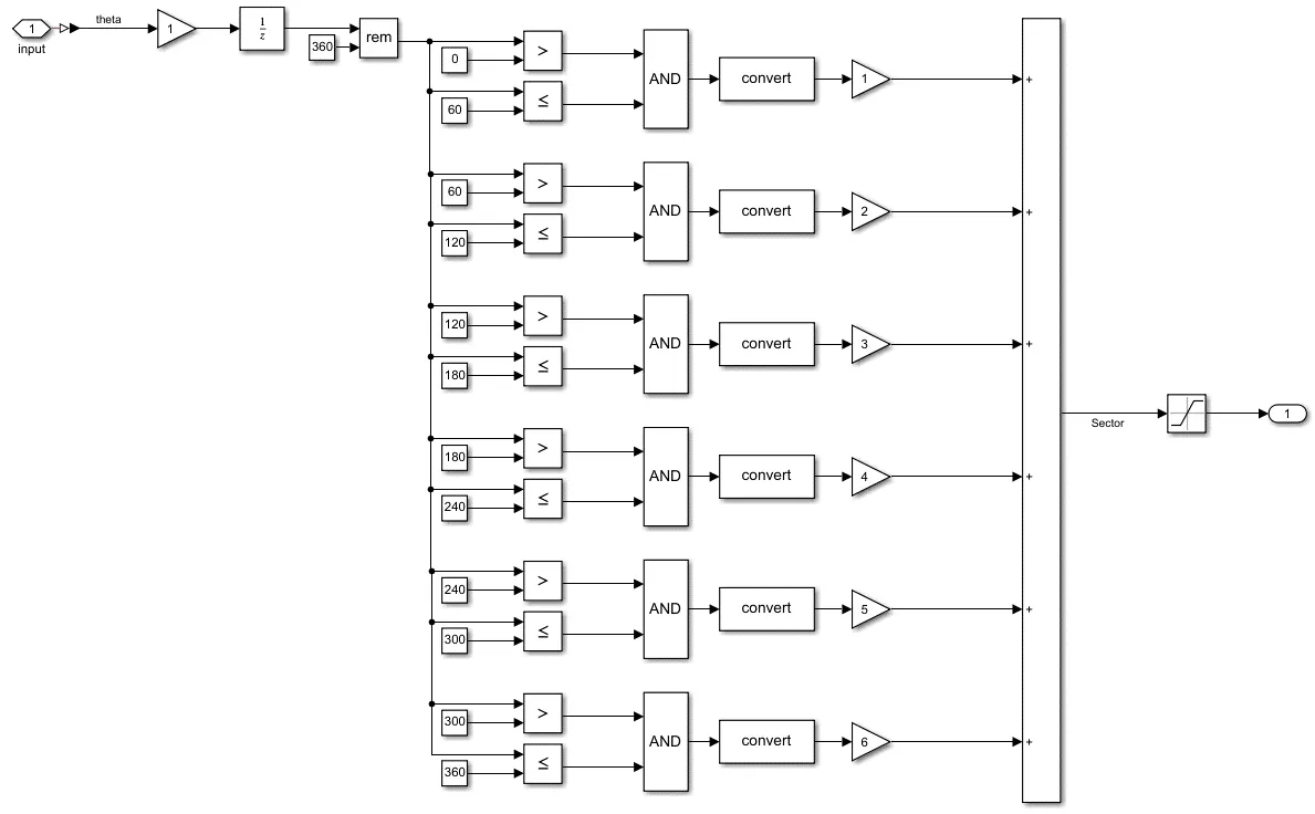
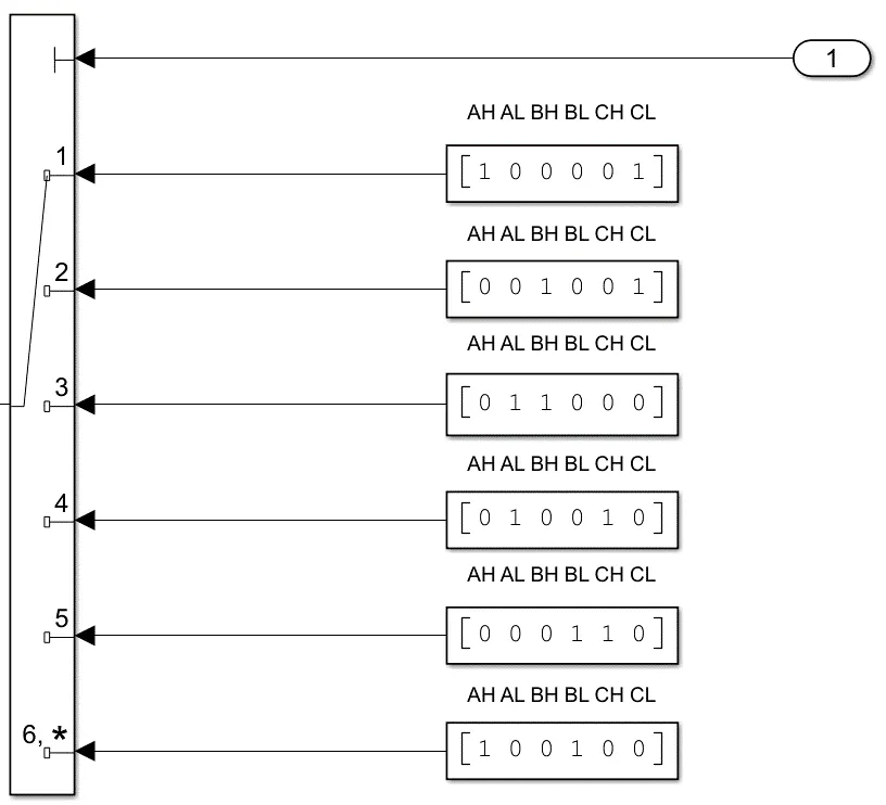
Referring to the block diagram at the beginning of the report, the motor and the inverter are connected in a feedback loop. Hall effect sensors determine the magnetic field around each phase to determine which sector the rotors are currently in by sending a high or low signal to indicate which rotor pole (N or S) is passing over them, and accordingly select which two phases out of A, B, and C need to be energized. For example, in the rotor sector figure above, lets assume the blue arrow is the N rotor magnet. This one is in sector 2, hence its counterpart, the S rotor magnet, is in sector 5. Assuming a counterclockwise rotation, the N rotor magnet needs to move towards coil B, while S rotor magnet will move towards coil C. Coil B therefore needs to be a South pole (BL) while Coil C needs to be a North pole (CH). Referring to the table above, that would be commutation #5, where BL and CH are energized while the others are open. Through 3 hall effect sensors, 6 commutations performed every 60 degrees complete an electrical cycle of 360 degrees and keep the rotor rotating.
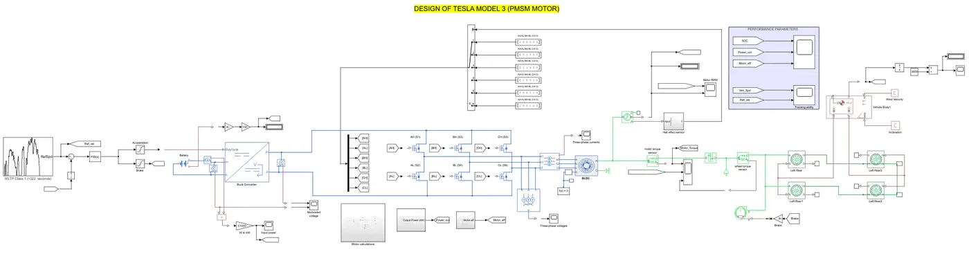
For simulation purposes, one way to model the hall sensor is shown on the figures in the second row above. Angular position through a rotational motion sensor connected to the motor will provide information on the position of the N and S pole of the permanent magnets. For example, if the N pole is anywhere between its starting point and 60 degrees, the sensor will determine that it is in sector 1 and then accordingly commutation logic #1 will be applied to excite the pair of coil windings AH and CL.
SENSORS:
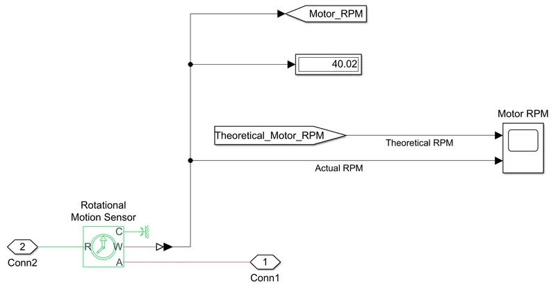
- Hall effect sensor described previously takes the angular position of the motor from port 'A' of the motion sensor
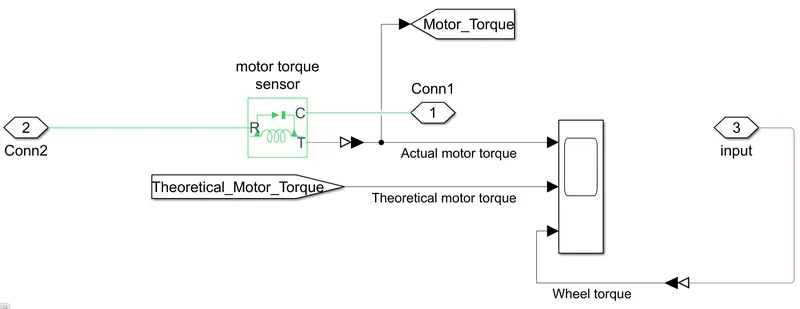
- Speed and Torque sensors are attached to the DC motor to compare the actual performance of the motor with the theoretical estimation (refer to Tractive Forces and Gooverning equations section above)
RESULTS:
Source voltage (battery) vs Modulated voltage:
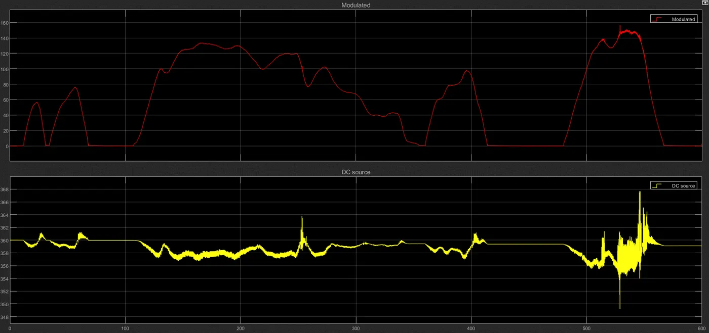
- The battery generates a constant voltage of 350-360V, and the buck converter modulates that to 0-150V as per the requirements of the motor.
Motor RPM:
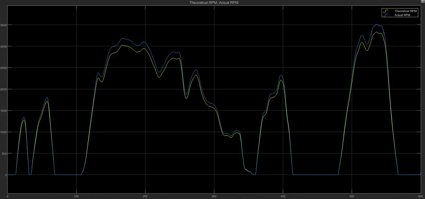
- The curves being identical in nature and the difference between theoretical and actual RPM being very little demonstrates the correct working of the model and the motor.
Performance parameters (1):
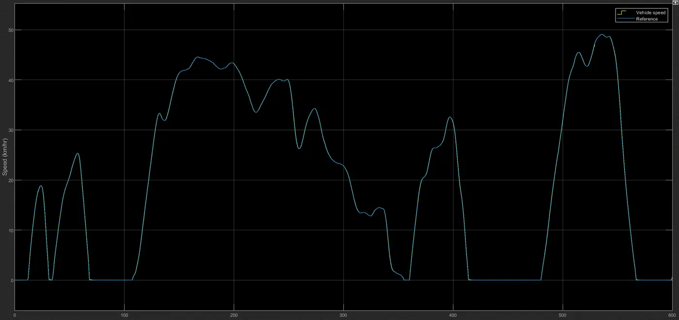
- As is evident, the vehicle tracks the reference drive cycle perfectly. This results in optimized performance and excellent resource management. With different drive cycles the PID controller needs to be tuned differently.
Performance parameters (2):
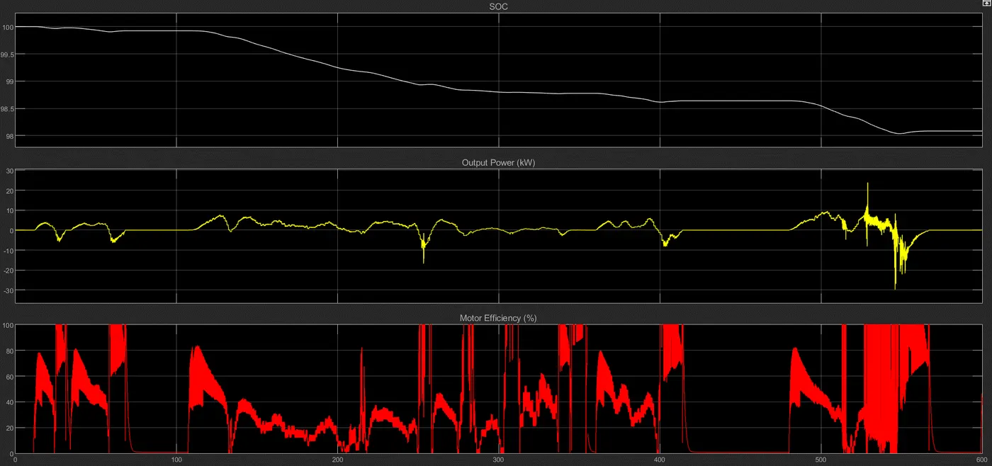
- SOC depletes from 100 to 98% in about 10 minutes. Would've been lesser had there been regenerative braking modelled, as energy would've been recovered back to charge the battery.
- Average output power for this drive cycle is lesser than 10kW, apart from a few spikes towards the end
- Motor efficiency, although very unstable and fluctuating, averages between 40 - 80%. Current fluctuations need to be reduced.
How can this project be improved further?
- Regenerative braking was not modelled in this project. I am able to model it when a PMDC motor is used, but still trying to figure out how to do it with a PMSM motor. Without this the project certainly feels incomplete since regenerative braking is an engineering marvel that was introduced with HEVs and EVs.
- PID controller can be tuned further to optimize vehicle performance, such as lower peak power, reduced fluctuations in voltage and current, lesser energy consumption from battery, etc.
- Oseiasdepaula FerreiraHi, It is possible to download this simulation?
- Parth MaheshwariHello, would you like some help in building this? I prefer not to make my simulation and files public, but am happy to guide you if you'd like that.
- Manikantakavin343I am stuck with break part , Could you pls tell me the saturation block upper limit and lower limit and wat is in the gain block for the break input.