Design and Modelling of an E-Rickshaw
OBJECTIVES:
- Design and simulate an E-rickshaw in MATLAB/SIMULINK
- For any three standard driving cycles show energy consumption, temperature rise of motor & motor controller
- Run the vehicle at constant speed of 45 kmph for 100km (Wide Open Throttle) and analyse results
INTRODUCTION:
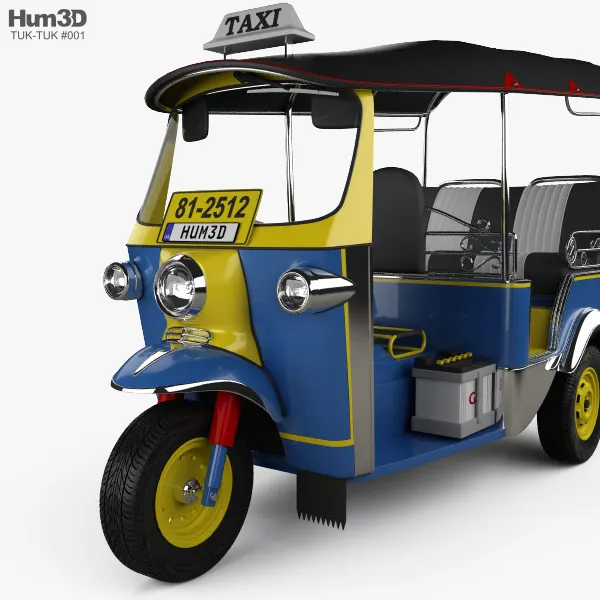
Conventional, diesel/petrol driven rickshaws are not used as a medium of transport in most countries in the world. However, they have emerged as such a great option in bustling, busy cities where traffic and mobility are huge inconveniences. They are common in countries with tropical climates, and in developing nations since they are relatively inexpensive to use.
They exist in Egypt and South Africa, are the leading short distance travel solution in India, a huge attraction for tourists in Thailand, and more.
Undoubtedly, E-rickshaws can be a great option for public transport in busy and polluted cities, as it will not just reduce traffic but can also reduce pollution levels significantly. However, factors such as insufficient charging facilities, low driving range, battery replacement/disposal concerns make it a challenging option. In the future, hybridized E-rickshaws with an effective Battery-Ultracapacitor combination will allow to accelerate the process of electrification in developing countries to make a positive impact to climate change, as going completely electric is decades down the line for most countries.
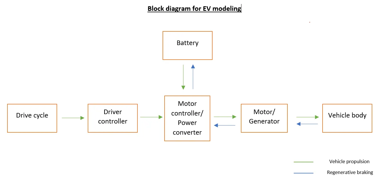
This is how an EV is typically modelled. A battery provides electrical power to the motor, which converts it to mechanical power and powers the vehicle. However, if the battery is directly connected to the motor, the vehicle would be running at constant speed as there is no control. A power converter is that controller which bridges this gap and controls the speed and voltage provided to the motor, so the vehicle performance can be controlled.
To run a simulation, a reference always needs to be provided to the system so that it knows what it is working towards. Without a reference drive cycle, the system would not know when to accelerate, brake, or stop the vehicle, and hence the performance of the entire system cannot be evaluated as we will never know how effectively everything is working.
EXPANDED MODEL:
CONDENSED MODEL:
TRACTIVE FORCES:
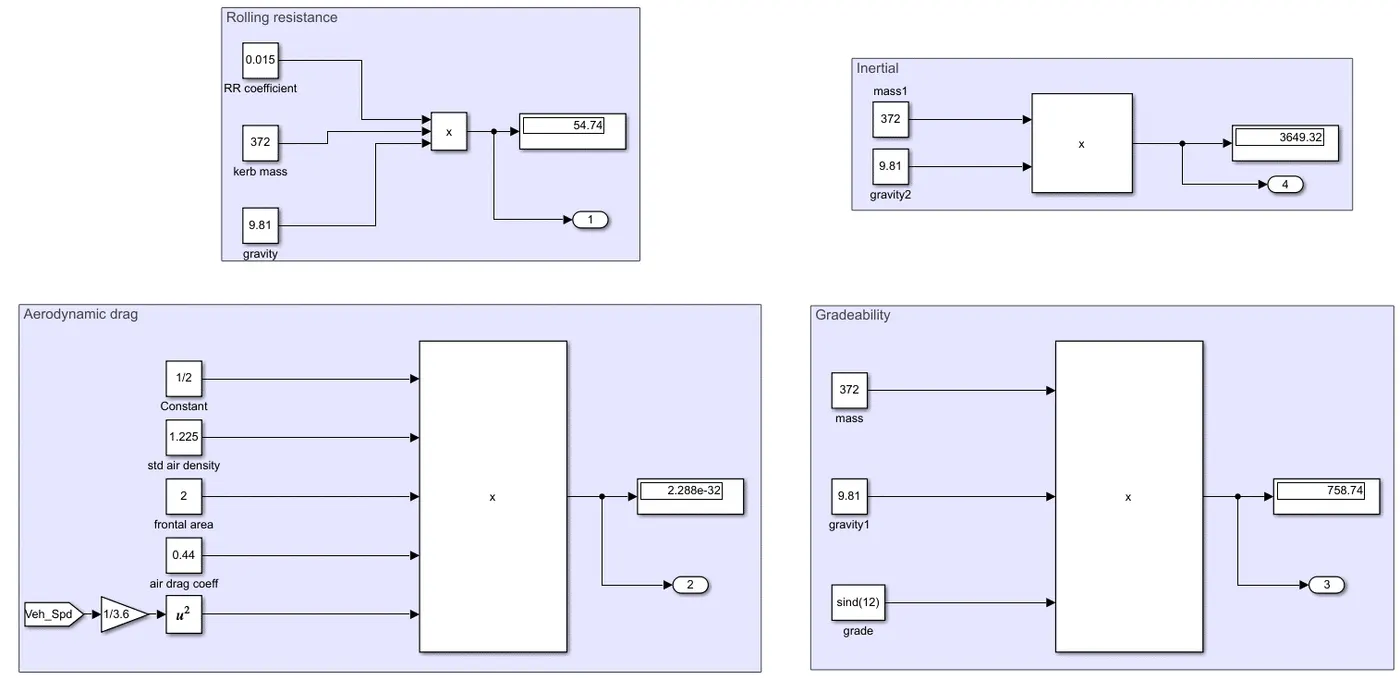
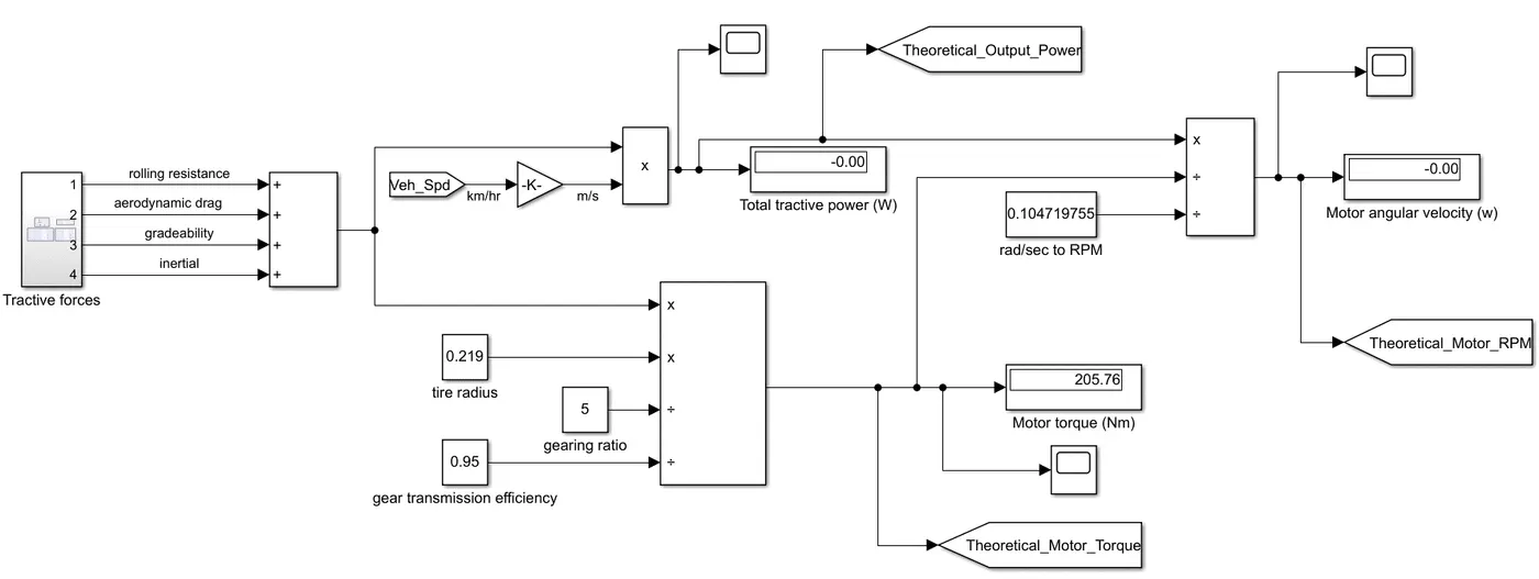
Equations:
- Theoretical Tractive Power = `F*v`
- Theoretical Motor Torque = `(F*r)/(G*eta_g)`
- Theoretical Motor RPM `omega=(Power_(out))/(T*((2pi)/(60)))`
MOTOR SELECTION: these are the chosen drive cycles and their respective vehicle performance. These are the most important parameters to consider when choosing an electric motor.
| Drive cycle | Peak power (kW) | Peak motor torque (Nm) | Peak motor speed (RPM) |
| NYCC (598 sec) | 14 | 100 | <3000 |
| WLTP Class 1 (1022 sec) | 5 | 25 | <4000 |
| Braunschweig City (1740 sec) | 12 | 90 | 3500 |
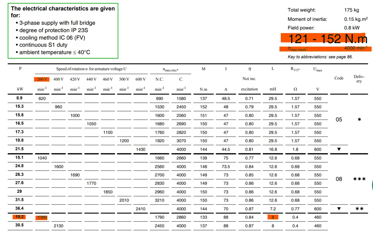
Type of motor: Permanent Magnet DC Brushed-type
Peak power: 19.2kW
Peak torque: 121 - 152Nm
Max motor speed: 4000 RPM
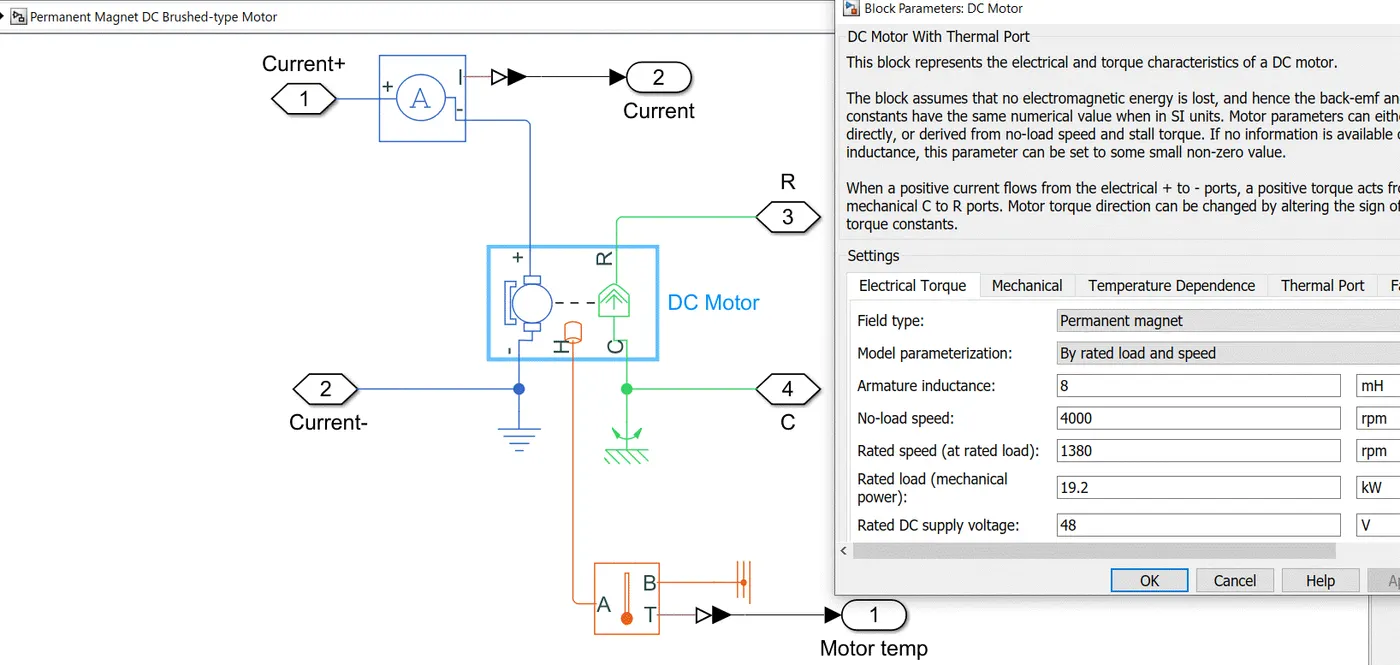
References used to model components:
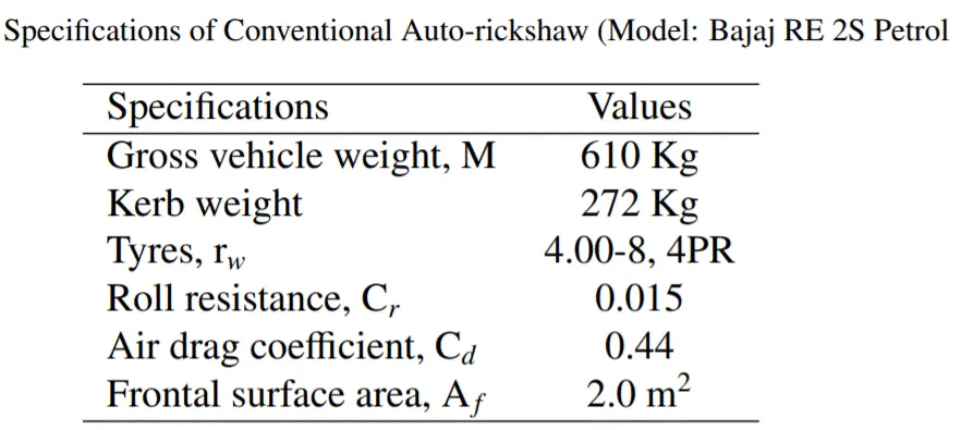
1) Vehicle specifications: https://www.astesj.com/publications/ASTESJ_0505141.pdf
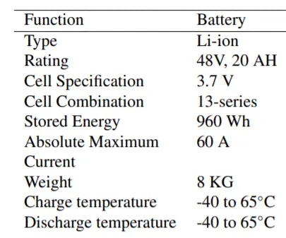
2) Battery datasheet: https://5.imimg.com/data5/CJ/WZ/TL/SELLER-16128898/48v-20ah-li-ion-battery-pack-for-electric-bike-and-scooty.pdf
MOTOR CONTROLLER:
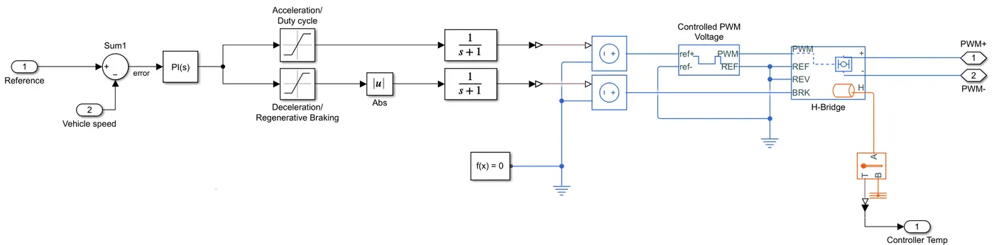
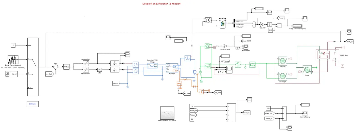
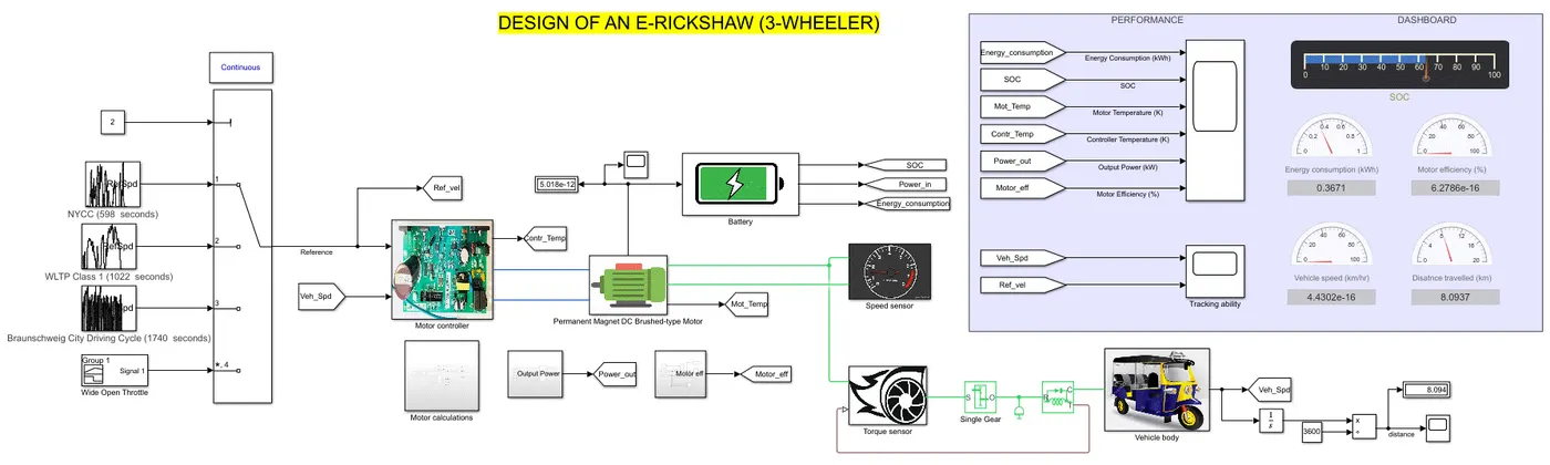
- The H-bridge motor controller is a power converter that receives supply from a PWM voltage block. It controls the power according to the vehicle performance requirements and transmits it to the motor (as can be seen by the positive and negative PWM terminals)
- The PID Controller (a PI is used in this case) is what ensures optimal performance. It minimizes the error between the reference drive cycle and the vehicle speed. If reference speed > vehicle speed, the accelerator signal is given in terms of a duty cycle ratio (between 0 and 1) which essentially translates to pressing the throttle harder. The Controlled PWM Voltage and H-bridge blocks converts that duty cycle signal into an appropriate PWM voltage signal to supply to the motor.
- If vehicle speed > reference speed, the deceleration signal is given, which translates to pressing the brake harder. The H-bridge controller is a power converter with regenerative braking, which means that it takes current back from the motor (which is acting like a generator) during braking, controls it appropriately as to not destroy the battery with a sudden insurge of current, and transfers it to the battery to charge it.
- A PID controller is vital because minimizing the error means taking into account factors like rise time, settling time, overshoot, and steady state error. Finding the best balance between these factors is what allows for the most optimized vehicle performance, such as lower peak power, lesser energy consumption from battery, reduced fluctuations in current, to name a few. The PID controller needs to be tuned manually in bigger models such as this one.
SENSORS:
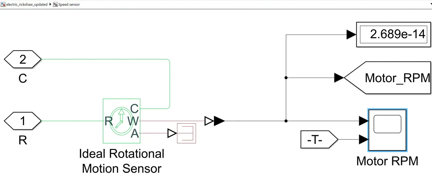
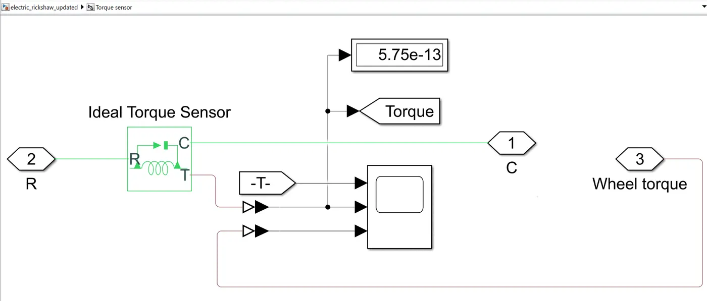
- Speed and Torque sensors are attached to the DC motor to compare the actual performance of the motor with the theoretical estimation (refer to Tractive Forces and Equations section above)
Motor speed (RPM):
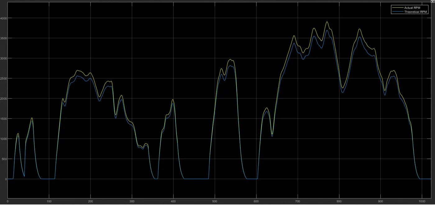
- Taking one of the reference drive cycles as an example, it is evident that the difference between the estimated motor RPM and actual RPM is very little, and the curves are identical in nature. This shows that the model is running correctly.
Torque:
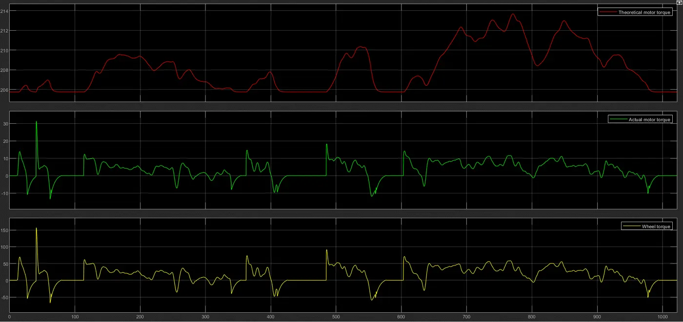
- Equations estimate that more than 200Nm of torque will be needed from the motor to run the vehicle. However, the motor only produces a peak of 30Nm, which is then multiplied by the gear ratio to give 5 times the torque to the wheels. The vehicle runs perfectly with 30Nm of motor torque, which shows that in this case the theoretical estimation is 6-7x of what's needed in actuality.
RESULTS:
DRIVE CYCLE #1: NYCC (598 seconds)
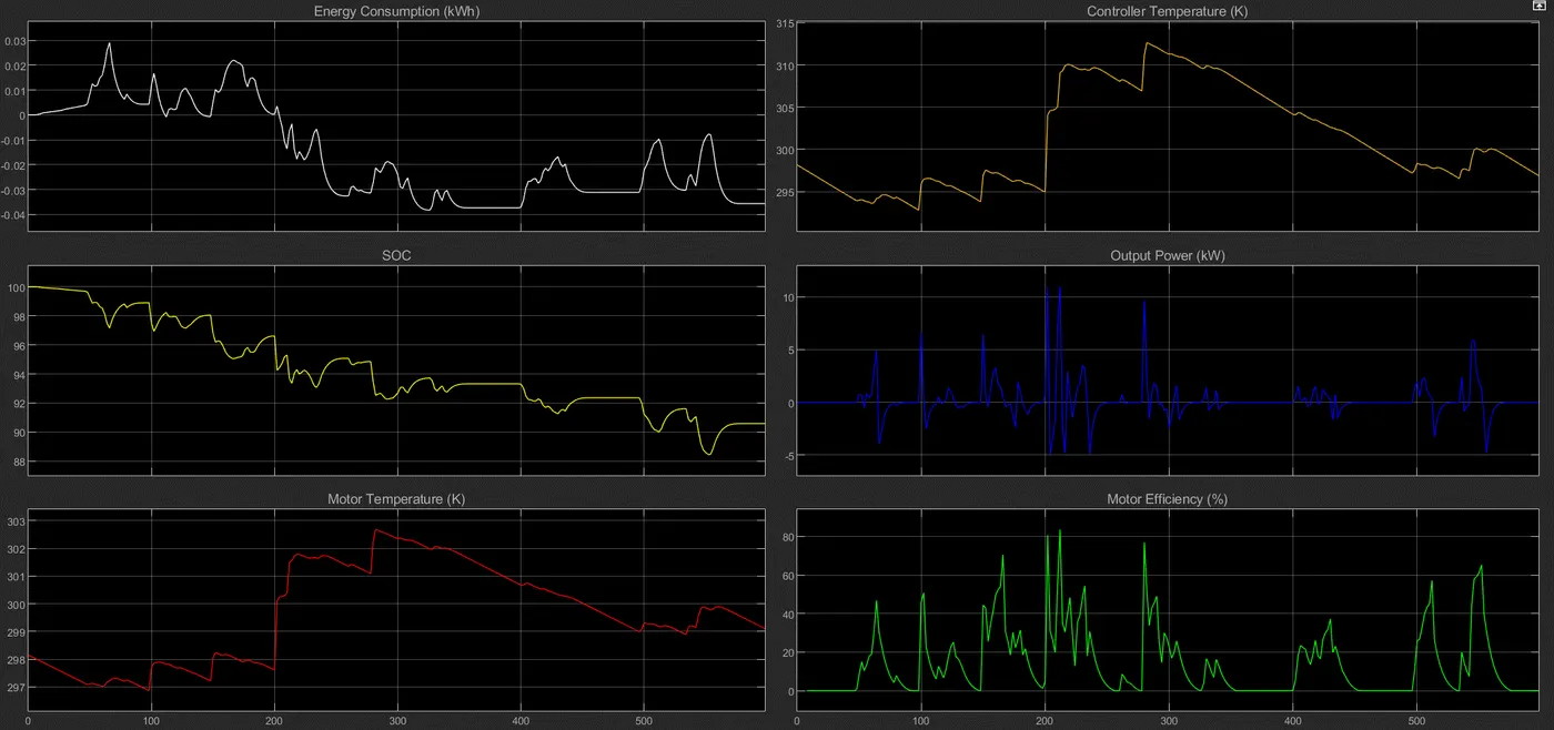
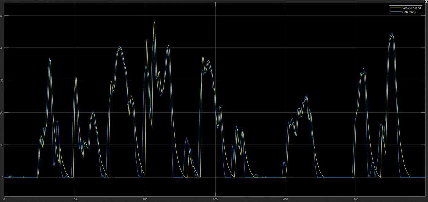
- Even with custom PI/PID tuning, the vehicle is unable to track this drive cycle with good accuracy. It is quite messy, as evident. This seems to be a very difficult reference cycle to follow because of the number of times the vehicle needs to accelerate and brake. The time period between those commands is also very short, making it highly difficult to follow precisely.
- Peak power requirement is about 11kW, which would be lesser if the drive cycle was tracked more accurately (for example, the spikes at 200, 220, and 280 seconds are the reason for that 11kW peak power; refer to output power at those respective time frames).
- Motor and controller temperature are under control. The reason being that thermal mass was set to 20,000 J/K - the higher this value, the more energy it would take to raise the temperature by 1 unit, and convective area was also added for both to dissipate heat. Without these two configurations, the controller temperature was excessive and touching 350K. One of the reasons for such an increase should be because of the number of times the controller has to step up and step down voltage to meet drive cycle requirements. Everytime voltage is stepped down or stepped up, a different PWM signal with a different duty cycle needs to be generated, creating more heat in the components and wires. Running on this kind of drive cycle without a proper thermal management system would not be recommended.
- Negative energy consumption means more energy is flowing back from the motor (which acts like a generator too) to charge the battery than is leaving the battery. Obviously not all of the energy recovered during regenerative braking can be used to charge the battery. Charge voltage/current also differs from discharge voltage/current, which is why the SOC isn't at 100% despite more energy coming in than going out.
- SOC and Energy Consumption graphs are not at their optimal values here, since the vehicle was unsuccessful in accurately tracking the drive cycle, and hence consuming more energy to try to meet the demand. If the vehicle tracked the reference well, energy consumption would be even more negative and SOC would be closer to 100%.
- Motor efficiency seems to fall mostly between 40-80%
DRIVE CYCLE #2: WLTP CLASS 1 (1022 seconds)
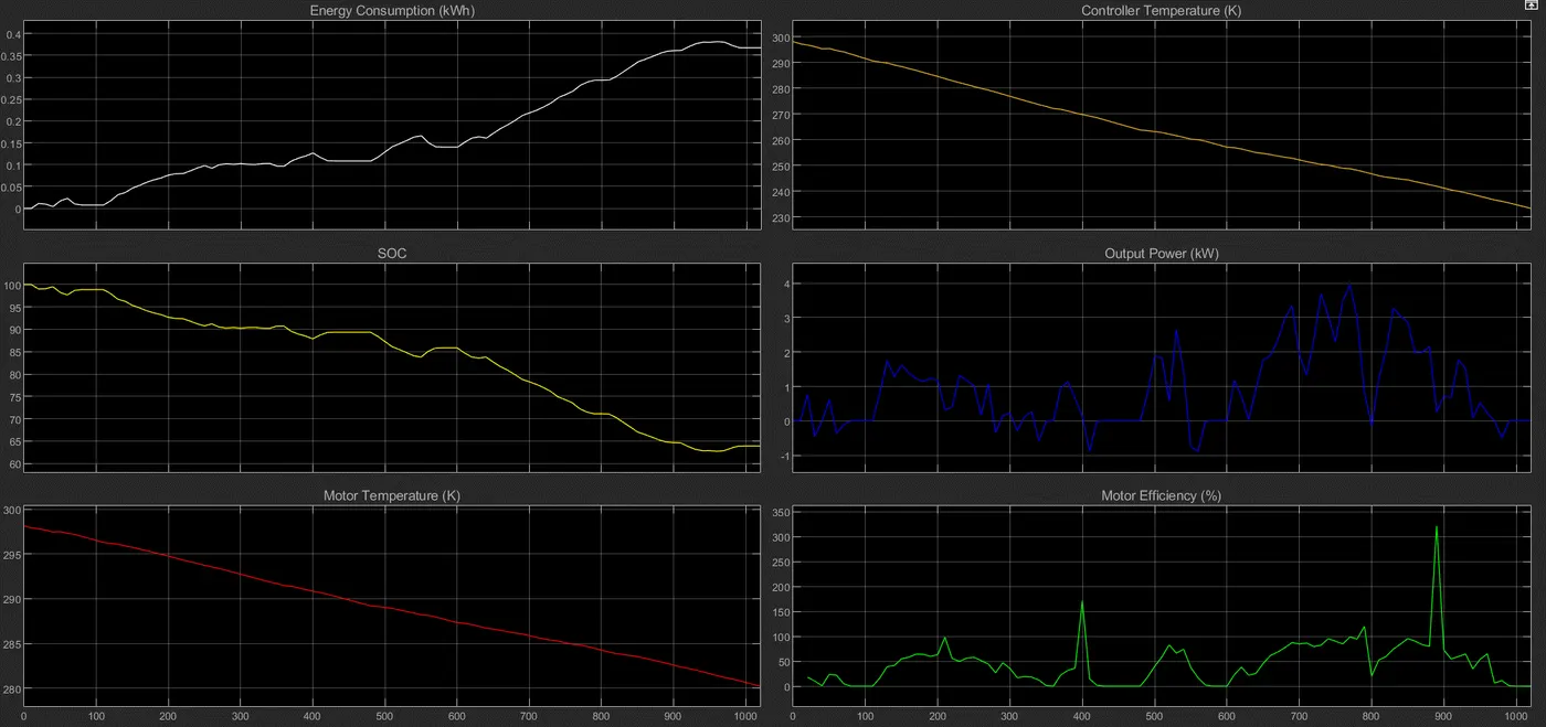
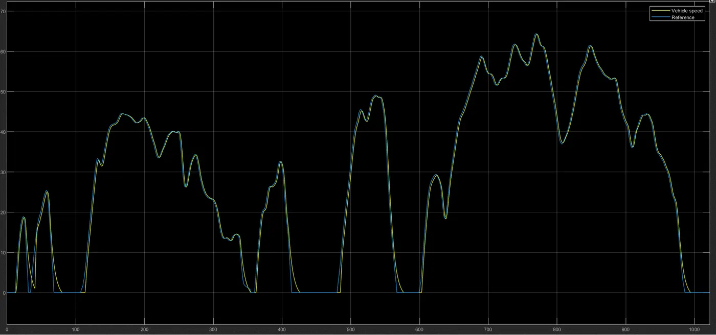
- Vehicle tracks reference with good accuracy, and due to this, other performance parameters such as energy consumption and SOC are close to their optimal values.
- Peak power requirement is about 4kW
- Due to thermal mass of 20,000J/K and convective heat transfer in place, and for this kind of drive cycle, motor and controller temperatures are cooling down from room temperature when they typically should be increasing. The type of drive cycle makes a huge difference to the temperatures of motor and controller.
- Effects of regenerative braking are clearly seen in SOC and Energy Consumption graphs as the battery keeps getting charged
- Apart from the two spikes, motor efficiency mostly falls between 50-95%. This number could be a lot more precise and more importantly consistent at a high value (80%+) if current had fewer fluctuations.
DRIVE CYCLE #3: BRAUNSCHWEIG CITY (1740 seconds)
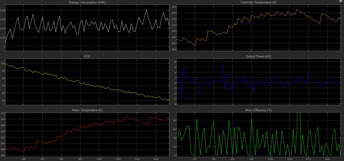
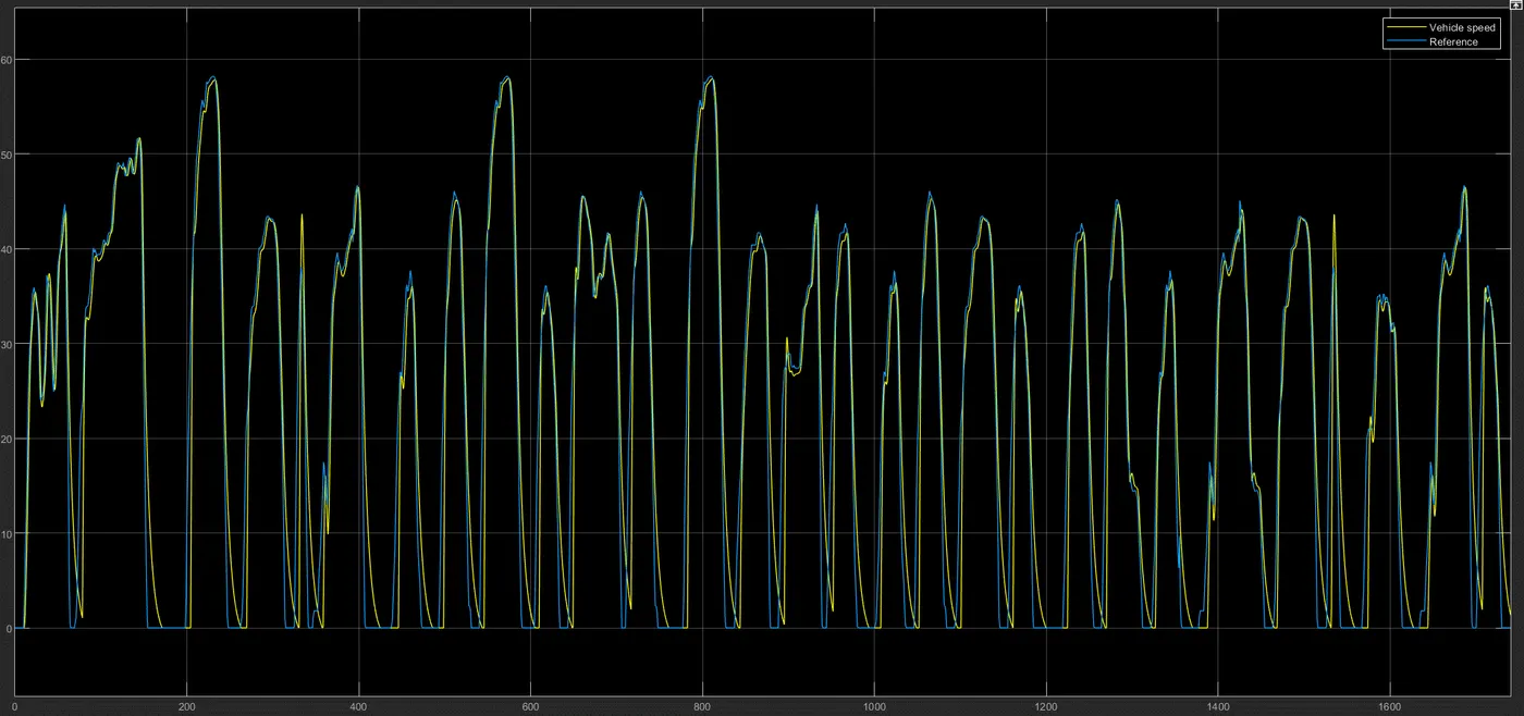
- Vehicle tracks reference fairly accurately
- Peak power requirement is about 7.5kW
- Motor and controller temperature are still under control despite this being the largest drive cycle, but controller temperature hit a peak of 323K, which indicates that a better thermal management technique needs to be in place.
- Motor efficiency is mostly falling in between 50-80%, barring that one spike at 1300sec
DRIVE CYCLE #4: WIDE OPEN THROTTLE; 45KMPH FOR A DISTANCE OF 100KM (8250 seconds)
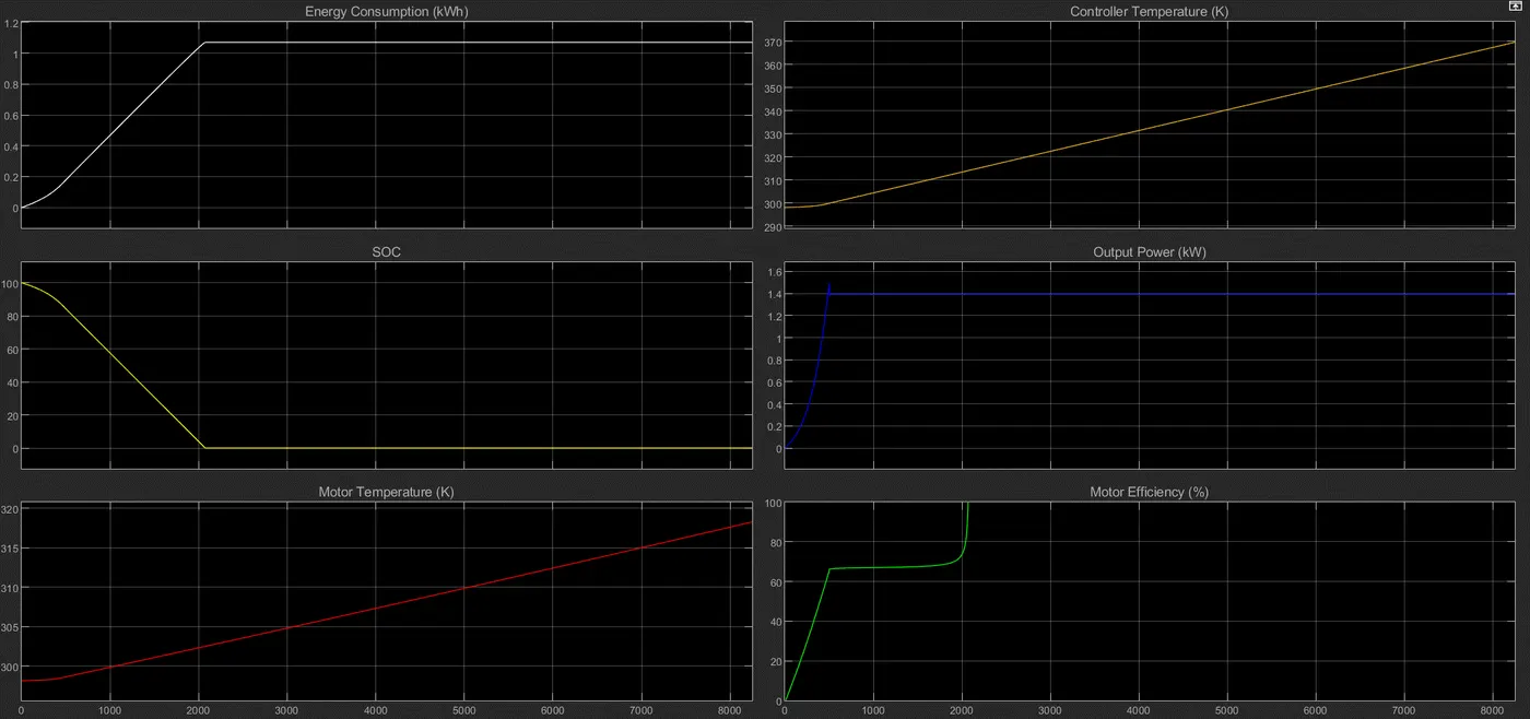
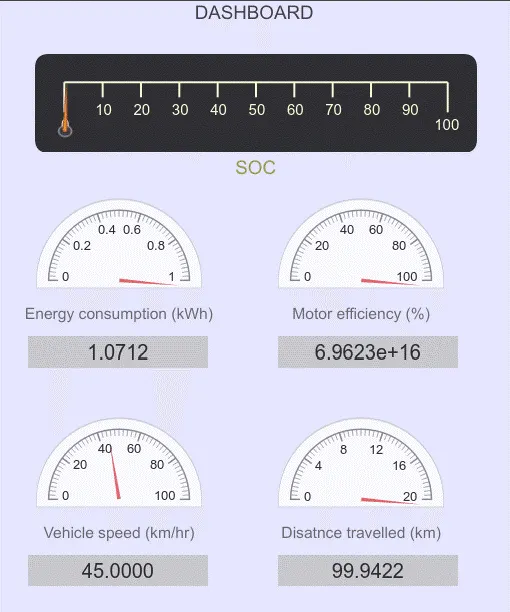
- WOT at 45kmph for a distance of 100km is clearly not sustainable unless multiple parameters such as battery capacity, vehicle weight, gear ratio are changed. SOC depletes to 0% at about 2000sec, and controller temperature goes beyond limits such that it will burn out if it has to run the vehicle at a constant speed of 45kmph for 100km.
- This model is not built to test a WOT scenario such as this one.