Creating Conceptual mass in REVIT and Creation of Sinusoidal curve and a Parametric stadium using Dynamo
1) Using Dynamo create a set of sinusoidal points and create a curve and create a surface out of the curve.
Aim:To create a set of sinusoidal points, create a curve and To create a surface out of the curve.
Procedure:
Step 1:
Open the Revit software, Select architectural template and click on the dynamo option in the manage toolbar.
After opening the dynamo, double click on the dynamo screen.
Step 2:
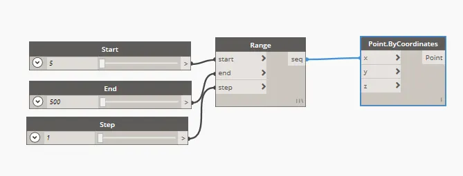
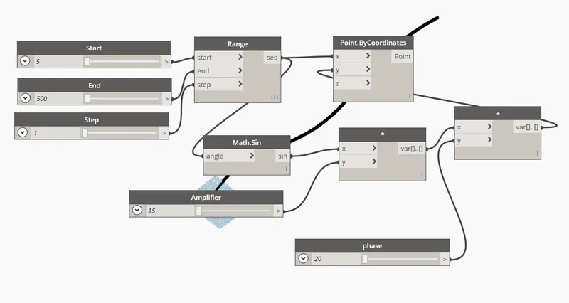
In the library search integer slider and create 3 sliders rename them as Start,End,Step.Give the values.
In the library search range and connect all three sliders to the range appropriately.
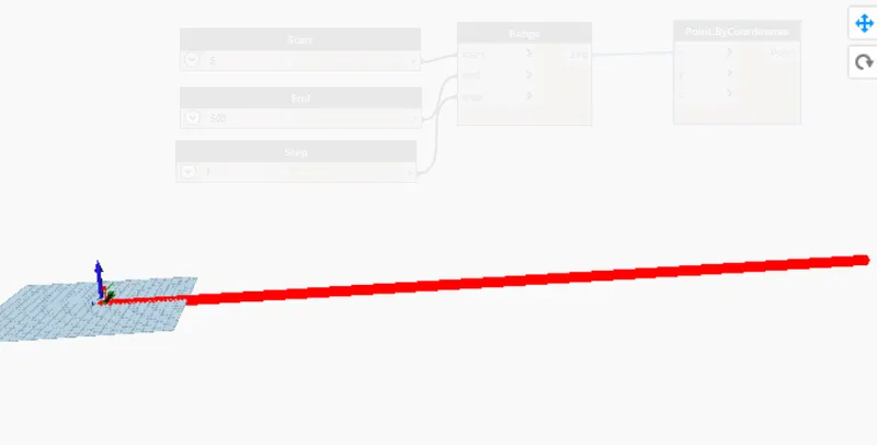
In the library search Point by co-ordinates click on it connect range to the X-co-ordinates.
Step 3:
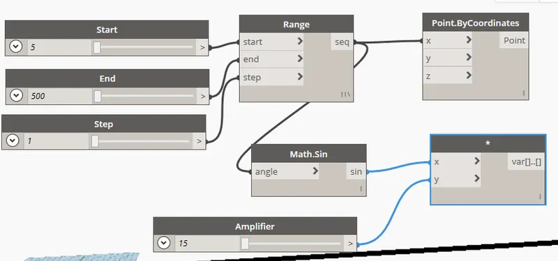
In the library search sine curve by the command math.sine.Connect the X-cordinates to the sine curve.
Create another slider and name it as amplifier and give the value.
Create product function by using product and connect the sine and amplifer to the product function.
Step 4:
Create addition function by using add and Create another slider and name it as phase and give the values.
Join the product and phase to the add .
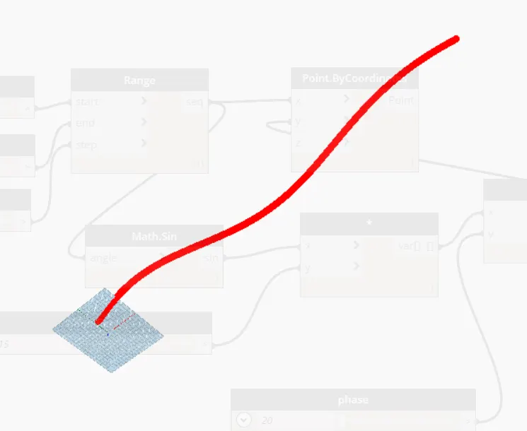
Connect from add to Y- coordinate.
Step5:
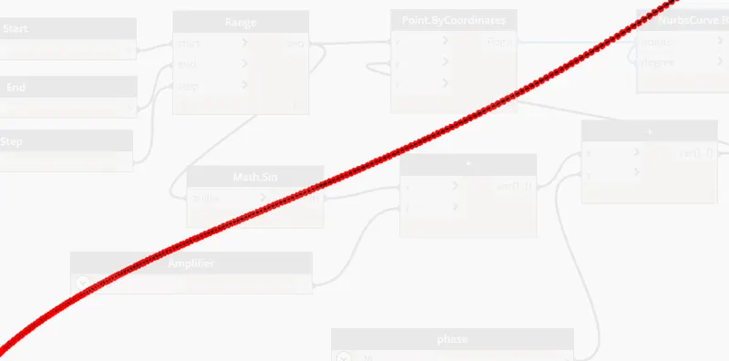
Create curve by using nurbscurve and also create a slider for the degree and give the value as 2 or 3.
Connect co-ordinate points to the nurbscurve and degree.A line is formed by connecting all the lines.
Step 6:
Select all the input based functions and amke it as group.To make it as group goto edit slect'create node from selection.
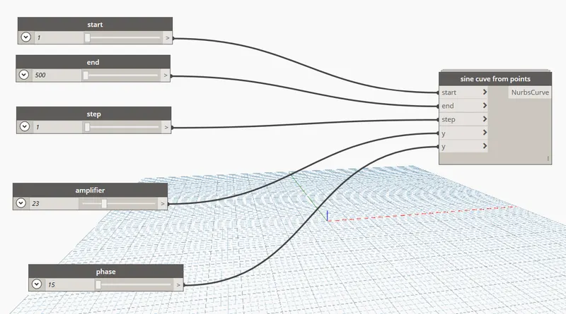
After creating group copy and paste it two times and adjust the phase value.
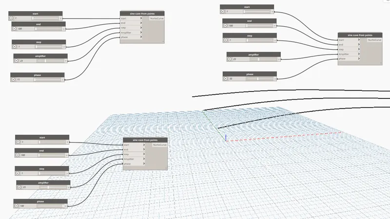
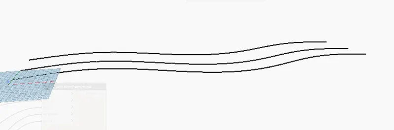
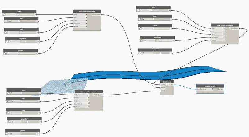
In the library search list.create and surface by loft .
Connect all sine cuves to the list .crete and to the list to surface by loft .
Result:
Created a set of sinusoidal points.
Created a sinusoidal curve.
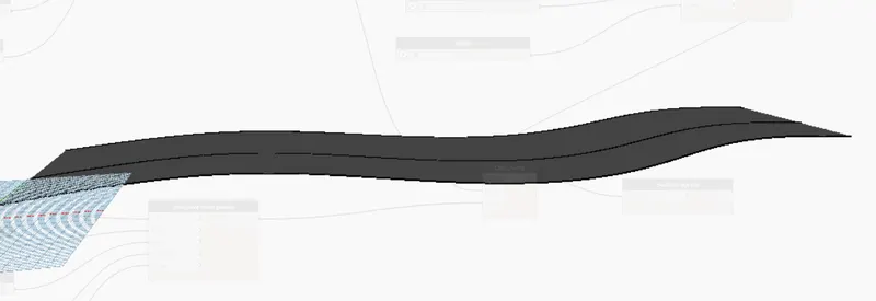
Created a surface out of the curve.
2) Create a conceptual layout of floor plan in dynamo. Using the tools available in dynamo link the lines to appropriate model elements in revit by choosing the wall types and wall parameters. Make use of the sliders to slide through the height of the wall and length of the wall.
Aim:To create a conceptual layout of floor plan in dynamo using the tools available in dynamo link.
Procedure:
Step 1:
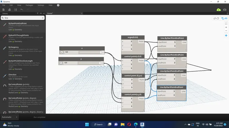
Create two integer sliders and name them as x and y, and give the minimum integer value as 100.
In the library search point by coordinates make 4 copies of it.Connect created integer sliders to the point by coordinates.
Step 2:
In the library search line by start point andend point make 4 copies of it.
Connect point by coordinates to the line.
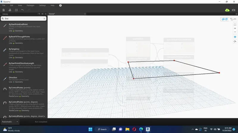
Then the rectangle is created by coordinate points.
Step 3:
Creation of walls:
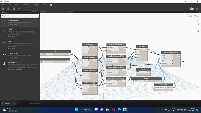
In the library search list create,wall types,levels ,wall by curve and height,integer slider and place all them into the work space.
Rename the slider as height and give the height as 10'.
Select the type of the wall as generic -12" wall.
connect all of the apporpriately shown in figure.
Step 4:
Creation of floor:
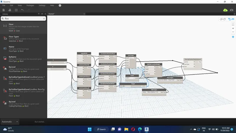
In the library search floor types,floor by outline type and level and place all them into the work space.
Select the type of the floor as generic -6" floor.
connect all of the apporpriately shown in figure.
3) Create an array of model elements in Revit. Use dynamo to vary the properties of model elements by using the slider or code block.
Aim:To create an array of model elements in Revit using dynamo to vary the properties of model elements by using the slider or code block.
Procedure:
Step 1:
Open the Revit software using the architectural template.
Create columns of 18X24" .
Step 2:
Open the dynamo tool, and then the dynamo will be opened.
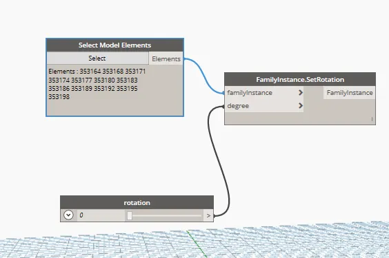
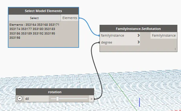
In the library select model elements, integer slider and family instance.
Reaname the slider and give the value for the rotation.
Connect elements of select model elements to the family instance of family instance.
Connect integer slider to the degree of family instance.
Result:
Created an array of model elements in revit using dynamo to vary the properties of model elements by using the slider or code block.
4) Create a conceptual mass in Revit and develop a parametric column by dividing the surfaces and apply the concepts similar to used in parametric walkway modelling. Use triangular bent or square shaped panels to add finish to the parametric column.
Aim: To create a conceptual mass in revit and develop a parametric column by dividing the surfaces and,To apply the concepts similar to used in parametric walkway modelling.
Procedure:
Step 1:
Open the Revit software, and select the new option in the family.
Select the mass in the conceptual mass folder.
Using the spline tool to draw the walkway curve.

Now, using spline tool draw the desired outline for the walkway.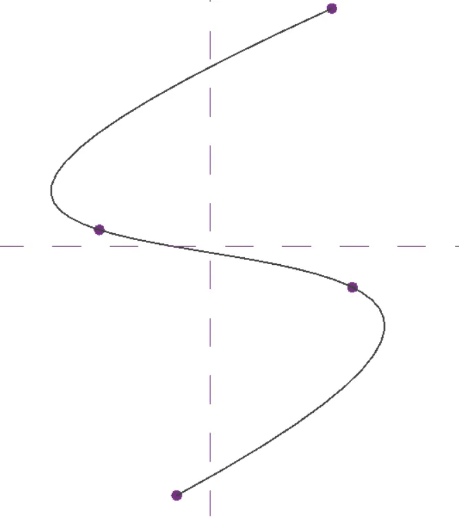
Now, we have to create a profile to sweep through the curve.
For this, we have to set the workplane at the points and develop a polygon at the workplane keeping the point as centre.
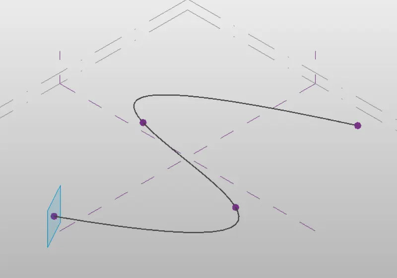
Now, a polygon is developed with point as center.
Similarly, workplane and polygon is developed at all the nodes.
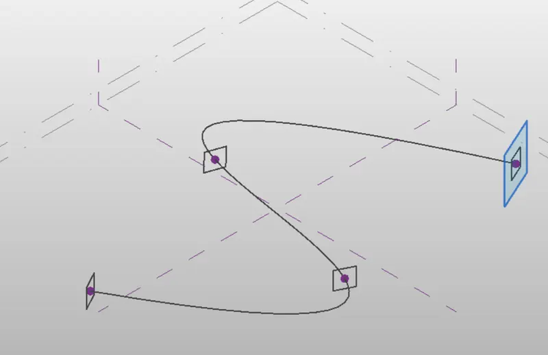
Now, we have to create the surface which done through sweep.
For this, select all the polygons and the curve line and choose create form option.
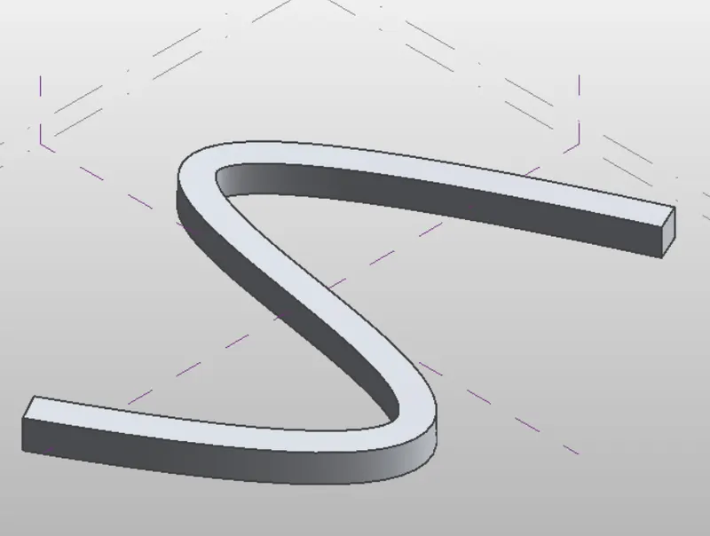
Now, select the entire form and then filter and retain only the form.
Now, select the form --> divide surface --> Then provide the pattern (triangle bent).
Now, open a new family -->Curtain panel pattern based.
Now, select the pattern as triangle bent.
Then, create a reference point at centre of the face.
Then draw a circle of radius 3" at that reference point.
Now, select the pattern, refrence plane and circle created and choose create form.
Now, load this into the project.
Now, select the enitre form of the walkway and filter it to retain only the divided surface.
Then in the pattern select the family that we havee created just now.
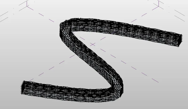
Hence, the conceptual mass have been created.
Result :
The conceptual mass have been created in Revit and is given as follows:
5.Use Dynamo to work on developing a Parametric Stadium. List your parameters and use the visual programming approach to complete the modelling, You can use the concepts discussed in parametric high rise tower in class for reference.
Aim:
To develop a Parametric Stadium using dynamo in Revit.
Procedure:
Initially open a new architectural template in Revit and then open dynamo.
Basic parameters to design a high rise structure is created as input in dynamo.
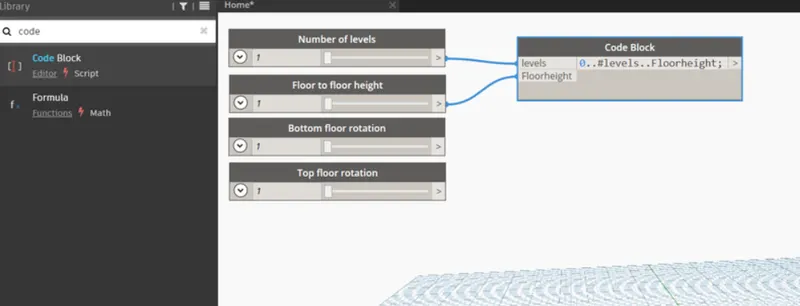
Four integer sliders is taken from the library for the following:
Number of levels
Floor to floor height
Bottom floor rotation
Top floor rotation
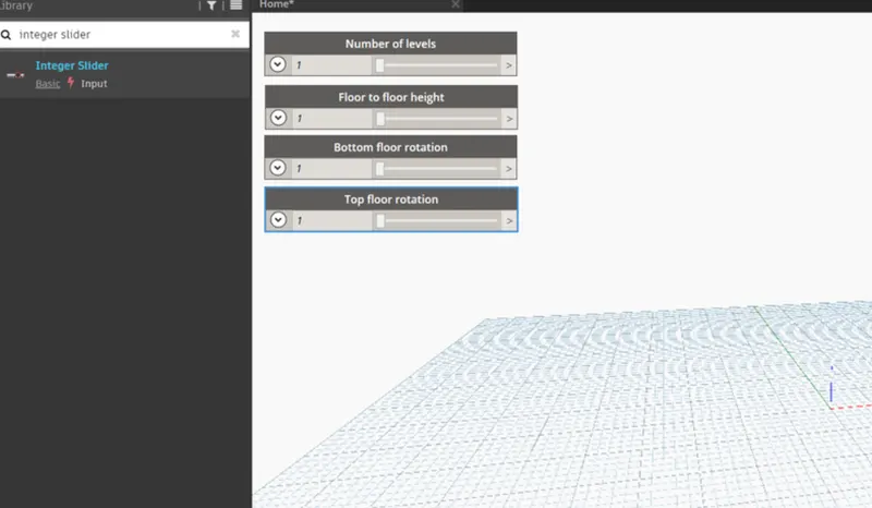
Now, insert a code block from the library to combine level and floor to floor height and type 0..#levels..Floorheight.
Now, connect the integer sliders named as levels and floor to floor hegiht as input to the code block.
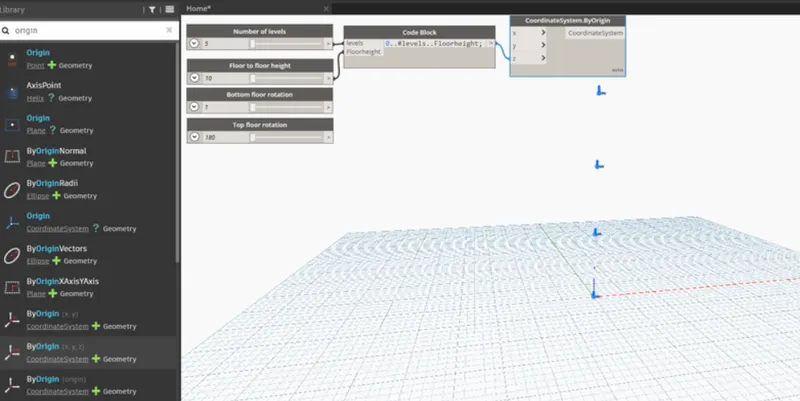
Now, search coordinates by origin in the library and insert it.
Then connect the code block as input for z coordinate in the coordinate by origin block.
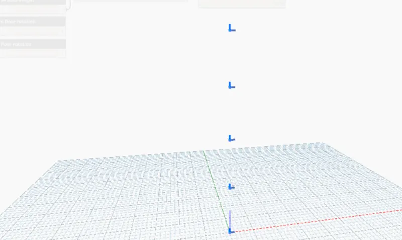
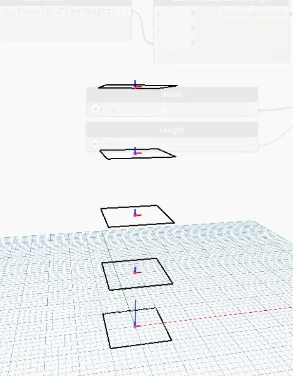
Five points are generated corresponding to 5 levels.
Now, insert rectangle by width and length from the library.
For this, inputs requied are coordinate system, length and width.
So insert integer slider for length and width.
Then connect the inputs for the rectangle block.
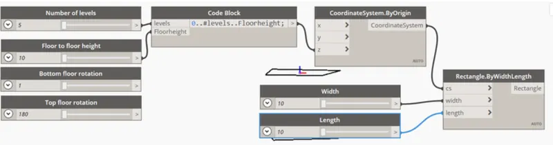
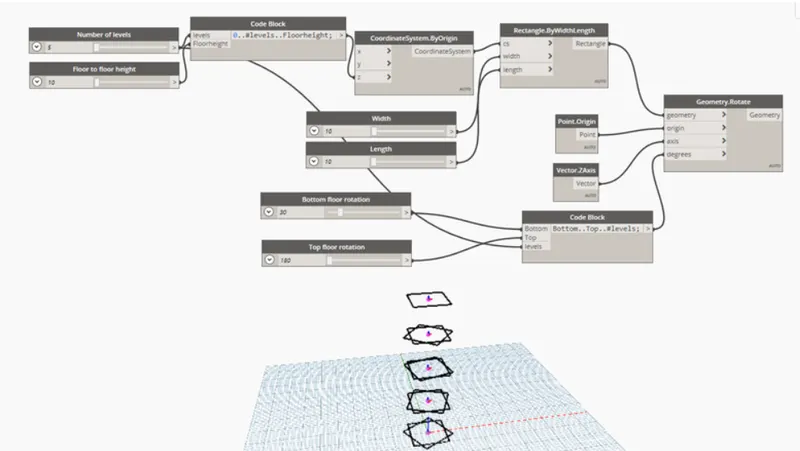
Now we have to rotate the geometry.
So, for this insert the rotate block from the library. The inputs required are:
Geometry : Rectangle block
Origin: insert an origin block from the library.
Axis: insert vector Z axis from the library.
Degrees: For this insert a code block and type Bottom..Top..#level. The inputs for this code block is already available i.e, Bottom floor rotation, top floor rotation and levels.
Now, we have to create surface, for this type surface by loft in library.
Then connect Geometry.rotate block as input for Surface by loft.
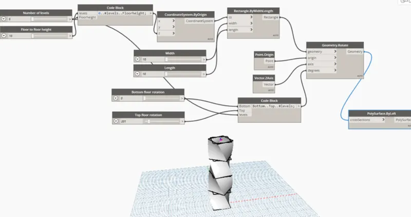
Hence, the parametric stadium have been created.
The number of levels and width and length of the rectangle can varied accordingly.
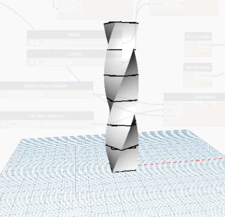
In revit structure is visible as follows: