Creating 3D Isometric view of various structural elements in AutoCAD
AIM;
1. Create a 3D Isometric View of the building with plan and elevation given.
2. Create the 3D View of the Building Façade as given in the plan and elevation.
3. Create the ismoteric 3d view of a stair with railing as shown in the plan and elevation.
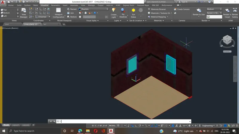
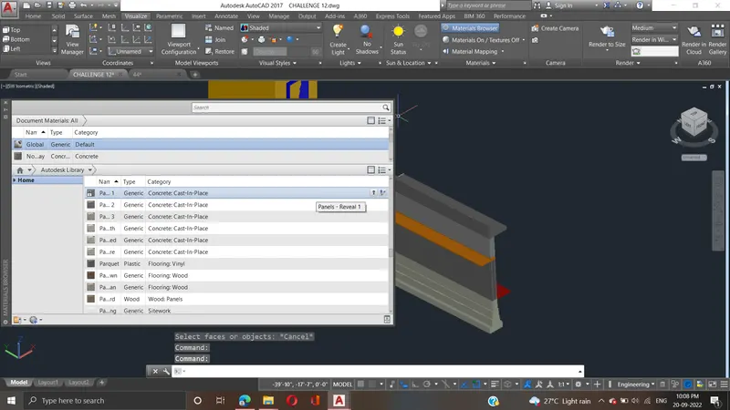
4. Create the 3D view of a Wall with spread footing . Create the Door opening only. Assume the size of the parpaet and the coping. See the plans and elevation for the details. Also, create a rendered view of the model with materials as of your choice.
PROCEDURE:
- Go to the top view
- In the command prompt type l to draw the lines of distance 10'-9" , 3',3-2" and thickness of 9"
- Now go to south west isometric view and
- In the command prompt type reg to region the object
- In the command prompt type extrude to extrude the object
- Go to right view and draft the rectangle using rec command
- Then go south west isometric view and extrude it to 9"
- Using sub command subtract the windows