Assignment 2-RADIOSS Engine File Editing & 3D Meshing Challenge
AIM:
- To study the starter file and Enginefile using RADIOSS profile
- Change the parameters according to the requirement in starter file and Enginefile.
- creating Tetra mesh on housing component Hexa mesh on Arm Bracket
OBJECTIVE
1. Check the material properties of the rail component and calculate the speed of sound in steel rail=_______
2. The length of the rail is about 1000 mm.calculate the time takes for a shock wave to travel from one end of the rail to the other.
3.Time for sound to travel length of rail=______
4.Edit the engine file so that the stress wave can be monitored, moving from one end of the rail to the other during impact -this will require a termination time equal to the time it takes for the sound to travel the length of the rail(set on/RUN card)
5.Set the frequency of animation output to a time that will give 20 animation steps(/ANIM/DT)
6.Change /print -10.
7.3d meshing tetra mesh and hex mesh
- Repeat class examples and, maintain the quality.
- Target tet size=5mm,hex size=10mm,tet collapse=0.15.
Procedure:
Import rad file in HYPERMESH.
open hypermesh select import
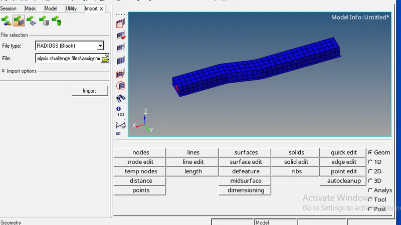
1.checking the material properties &calculating speed of the sound in mateial
goto Model<materials<steel
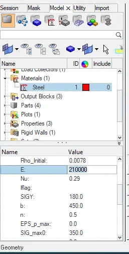
- we can check the material properties by opening rad000 file in notepad also
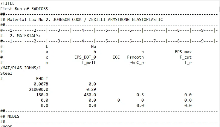
- Speed of the sound C=`sqrt(E/rho)`
`sqrt(210000/0.0078)`=5188.745 m/s.
shock wave travels with speed of the sound .shock wave speed=sound speed
=5188.745m/s
2.calculate time taken for shockwave to travel one end to other end.
Time= distance /speed
= 1000/5188.745
= 0.192725 ms
3. Calculate time for sound to travel in length of the rail = 0.192725 ms
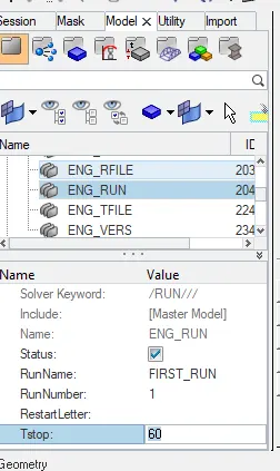
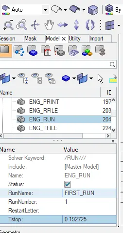
4.Edit the engine file so that the stress wave can be monitored, moving from one end of the rail to the other during impact -this will require a termination time equal to the time it takes for the sound to travel the length of the rail(set on/RUN card)
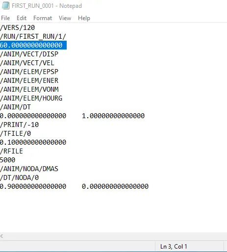
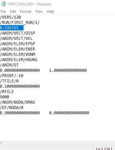
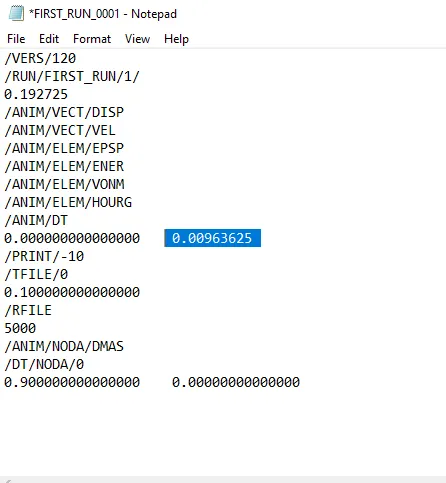
- In run card it is given 60ms so change it to 0.192725
- change it in FIRST_RUN_001
5.Set the frequency of animation output to a time that will give 20 animation steps(/ANIM/DT)
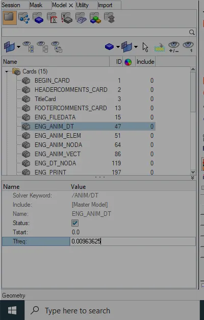
frequency= Time taken/no of animation steps
= 0.192725/20
=0.00963625.
- change this value in radioss file by selecting model check<Cards
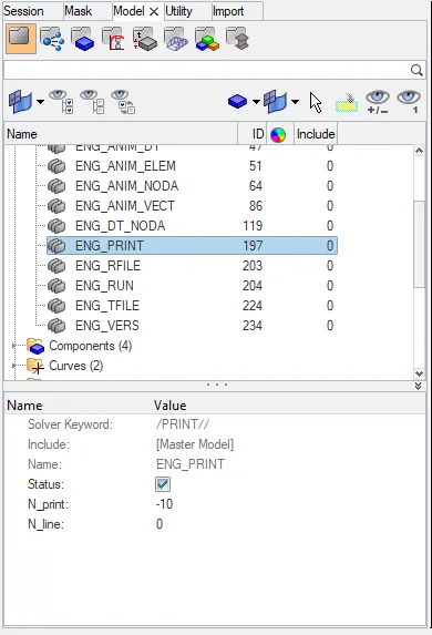
6.Change /print -10.
print value is changed by selecting model check<cards<ENG_PRINT
7.3d meshing tetra mesh and hex mesh.
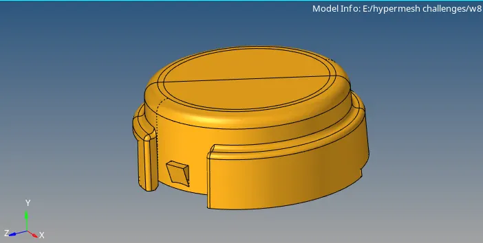
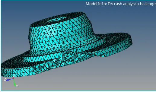
Housing component:
CAD model:Housing Model
Procedure:
- Imort the model by selecting import<model
- keep the graphics area in topomode then delete solids by selecting delete<solids<displayed<delete
- quality parameters should be given by selecting Tools
- then delete fillets which are having less then 2mm
- geometry cleanup should be done by geometry clean up tools.
- remove surfaces having less distance.
- for meshing Go to 2D<automesh<Target element length 4<trias<surfaces<select displayed.2D mesh will be generated.
- For quality check Goto Tool<check elements.adjust the failed elements till failed element become zero
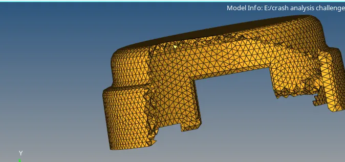
- Now we have to convert 2D mesh into 3d tetra mesh by selecting 3D<tetra mesh<select elements<displayed<then click on mesh
- now we have to check the quality of 3D mesh.Go to tool <check elements<3D<tet collapse we have to work on the model upto tet collapse become zero.
- same procedure have to be followed for model 2.
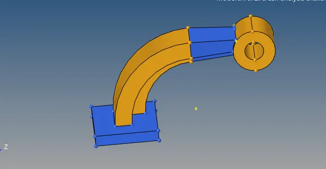
Hexa meshing of ARM BRACKET:
CAD file:
Procedure:
- Imort the model by selecting import<model
- keep the graphics area in topomode then delete solids by selecting delete<solids<displayed<delete
- hide all components except base.
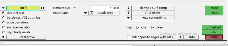
- mesh Top surfa ce with quad elements by 2D<automesh<surfaces<select top surface<element size 10<quads only<click on mesh
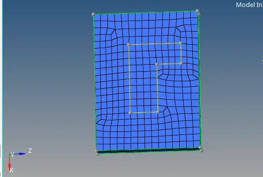
- Then go to 3D<element offset< select solid layers<element offset select elements<along geometry to follow(select two side faces)< No of layers will be 5<click on offset+
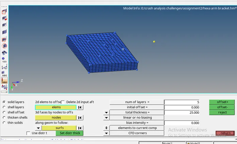
- Now hide 3D elements by selecting tool<mask<click on elements<by configure<hex8<displayed<mask.now we have only 2D elements
- For arm curve we use spin option for this.Go to 2d<spin<select 2d elements which we want to spin<we need a centre point go to distance<3node<drag mouse on the line select points randomly<select circle centre.
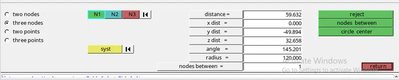
- give angle 90<on spin 25<select axis as x-axis<select base point<select spin-
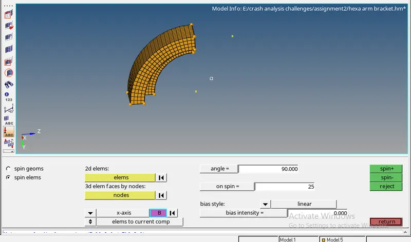
- go to tool<faces<components<select model 4<click on find faces.

- Hide all components Except arm straight go to we need destination elements for linear solid command<go to 2d<automesh<mesh<mesh elements should be same as source elements.
- go to 3D<linear solid<from elements <select elements<to elements<select elements<alignment<select 2nodes in from elements<alignment<select 3nodes in to elements<density=12<select solids
- go to tools<faces<delete faces

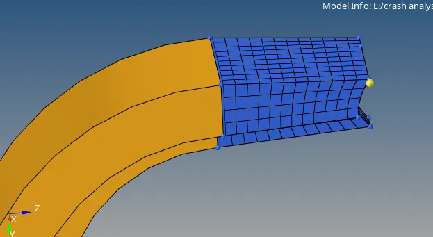
- for boss we need to mesh top surace 2d<automesh <select surfaces and adjust the mesh.
- then create a tempnode by projecting node on this line
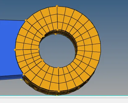
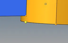
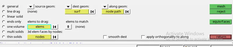
- Go to 3D<solid map<general<source geometry none <destination geometry select bottom surface<along geometry as nodepath<elements to drag select topsurface elements<click on mesh
- we need to delete 2D elements go to delete<elements<by configure<quad4<displayed<select entrities<delete

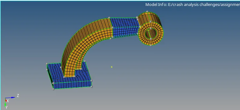
conclusions :
calculations are done successfully and edited them in the engine file.
tetra mesh and hexa mesh has done on the given models