Assignment 6-Frontal Crash Simulation Challenge
OBJECTIVE:
Frontal crash-BIW
- Check unit system and either follow[Mg mm s] or [Kg mm ms].
- Create appropriate interface ,friction 0.2 and recommended parameters.
- Make sure of no penetrations and intersection.
- Correct rigid bodies if any issues.
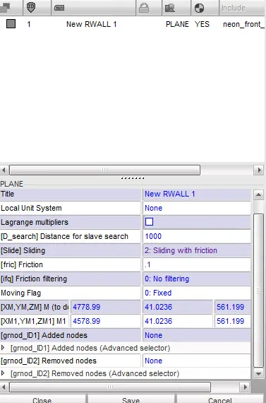
- Create rigid wall with friction 0.1.
- Compare the model weight with the full scale 300k nodes model and use added masses to reach target weight 700kg while getting CG about the required range.
- Initial velocity 35 mph.
- Use model checker to ensure good quality.
- Time-step :0.5 to 0.1 microseconds.
- Run 80 ms.
Output requests:
- Sectional force in the rails at location of indicated node 174247.
- Axial force received on the rails from bumper.
- Shotgun cross sectional forces.
- A pillar cross section.
- Acceleration curve received on the accelerometer at base of B pillar (on B pillar rocker).
- Intrusions on the dash wall 66695,66244.
1.Checking Unit system:
- open neon_front_0000.rad file in that it will show us which unit system is followed.

here it is following KG mm ms unit system.
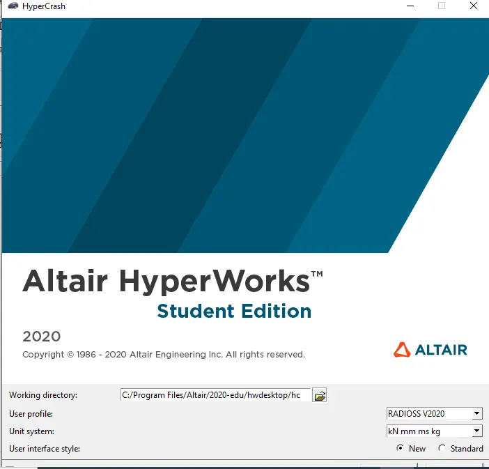
- while opening hypercrash it will ask which unit system to be followed according to above we will follow Kg mm ms KN .
2.Import neon_front_0000.rad File in Hyper mesh and hyper crash.
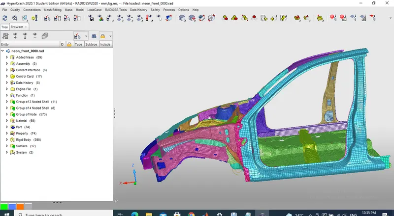
3.checking penetrations and intersections:
- in hyper crash Go to quality
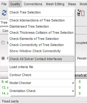
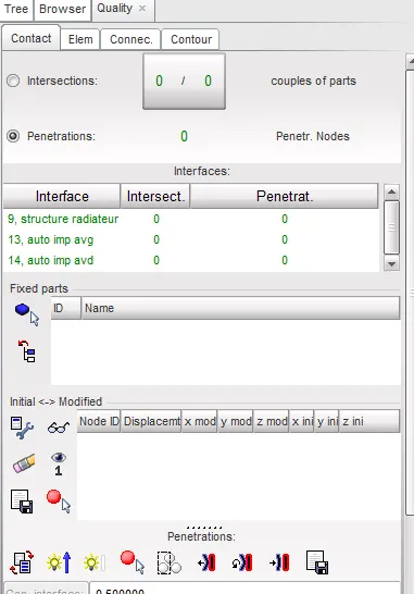
4.Compare the model weight with the full scale 300k nodes model and use added masses to reach target weight 700kg while getting CG about the required range:
- The centre of gravity of vehicle is all the components of masess are acting at one point.
- due to sunroof of the top the centre of gravity will shift upwards.due to battery pack on the bottom centre of gravity shift to downwards.
Added masses:
- Adding mass is essential in order to obtain centre of gravity at optimum position.
- checking of centre of gravity is done by open hyper crash
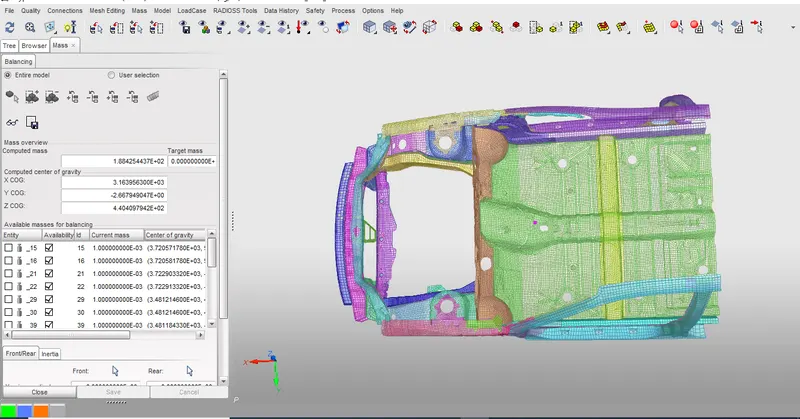
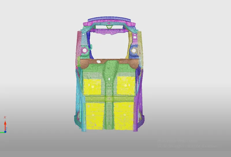
- Here the computed mass is 188.42kg but the required weight is 700kg with Appropriate position of COG.adding mass will be option to get the COG in appropriate possition.
- To add the mass go to load case
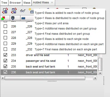
- the centre of gravity is shifted due to added mass.
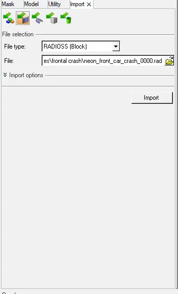
5.Export HyperCrash File in HyperMesh:
- After making changes in hyper crash file it will be save as by File
- then import the file in Hyper mesh by File
- then import the file in Hyper mesh by File
6.Contact Interface:
- In this case the type 7 contact interface is defined.Type7 interface is a multi usage impact interface,modelling contact between a master surface and a group of slave nodes.
All limitations that were encountered with interfaces TYPE3,TYPE4,PYPE5 are solved with TYPE7 interface.
- A node can at the same time be a slave and master node.
- Each slave node can impact each master segment except if it is connected to this segment.
- A node can impact more than one segment
- A node can impact on the two sides
- it is a fast search algorithm.
Limitations of Type7 interface are:
- Time step is reduced in case of high impact speed or contacts with a small gap.
- It does not work properly if used with a rigid body at high impact speed or a rigid body with a small gap
- It does not solve edge to edge contact (to solve this ,/INTER/TYPE11 should be used along with TYPE7)
Interface Type7:Node to Surface contact
- It is the node to surface contact and it is a universal type of contact.
- Gap is defined around the master segment and slave nodes and this gap can be variable and constant.
- The slave is kept out side of the master gap by resistive force application
Recomended TYPE 7 Options:
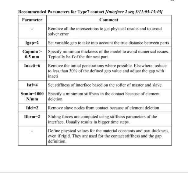
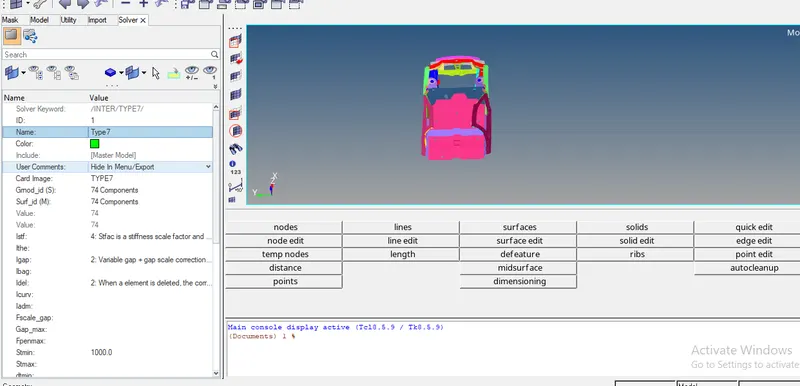
- Reviewing the selection of nodes of all components of vehicle model by inter
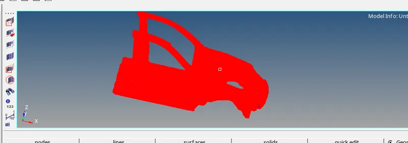
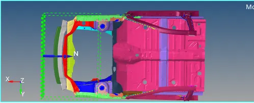
7.Rigid Wall:
- Rigid wall is created in hyper crash by go to load case
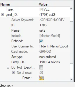
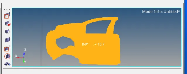
8.Intial velocity:
- Intial velocity applied by go to solver
- we can check by rightclick and review to see wether initial velocity applied or not.
9. Time-step :0.1 to 0.5 microseconds and Run time as 80ms :
- To assign the timestep go to model browser
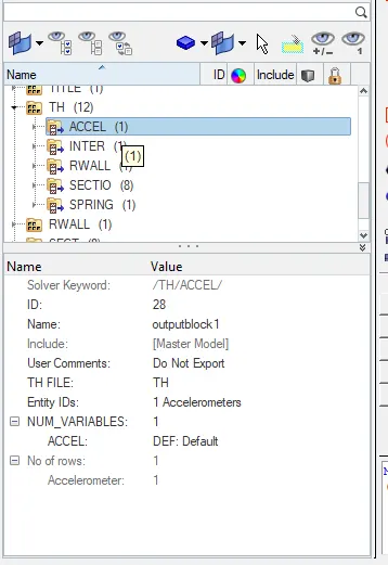
10.sectional forces :
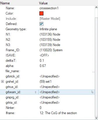
- The purpose of crash test of car against a rigid wall lies on the concept of sectional forces acting on the passenger inside the cabin.sections will be created different components of car i.e A-pillar,short gun,bumper,rails.
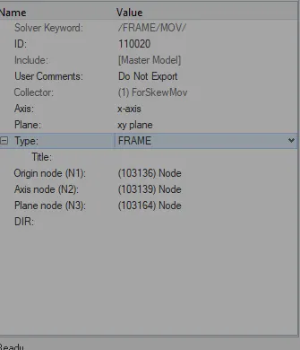
Frame creation :
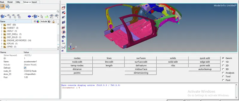
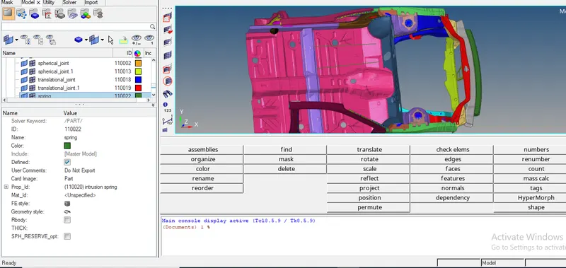
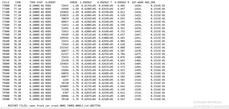
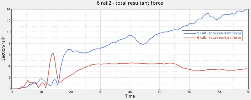
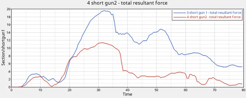
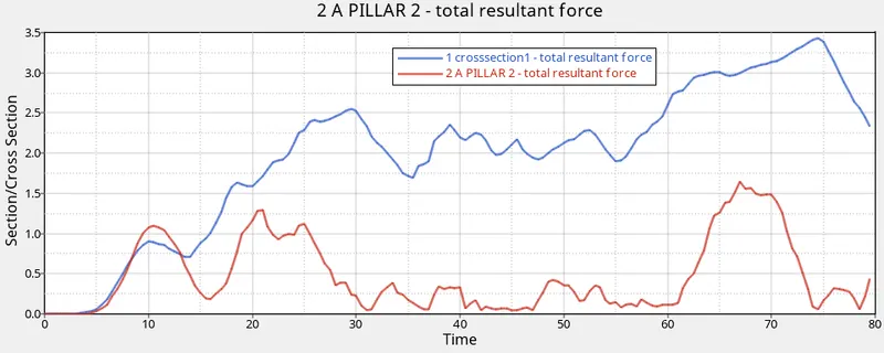
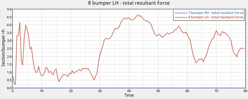
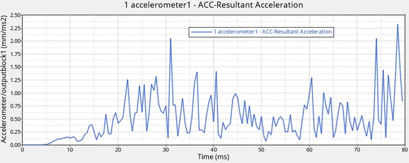
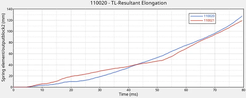
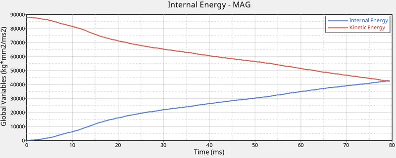
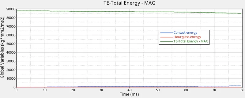
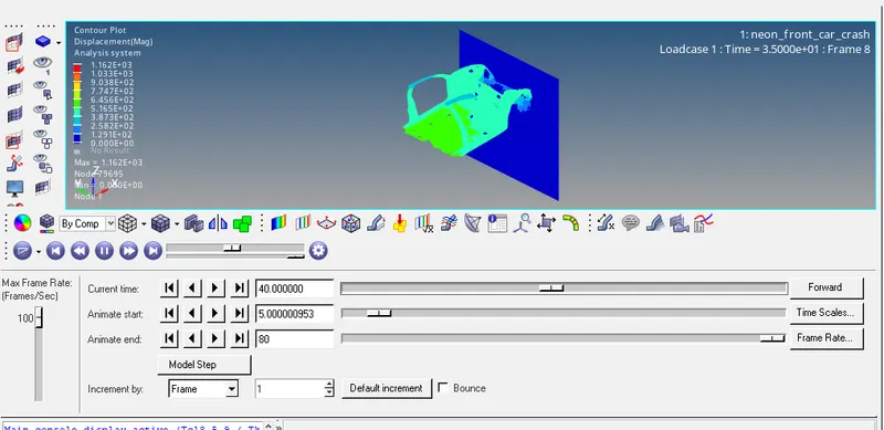
Go to solver browser Now go to solver browser< sect 11.ACCELEROMETER: 12.Spring elements for intrusions of dashboard : 12.Create TH cards: 13.Model checker : Go to tools after that we have to run simulation . check Energy error and mass error simulation: PLOTING GRAPHS: SECTIONAL FORCE IN THE RAIL COMPONENTS: Shot Gun: A PILLAR: maximum force in Apillar 1 is 3.5KN at 75ms and APillar 2 is1.7 KN at 68ms. Bumper: maximum force in bumper 4.7KN at 43ms . ACCELERATION CURVE: maximum acceleration 2.27 mm/ms^2 at 78ms intrussions : maximum deformation of spring at node 66695 is 130mm and at 66244 is 120mm I.E & K.E: Total Energy,contact energy,hour glass energy : displacement: conclussions: In this project when collission is take place a reactionforce will generate from the wall.which is called kinetic energy this energy hase huge impact .if this energy is taken by passenger he will injure siverly .in orderto overcome this the energy should be absorbed by the car component itself.from plot we can say that k.e is decreasing and I.E is increasing .from this we can say that kinetic energy is converted into internal energy thats why total energy is constant.hour glass energy is constant due to usage of recomended properties.