Assignment 5-RADIOSS Interfaces & Study of Effect of Notches Challenge
OBJECTIVE:
- Create the mesh for bumper assembly,mesh size should be 6mm.
- Run the crash tube model as it is.
- Change the Inacti=6 and run.
- Create the type 11 contact and run.
- Remove both notches and remove boundary condition on rigid body node then run.
- Create a new notch in the middle ,select the whole section and run.
- Create a new notch with nodes only from opposing 2 faces and run.
Note:
- Plot RWALL forces ,contact forces,internal energy and Create TH/PART for all parts and compare results for all cases.
- Comment your thought on why there is a change in the internal energies.
- How does the notch affect the results?
- Plot energies and note any difference.
Create the mesh for bumper assembly,mesh size should be 6mm:
- open hypermesh and import the model.
- clean the geometry
- goto automesh and element size is 6mm
- generate the mesh as component wise
- improve the mesh quality by removing trias and using quality tools.
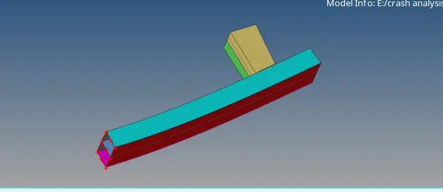
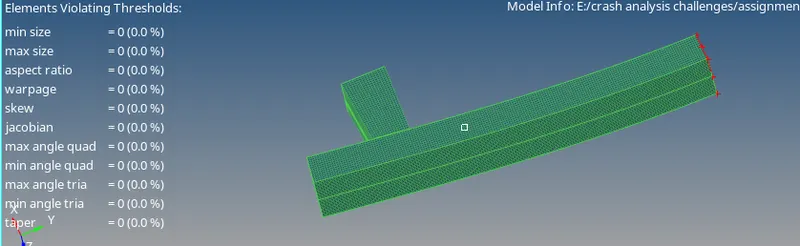
Case 1:Run The crash tube model as it is:
- open hypermesh
- import solver deck rad.0000 file.in this case the inacti is 0.Then run the simulation.
- in this animation first deformation will occur at the mid notch due to applied velocity
- after midlle the next deformation will occur at 2nd notch which is near the rigidwall.
- Here the notch elements deforming inside and the rest flat elements are coming outside.there is not required high forces where notch is there because of stress concentration.
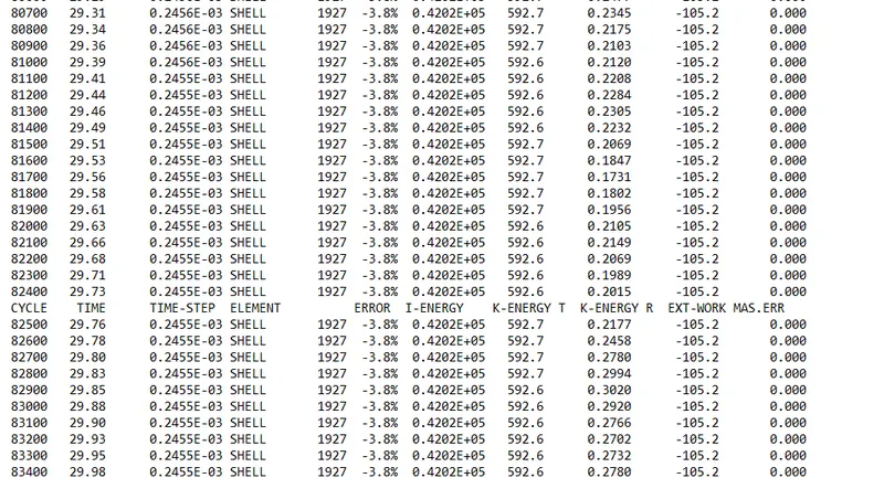
- As we can see the energy error is -3.8% it is acceptable.there is no mass error.
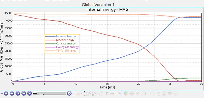
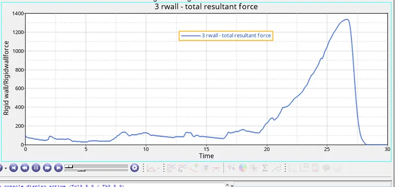
- Internal energy increasing because the tube continuous absorbs energy while crashing in to the rigid wall which results in deformation.after deformation completes the internal energy curve becomes constant.
- kinetic energy is high due to intial velocity.then its decreasing during deformation.after deformation slight increasing of kinetic energy due to rebounding.
- contact energy is atype of energy that is created when one element contacts with other element there is a opposite force create by element is called contact energy.there is no contact in the initial stage thatswhy in the graph contact energy curve is constant but during crushing a slight increase of contact energy due to buckling.while the entire tube press into the rigidwall the buckeled elements are forced into contact.
- Total energy slightly decreases due to increase of contact energy.
- Hourglass energy is constant due to using recomended properties.
CASE2:change the inacti=6 and run:
- In this case we will use hyper crash.
- import the crash tube.0000.rad file
- After importing we can go to a model browser
- Then export the file and open in hypermesh.then run the analysis.
- The inacti=6 is used to find out any initial penetrations are there.
- so the results are same as case1.
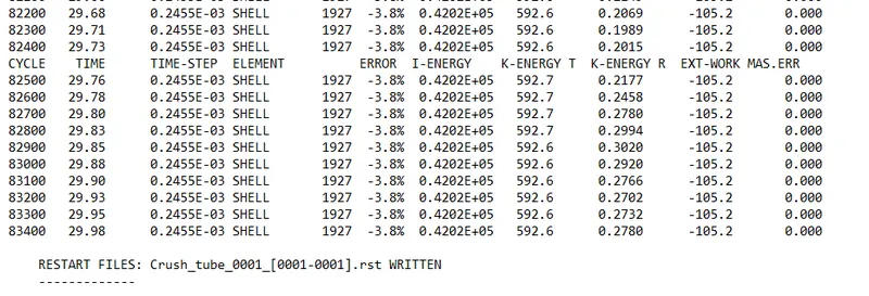
- The energy error is -3.8% and mass error is 0 .there is no difference in case 1 and case2
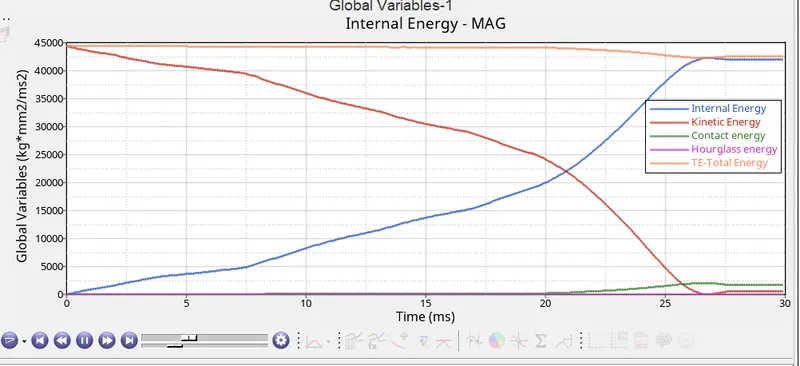
- the energy plot is sameas case 1 but if any intial penetration present the internal energy will start from non zero
Rigid wall forces:
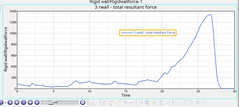
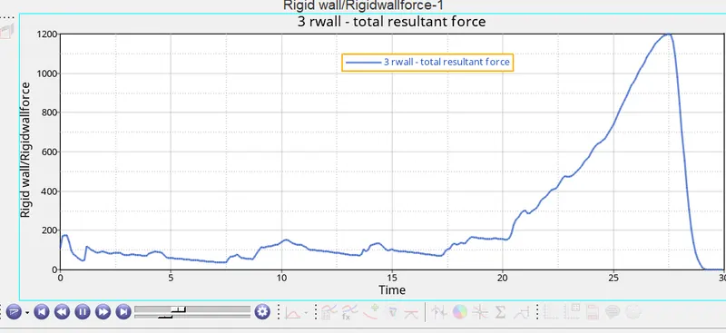
Rigidwall forces will increase where contact energy increases and after the deformation rigid wall forces will decrease.
CASE3:Create type 11 contact and run:
In this case create type 11 interface.then run the analysis
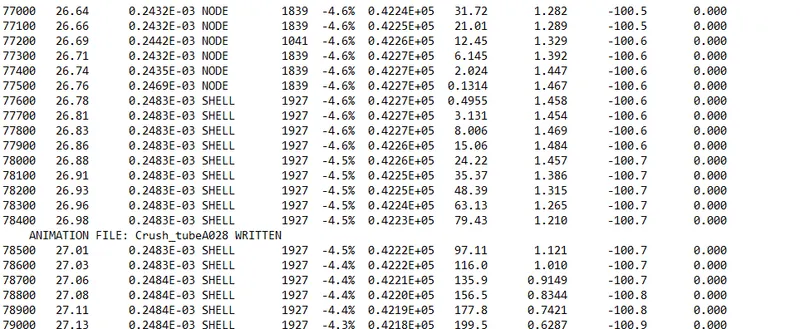
- Energy error is -4.6% and mass error is 0.
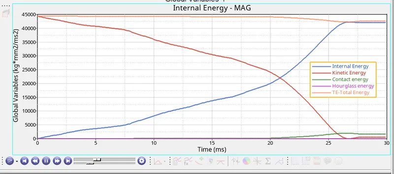
- Hour glass energy is zero due to QEPH formulation.
Rigidwall forces:
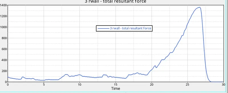
There is no much difference between this case and previous cases
CASE4:Remove both notches and remove boundary conditions on rigid body then run:
In this case we will remove notches by using align node option in hypermesh.then delete the boundry conditions and run the analysis.
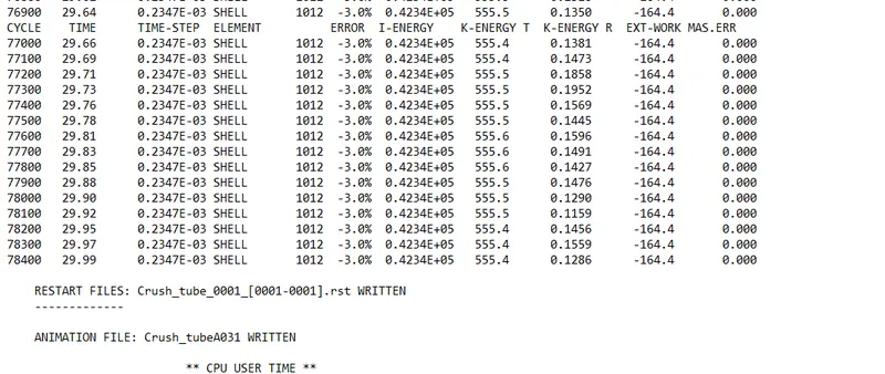
- In this case the energy error is -3.0% which is decreased compared to previous cases.mass error is 0
- There is no notch present in this model then the buckling starts at the contact of rigidwall and crash tube.
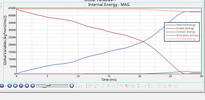
- compared to previous cases contact energy is slightly decrease due to abscence of notches.
Rigid wall forces:
CASE5:Create new notch in the middle and run:
- Using case4 file create notch in the middle by using translate command.
- as same as previous cases deformation will occur at notch first.then the region which is closer to the rigid wall deform next.
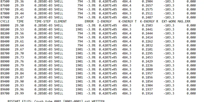
- energy error is -3.9% and mass error is 0.
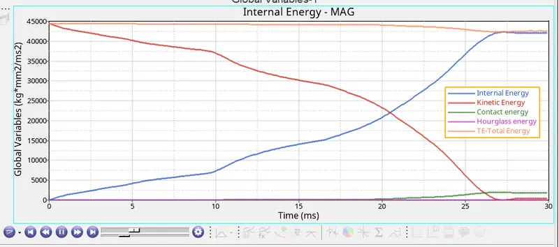
- The energy plots are same as previous cases.
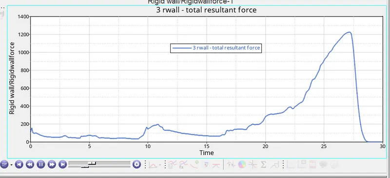
- There is no noticible difference between in case 4 and case5. in this case the contact energy incurred is morewhen compared to case1 and case2 .this is due to only one notch at the centre which increases the rate of deformation which inturn increases the rate of penetration
CASE6:Create a new with nodes only from opposing 2 faces and run:
- import case4 solver deck and create two notches on two opposing faces.run the analysis.
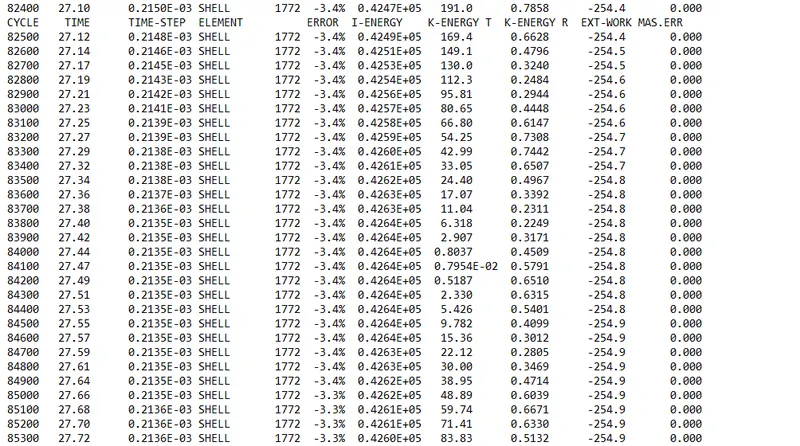
- the maximum energy error is -3.3% and the mass error is 0
- like the previous case buckling occurs at first in the region where the notch is present after that lower part of tube is deformed.finally the upper part deformedcompletely after some point.
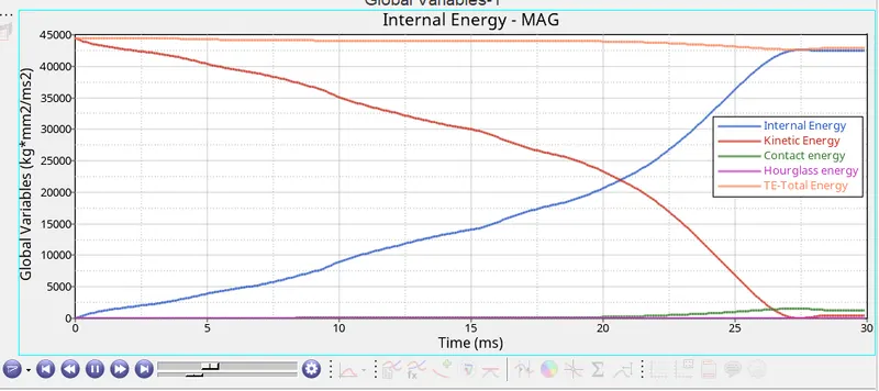
the energy graph is sme as previous cases.
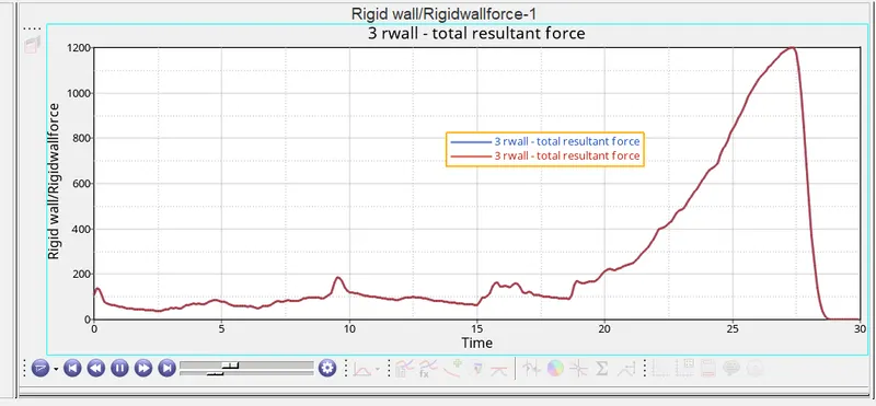
RESULTS:
| no of cycles | energy error | Internal energy | kinetic energy | contact energy | Rigidwall forces | |
| case1 | 83400 | -3.8 | 42000 | 45000 | 2500 | 1350 |
| case2 | 83400 | -3.8 | 42000 | 45000 | 2500 | 1350 |
| case3 | 90500 | -4.6 | 42500 | 45000 | 2500 | 1370 |
| case4 | 78400 | -3.0 | 42500 | 45000 | 2300 | 1200 |
| case5 | 89700 | -3.9 | 42000 | 45000 | 2500 | 1250 |
| case6 | 95900 | -3.3 | 42000 | 45000 | 2300 | 1200 |
Conclusions:
- From all the cases we can say that criteria "inacti" is required to be defined as it removes intial intersections in the model if they exist.
- it helps to obtain a more accurate result and also reduces the no of cycles&time taken to solve.
- type11 contact is given between two edges and requires lesser parameters to be defined and also takes comparatively lesser time to be solved than type7 contact.
- Notches are an important part of the model which helps in directing deformation when a load is applied.They help in making the component absorb maximum energy whwn a load is applied.