Courses by Software
Courses by Semester
Courses by Domain
Tool-focused Courses
Machine learning
POPULAR COURSES
Success Stories
AMERICAN CHOPPER
DESIGNING OF AMERICAN CHOPPER USING SOLIDWORKS OBJECTIVE:- This project involves design, assembly and rendering of american chopper model, a mototrbike with classical American roots which is custom made and innovative with spiderweb designed rim wheels and chromium themed fenders with its long front fork. The chopper…
Nikhil KUMAR
updated on 27 Apr 2020
DESIGNING OF AMERICAN CHOPPER USING SOLIDWORKS
OBJECTIVE:-
This project involves design, assembly and rendering of american chopper model, a mototrbike with classical American roots which is custom made and innovative with spiderweb designed rim wheels and chromium themed fenders with its long front fork. The chopper is built through featured based on solid modellling & surface modelling.
Parts used:-
- Transmission belt
- Kickstand
- Front fender
- Rear fender
- Oil tank
- Chain
- Pedal
- Front wheel
- Rear wheel
- Front fork
- Chassis
- Engine
- Gas tank
TRANSMISSION BELT:-
Transmission belt is used to transfer the power from engine to the rear wheel.
COMMANDS USED:-
- Sketch
- Offset
- Extrude
- Filllet

SKETCH
The Sketch is a 2D-dimensional representation of the model with the respect to plane/view.
OFFSET
This feature is used to create a one or more sketch entities, selected model edges, or model faces by a specified distance.
EXTRUDE
It is a feature to create a solid body using a sketch.
FILLET
It a feature used to creat rounded egdes.
KICKSTAND:-
Kickstand is used to support the chopper.
COMMANDS USED:-
- Sketch
- Loft
- Dome
- Extrude boss
- Extrude cut
- Split
- Fillet

SKETCH
The Sketch is a 2D-dimensional representation of the model with the respect to plane/view.
LOFT
It is a process tp create a solid body using two reference cross-sections.
DOME
The feature is used to create a round or elliptical countour to one or more planar or non-planar faces.
EXTRUDE
It is a feature to create a solid body using a sketch.
EXTRUDE-CUT
It is a feature to remove the unwanted material form solid body.
SPLIT
This feature is used to create multiple parts from an existing part.
FILLET
It a feature used to creat rounded egdes.
FRONT FENDER:-
Front fender is mounted above the front wheel and it is used to protect the front wheel from dirt.
COMMANDS USED:-
- Sketch
- Offset entities
- Trimm entities
- Revolve
- Split

SKETCH
The Sketch is a 2D-dimensional representation of the model with the respect to plane/view.
OFFSET
This feature is used to create a one or more sketch entities, selected model edges, or model faces by a specified distance.
TRIM ENTITIES
Trim entities is used to cut the line from the sketch to create the desired sketch.
REVOLVE
It is a process of creating a solid body based on a sketch and centre axis.
SPLIT
This feature is used to create multiple parts from an existing part.
REAR FENDER:-
Rear fender is mounted above the rear wheel and it is used to protect the rear wheel and it has customized paint job based on the chopper's theme.
COMMANDS USED:-
- Sketch
- Offset entities
- Trimm entities
- Revolve
- Split

SKETCH
The Sketch is a 2D-dimensional representation of the model with the respect to plane/view.
OFFSET
This feature is used to create a one or more sketch entities, selected model edges, or model faces by a specified distance.
TRIM ENTITIES
Trim entities is used to cut the line from the sketch to create the desired sketch.
REVOLVE
It is a process of creating a solid body based on a sketch and centre axis.
SPLIT
This feature is used to create multiple parts from an existing part.
OIL TANK:-
Oil tank is use to store the oil required to run the engine and its a hollow solid model.
COMMANDS USED:-
- SKETCH
- EXTRUDE BOSS
- COMBINE
- FILLLET
- SHELL

SKETCH
The Sketch is a 2D-dimensional representation of the model with the respect to plane/view.
EXTRUDE BOSS
It is a feature to create a solid body using a sketch.
COMBINE
This feature is used to combine multiple solid bodies to create a single-bodied part or another multibody part.
FILLET
It a feature used to creat rounded egdes.
SHELL
This is used to create thickened surface.
CHAIN:-
It is used to transmit the mechanical power from engine to the wheels.
COMMANDS USED:-
- Sketch blocks
- Extrude
- Curve driven pattern
- Mirror
- Trim
- Fillet

SKETCH BLOCKS
Using this feature you can make, save, edit, and insert blocks for drawing items and sketch entities that you use often, such as standard notes, title blocks, label positions, and so on.
EXTRUDE BOSS
It is a feature to create a solid body using a sketch.
CURVE DRIVEN PATTERN
The Curve Driven Pattern tool allows you to create patterns along a planar or 3D curve.
MIRROR
It is a feature used to make a exact replica of selected feature on a user defined plane/face.
TRIM ENTITIES
Trim entities is used to cut the line from the sketch to create the desired sketch.
FILLET
It a feature used to creat rounded egdes.
PEDAL:-
Pedal is the external part attached to the chassis. the pedal is used to place the leg over it and provide comfort to the rider.
COMMANDS USED:-
- Sketch
- Extrude
- Fillet
- Linear pattern
- Dome
- Chamfer

SKETCH
The Sketch is a 2D-dimensional representation of the model with the respect to plane/view.
EXTRUDE BOSS
It is a feature to create a solid body using a sketch.
FILLET
It a feature used to creat rounded egdes.
LINEAR-PATTERN
This is a feature is use to create linear sketch patterns using sketch entities on a plane or on a model.
DOME
The feature is used to create a round or elliptical countour to one or more planar or non-planar faces.
CHAMFER
This feature is used to create bevelled feature on selected edges or faces.
FRONT WHEEL:-
Front wheel is the circular block made of the steel/alloy material. on the top of the wheel tyre is covered.
COMMANDS USED:-
- Sketch
- Revolve
- Trim
- Fillet
- Extrude boss
- Revolve cut
- Circular pattern
- Chamfer
- Fillet
- Extrude-cut

SKETCH
The Sketch is a 2D-dimensional representation of the model with the respect to plane/view.
REVOLVE
It is a process of creating a solid body based on a sketch and centre axis.
TRIM ENTITIES
Trim entities is used to cut the line from the sketch to create the desired sketch.
FILLET
It a feature used to creat rounded egdes.
EXTRUDE BOSS
It is a feature to create a solid body using a sketch.
REVOLVE
This feature selected for boss revolve might be a cut revolve.
CIRCULAR PATTERN
It creates multiple instances of any selected feature in selected circular path.
CHAMFER
This feature is used to create bevelled feature on selected edges or faces.
FILLET
It a feature used to creat rounded egdes.
EXTRUDE-CUT
It is a feature to remove the unwanted material form solid body.
REAR WHEEL
Rear wheel is situated at rear portion of chassis. the rear wheel carries the large spocket and disc.
The power is transmitted to raer wheel from gear box to the wheel through the chain.
COMMANDS USED:-
- Sketch
- Revolve
- Trim
- Fillet
- Extrude boss
- Revolve cut
- Circular pattern
- Chamfer
- Fillet
- Extrude-cut

SKETCH
The Sketch is a 2D-dimensional representation of the model with the respect to plane/view.
REVOLVE
It is a process of creating a solid body based on a sketch and centre axis.
TRIM ENTITIES
Trim entities is used to cut the line from the sketch to create the desired sketch.
FILLET
It a feature used to creat rounded egdes.
EXTRUDE BOSS
It is a feature to create a solid body using a sketch.
REVOLVE
This feature selected for boss revolve might be a cut revolve.
CIRCULAR PATTERN
It creates multiple instances of any selected feature in selected circular path.
CHAMFER
This feature is used to create bevelled feature on selected edges or faces.
FILLET
It a feature used to creat rounded egdes.
EXTRUDE-CUT
It is a feature to remove the unwanted material form solid body.
FRONT FORK:-
The front fork uses telescopic fork for the front suspension.the frok is a simple large hydralic shock absorbers with internal coil spring.
COMMANDS USED:-
- SKETCH
- EXTRUDE BOSS
- TRIM
- REVOLVE
- SPLIT
- PLANES
- CONVERT ENTITIES
- MOVE/COPY BODY
- DOME
- MIRROR
- COMBINE
- EXTRUDE-CUT
- CURVE
- SWEEP

SKETCH
The Sketch is a 2D-dimensional representation of the model with the respect to plane/view.
EXTRUDE BOSS
It is a feature to create a solid body using a sketch.
TRIM
Trim entities is used to cut the line from the sketch to create the desired sketch.
REVOLVE
This feature selected for boss revolve might be a cut revolve.
SPLIT
This feature is used to create multiple parts from an existing part.
PlANE
It is a reference geometry which can be used to create sketches when there is no proper face to create 2D-sketch.
CONVERT ENTITIES
This feature is use to create one or more curves in a sketch by projecting an edge, loop, face, curve, or external sketch contour, set of edges, or set of sketch curves onto the sketch plane.
MOVE/COPY BODY
This feature is use to create multiple parts, and to move, rotate, and copy solid and surface bodies, or place them using mates.
DOME
The feature is used to create a round or elliptical countour to one or more planar or non-planar faces.
MIRROR
It is a feature used to make a exact replica of selected feature on a user defined plane/face.
COMBINE
This feature is used to combine multiple solid bodies to create a single-bodied part or another multibody part.
EXTRUDE-CUT
It is a feature to remove the unwanted material form solid body.
CURVE
This feature uses two 2D-sketches in different plane to create a 3D curve which is the projection of the two 2D sketches.
SWEEP
This feature used to create a base, boss, cut, or surface by moving a profile (section) along a path.
CHASSIS:-
Chassis is the main support structure of the vehicle which is known as 'frame'. it bears all the stress on the vehicle in both statiic and dynamic conditions. also, it serves to holds all the components.
COMMANDS USED:-
- Sketch
- Offset
- Convert entities
- Projected curves
- Trim
- Planes
- Sweep
- Split
- Revolve
- Extrude-cut
- Fillet
- Combine

SKETCH
The Sketch is a 2D-dimensional representation of the model with the respect to plane/view.
OFFSET
This feature is used to create a one or more sketch entities, selected model edges, or model faces by a specified distance.
CONVERT ENTITIES
This feature is use to create one or more curves in a sketch by projecting an edge, loop, face, curve, or external sketch contour, set of edges, or set of sketch curves onto the sketch plane.
CURVE
This feature uses two 2D-sketches in different plane to create a 3D curve which is the projection of the two 2D sketches.
PlANE
It is a reference geometry which can be used to create sketches when there is no proper face to create 2D-sketch.
TRIM
Trim entities is used to cut the line from the sketch to create the desired sketch.
SWEEP
This feature used to create a base, boss, cut, or surface by moving a profile (section) along a path.
REVOLVE
This feature selected for boss revolve might be a cut revolve.
SPLIT
This feature is used to create multiple parts from an existing part.
EXTRUDE-CUT
It is a feature to remove the unwanted material form solid body.
COMBINE
This feature is used to combine multiple solid bodies to create a single-bodied part or another multibody part.
FILLET
It a feature used to creat rounded egdes.
ENGINE:-
The engine is the prime mover of the vehicle. the engine converts the chemical energy into heat
energy and then the heat is converted into mechanical energy. that power fromj engine is transmitted to rear wheel through gear box and chain sprocket mechanism.
COMMANDS USED:-
- Sketch
- Offset
- Convert entities
- Projected curves
- Trim
- Planes
- Sweep
- Revolve
- Extrude-cut
- Filet
- Combine
- Composite curve
- Circular pattern
- Mirror
- Dome

SKETCH
The Sketch is a 2D-dimensional representation of the model with the respect to plane/view.
OFFSET
This feature is used to create a one or more sketch entities, selected model edges, or model faces by a specified distance.
CONVERT ENTITIES
This feature is use to create one or more curves in a sketch by projecting an edge, loop, face, curve, or external sketch contour, set of edges, or set of sketch curves onto the sketch plane.
PROJECTED CURVE
This feature uses two 2D-sketches in different plane to create a 3D curve which is the projection of the two 2D sketches.
PlANE
It is a reference geometry which can be used to create sketches when there is no proper face to create 2D-sketch.
TRIM
Trim entities is used to cut the line from the sketch to create the desired sketch.
SWEEP
This feature used to create a base, boss, cut, or surface by moving a profile (section) along a path.
REVOLVE
This feature selected for boss revolve might be a cut revolve.
EXTRUDE-CUT
It is a feature to remove the unwanted material form solid body.
COMBINE
This feature is used to combine multiple solid bodies to create a single-bodied part or another multibody part.
FILLET
It a feature used to creat rounded egdes.
COMPOSITE CURVE
This feature is used to join the curve by selecting a point, edge & sketch.
CIRCULAR PATTERN
It creates multiple instances of any selected feature in selected circular path.
DOME
The feature is used to create a round or elliptical countour to one or more planar or non-planar faces.
MIRROR
It is a feature used to make a exact replica of selected feature on a user defined plane/face.
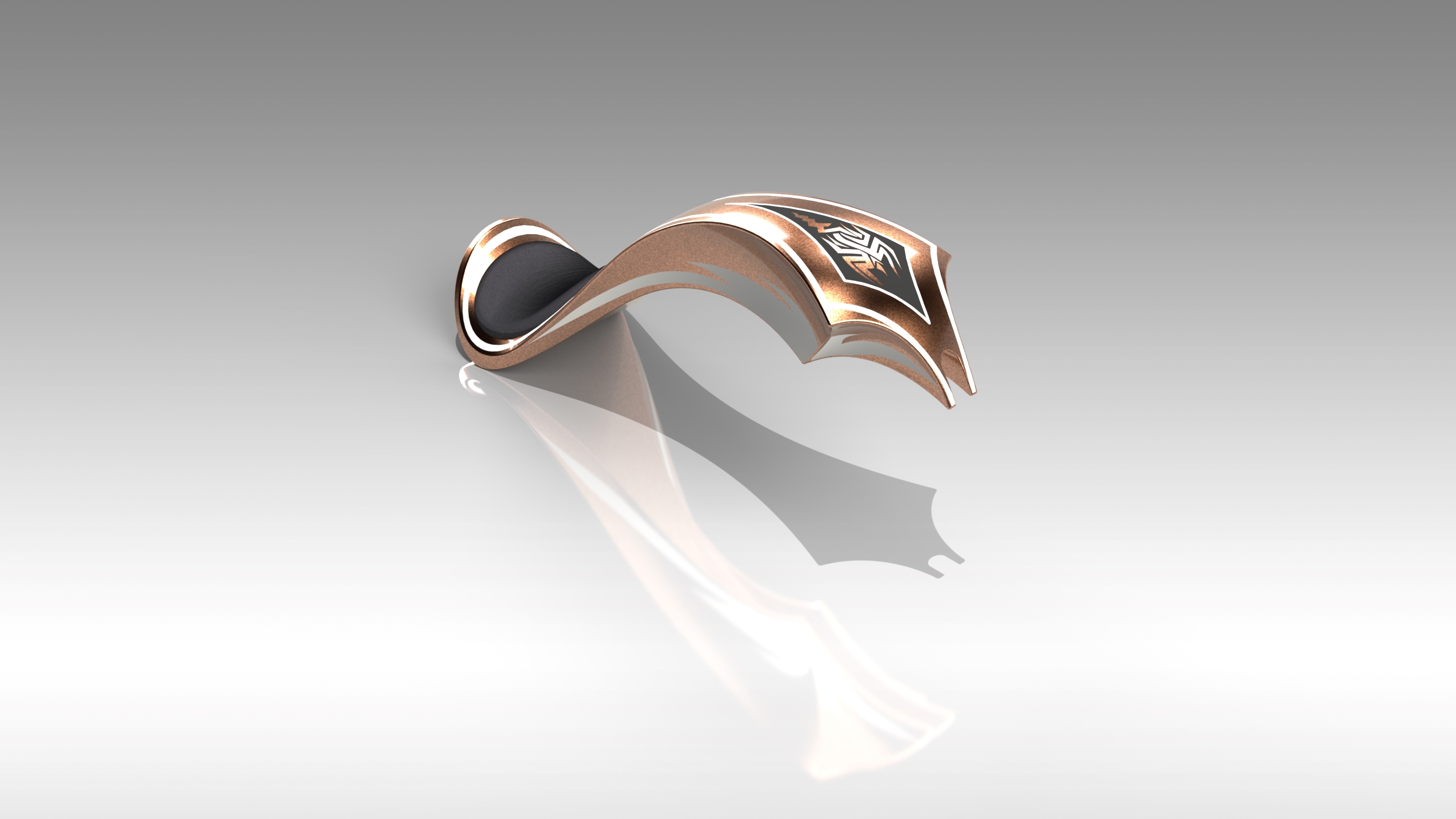
GAS TANK:-
Gas tank is used to store gas in the tank and supply whenever required to engine.
COMMANDS USED:-
- Sketch
- Offset
- Convert entities
- Trim
- Planes
- Sweep surface
- Loft surface
- Fill surface
- Fillet
- Surface trim
- Surface knit
- Sweep cut
- Mirror
SKETCH
The Sketch is a 2D-dimensional representation of the model with the respect to plane/view.
OFFSET
This feature is used to create a one or more sketch entities, selected model edges, or model faces by a specified distance.
CONVERT ENTITIES
This feature is use to create one or more curves in a sketch by projecting an edge, loop, face, curve, or external sketch contour, set of edges, or set of sketch curves onto the sketch plane.
TRIM
Trim entities is used to cut the line from the sketch to create the desired sketch.
PlANE
It is a reference geometry which can be used to create sketches when there is no proper face to create 2D-sketch.
SWEEP SURFACE
This faeture is used to create a surface by using a profile sketch and a path curve/sketch.
SURFACE LOFT
It is used to generate surface based on 3D curve or existing edges.
SURFACE FILL
This feature is used to fill the boundary by selecting a edge sketch.
FILLET
It a feature used to creat rounded egdes.
SURFACE KNIT
This feature is used to join two or more adjacent surfaces together.
SURFACE TRIM
This feature is used to remove unwanted surface from the model. It required a sketch or surface which intersect the surafce needs to be trimmed.
MIRROR
It is a feature used to make a exact replica of selected feature on a user defined plane/face.
ASSEMBLY:-
Initially, the chassis part is inserted in the assembly by using insert part in the option. after that the part is inserted in the assembly environnment fix it. and the other parts of the chopper are inserted
into the assembly and given possible mate condition.

RENDERING:-
Rendering is the process of creating realistic images of the photorealistic model with the envirnment rendering has been done in two ways:-
- PHOTOVIEW 360
- SOLIDWORKS VISUALIZE


LEARNING OUTCOME
Learned various tools for surface modelling & solid modellling.
Leave a comment
Thanks for choosing to leave a comment. Please keep in mind that all the comments are moderated as per our comment policy, and your email will not be published for privacy reasons. Please leave a personal & meaningful conversation.
Other comments...
Be the first to add a comment
Read more Projects by Nikhil KUMAR (19)
Week 9 - Attachment Feature Creation - Challenge 1
AIM:- RIB DESIGN INPUT- COIN HOLDER MODEL Introduction: Rib: Ribs are thin, wall-like features typically designed into the geometry of a part to add internal support to walls or other features like bosses. In a similar fashion, gussets are support features that reinforce areas such as walls or bosses to the floor. Ribs…
16 Apr 2022 04:22 PM IST
Week 8 - Challenge 5 - Core & Cavity Design
CORE & CAVITY DESIGN OF SWITCH BEZEL AIM1. To create the switch bezel plastic component through the given class-A-surface and at theperforming the draft analysis on the model.2. Creat the core and cavity design of the switch bezel component OBJECTIVE• To ensure proper tree structure is followed.• …
14 Nov 2021 01:22 PM IST
Door Arm Rest Week 8 Challenge
AIM: To make a model from the provided class-A surface. INTRODUCTION: CLASS-A SURFACE: A surface made by the designer which is given as an input to the plastic modeller to work on. It is an aesthetic surface and the outermost surface. CLASS-B SURFACE: A surface after a certain thickness from the class-A surface…
13 Jun 2021 12:24 PM IST
Week 8 - Challenge 4 - Coin Holder Design
AIM: To make a model from the provided class-A surface. INTRODUCTION: CLASS-A SURFACE: A surface made by the designer which is given as an input to the plastic modeller to work on. It is an aesthetic surface and the outermost surface. CLASS-B SURFACE: A surface after a certain thickness from the class-A surface…
25 May 2021 03:14 PM IST
Related Courses

Skill-Lync offers industry relevant advanced engineering courses for engineering students by partnering with industry experts.
Our Company
4th Floor, BLOCK-B, Velachery - Tambaram Main Rd, Ram Nagar South, Madipakkam, Chennai, Tamil Nadu 600042.
Top Individual Courses
Top PG Programs
Skill-Lync Plus
Trending Blogs
© 2025 Skill-Lync Inc. All Rights Reserved.


