Modified on
Common Doubts That Arise While Working With Connections

Skill-Lync
The majority of constructions have some kind of joint or connection. With the development of screw cutting techniques, bolted connections became feasible, and utilisation was expedited by, among other things, pitch and thread uniformity. Even today, hundreds of bolts and rivets are still used to join the parts of structures like ships and aeroplanes. Spot welding and welding are other technologies used for large-scale connections. The use of bonding has significantly increased as a result of advancements in adhesive technology and the widespread use of composite materials. Connections may be continuous, if other abutments are present or when plates have a wide surface area.
In this article, you will find the answers to common doubts related to connections.
1. How to generate the CBUSH connection on the door window?
Step - 1 :
- Convert the glass-free edge to curve by using the feat2curve option that is available in the Mesh>perimeters>feat2curve
_1660832234.png)
You can see the curve on the glass end (As shown in the image below)
_1660832311.png)
Step -2 :
- Convert the new curve to the spot line by using the convert option that is available in the Assembly deck.
_1660832394.png)
Step - 3:
- Generate the FE representation (RBE3-CBUSH-RBE3) on the spot line
1) Go to the connection manager.
_1660832484.png)
2) Click the spot line and middle click on your mouse.
- After Middle clicking, you will see another window (As shown in the image below)
_1660832545.png)
3) S is the distance between two cbush elements that value should be less than half of the curve that you had created before. For assigning the S, Right-click on it and click the modify tab. Type the suitable value and press the enter key on your keyboard.
_1660832597.png)
4) Assigning the P1 and P2 (P1 and P2 are the part ids)
_1660832659.png)
- Click the modify tab and Press F1 on your keyboard.
- Select the respective part and middle-click on your mouse.
- You can see the PID of the selected part in the modify tab and click the enter on your keyboard.
- Do the same procedure for assigning PID to P2. (NOTE: Select the respective part for P2).
_1660832721.png)
FE representation settings Tab:
- FE Rep type: You have to select the required connection type in the FE Rep type
_1660832819.png)
- Search distance: Distance between the two parts to be connected. If you know the distance, give that value or else you can give either 50 or 100.
- Leave the other settings as default.
Click apply and realize:
_1660832905.png)
- After realizing the CBUSH connection the output will look like the image shown below:
_1660832958.png)
2. How to Define the specific property for the connection?
- Select the id tab and press the Shift and / on your keyboard
_1660833015.png)
- It will open the respective property tab then you can assign the older id or else you can create the new id also by right-clicking the screen you can see the new option there you can create the new id.
_1660833058.png)
- Double click the required property in the property tab and the selected property ID will be displayed in the ID section.
_1660833091.png)
3. Where to use the different types of Seam weld?
Overlap shell:
- If you have two components that are parallel to each other, you can use this type of seam weld.
_1660833208.png)
Y joint shell :
- If you have two components that are perpendicular to each other, you can use this type of seam weld.
_1660833274.png)
Hope this article gave you clarity on the common doubts regarding connections.
Author

Navin Baskar
Author
Skill-Lync
Subscribe to Our Free Newsletter

Continue Reading
Related Blogs
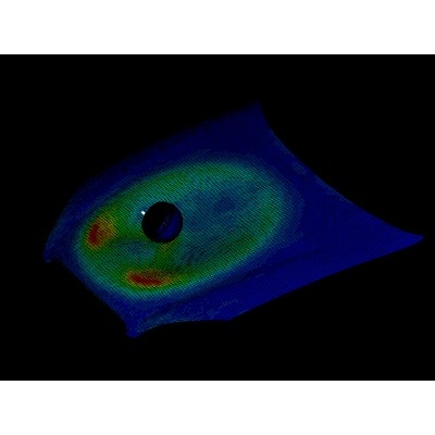
Learn how to render a shock-tube-simulation and how to work on similar projects after enrolling into anyone of Skill-Lync's CAE courses.
09 May 2020
In this blog, read how to design the frontal BIW enclosure of a car (Bonnet) and learn how Skill-Lync Master's Program in Automotive Design using CATIA V5 will help you get employed as a design engineer.
09 May 2020
Tetrahedral is a four- nodded solid element that can be generated through the tria element by creating a volume and also through the existing volume of the geometry. These elements are used where the geometry has high thickness and complexity. The image attached below is a representation of a Tetra element. The Tetra element will have 4 triangular faces with four nodes joining them together
01 Aug 2022
A connector is a mechanism that specifies how an object (vertex, edge, or face) is connected to another object or the ground. By often simulating the desired behaviour without having to build the precise shape or specify contact circumstances, connectors make modeling simpler.
02 Aug 2022
One of the most crucial processes in carrying out an accurate simulation using FEA is meshing. A mesh is composed of elements that have nodes—coordinate positions in space that might change depending on the element type—that symbolise the geometry's shape.
03 Aug 2022
Author
Skill-Lync
Subscribe to Our Free Newsletter
Continue Reading
Related Blogs
Learn how to render a shock-tube-simulation and how to work on similar projects after enrolling into anyone of Skill-Lync's CAE courses.
09 May 2020
In this blog, read how to design the frontal BIW enclosure of a car (Bonnet) and learn how Skill-Lync Master's Program in Automotive Design using CATIA V5 will help you get employed as a design engineer.
09 May 2020
Tetrahedral is a four- nodded solid element that can be generated through the tria element by creating a volume and also through the existing volume of the geometry. These elements are used where the geometry has high thickness and complexity. The image attached below is a representation of a Tetra element. The Tetra element will have 4 triangular faces with four nodes joining them together
01 Aug 2022
A connector is a mechanism that specifies how an object (vertex, edge, or face) is connected to another object or the ground. By often simulating the desired behaviour without having to build the precise shape or specify contact circumstances, connectors make modeling simpler.
02 Aug 2022
One of the most crucial processes in carrying out an accurate simulation using FEA is meshing. A mesh is composed of elements that have nodes—coordinate positions in space that might change depending on the element type—that symbolise the geometry's shape.
03 Aug 2022
Related Courses