Week 8 - Simulation of a backward facing step in OpenFOAM
Aim:- To simulate an incompressible-laminar-viscous flow through backward facing step geometry
Objective:- 1) Simulate the flow without using any grading factor (i.e., GF = 1)
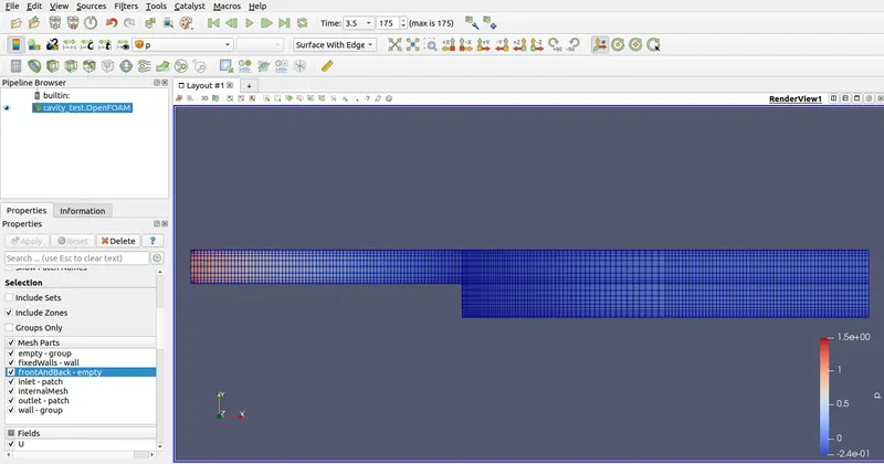
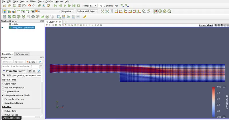
2) Simulate the flow with grading factor of 0.2. The cells should be finer near the walls ( including the step wall ).
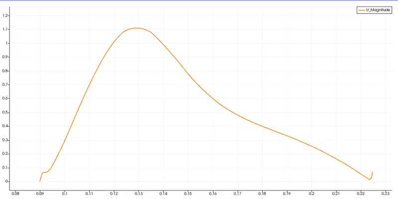
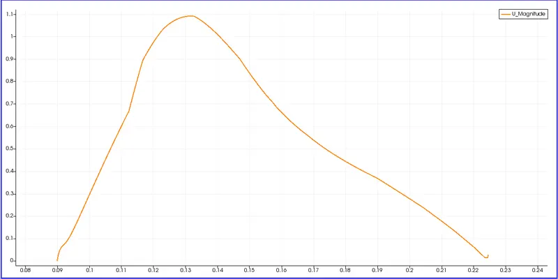
- Measure the velocity profile at 0.085 m from the inlet of the geometry for both case studies and compare. You can use the plot over line tool for this.
- Explain why Grading/Growth factor is essential for meshing.
Mesh specification
- Number of cells along the x direction (longer dimension) = 200
- Number of cells along the longer y direction = 20;
Boundary condition specification
The domain specifications are provided in the following figure.
Procedure:- Inorder to start the simulation, first start the terminal in Linux system by right click and then select the Open Terminal option.
Now we are going to solve the problem using tutorials in openFoam. Type tutorials in the openFoam tutorial directory. To know the list present in the directory just type ‘ls’.
A number of tutorials can be seen from which we have to solve incompressible flow simulation. Now select ‘incompressible’ directory by typing ‘cd incompressible’. To know the list inside the directory again type ‘ls’.
Again a number of solvers can be seen from which we will select ‘icoFoam’ as we need to solve for laminar-viscous flow. IcoFoam is the solver in openFoam which is used as transient solver for incompressible, laminar flow for Newtonian fluids
To select the directory type ‘cd icoFoam’ and type ‘ls’ again to view the list inside the directory.
Here we can see the cavity folder. The cavity section is used to create the required domain and blockmesh. So we will select the cavity folder by typing ‘cd cavity’
Note that do not make any changes in the tutorial folder. Any changes made in the official tutorials may corrupt openFoam and we need to re-install openFoam again
Now we are going to copy the cavity folder and paste it in openFOam run folder by typing ‘cp -r cavity $FOAM_RUN/cavity_test’. After this now open the folder foam run by typing ‘cd $FOAM_RUN’. Here we can see the folder that was copied.
In the cavity_test folder we can see three directories i.e ‘0’ , ‘constant’ & ‘system’
The types of directories inside a case are always the same regardless of which solver we use.
‘0’ – This directory contains the boundary and initial conditions
‘constant’ – This directory houses everything that is constant during the simulation and it also contains the mesh of the object.
‘system’ – This directory contains the solver details
The system directory contains the sub folders namely ‘controlDict’ , ‘fvSchemes’ & ‘fvSolution’
‘controlDict’ – It is the controller of the simulation. It tells about the time-stepping, the name of the solver and the format of the solution.
‘fvSchemes’ – It is the scheme for the solution
‘fvSolution’ – It will show what solver is used internally
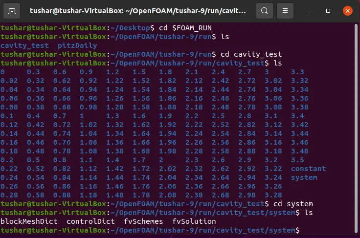
Now we will make changes in the blockMeshDict file as per our problem. To make any change type ‘gedit blockMeshDict’ . The changes that has to be made is shown below. After editing the blockMeshDict file save it and close it.
BlockMeshDict script
/*--------------------------------*- C++ -*----------------------------------*\

  =========                 |

  \\      /  F ield         | OpenFOAM: The Open Source CFD Toolbox

   \\    /   O peration     | Website:  https://openfoam.org

    \\  /    A nd           | Version:  9

     \\/     M anipulation  |

\*---------------------------------------------------------------------------*/

FoamFile

{

    format      ascii;

    class       dictionary;

    object      blockMeshDict;

}

// * * * * * * * * * * * * * * * * * * * * * * * * * * * * * * * * * * * * * //


convertToMeters 1;


vertices

(

    (0 0 0)                             //0

    (0.08 0 0)                       //1

    (0.08 0.01 0)   //2

    (0 0.01 0)                       //3

    (0 0 0.1)                          //4

    (0.08 0 0.1)     //5

    (0.08 0.01 0.1)              //6

    (0 0.01 0.1)     //7

    (0.2 0 0)                          //8

    (0.2 0.01 0)     //9

    (0.2 0 0.1)       //10

    (0.2 0.01 0.1) //11

    (0.08 -0.01 0) //12

    (0.2 -0.01 0)    //13

    (0.08 -0.01 0.1)             //14

    (0.2 -0.01 0.1)               //15

);


blocks

(

    hex (0 1 2 3 4 5 6 7) (80 10 1) simpleGrading (1 1 1)

    hex (1 8 9 2 5 10 11 6) (120 10 1) simpleGrading (1 1 1)

    hex (12 13 8 1 14 15 10 5) (120 10 1) simpleGrading (1 1 1)

);


edges

(

);


boundary

(

    inlet

    {

        type patch;

        faces

        (

            (0 4 7 3)

        );

    }

    outlet

    {

        type patch;

        faces

        (

            (8 9 11 10)

            (8 10 15 13)

        );

    }

    fixedWalls

    {

        type wall;

        faces

        (

            (3 7 6 2)

            (2 6 11 9)

            (0 1 5 4)

            (12 13 15 14)

            (1 12 14 5)

        );

    }

    frontAndBack

    {

        type empty;

        faces

        (

            (4 5 6 7)

            (0 3 2 1)

            (2 9 8 1)

            (6 5 10 11)

            (1 8 13 12)

            (5 14 15 10)

        );

    }

);


mergePatchPairs

(

);


// ********************************************
In the next step we will navigate to the controlDIct folder and specify the simulation time as 200 seconds. Also we will set the value of delta t. While selection of delta t, make sure that the CFL value should be less than 1. Otherwise the solution may be stopped forcibly or it may diverge at the time of converging. After making changes save the file and close it. Below is the script file
ControlDict script
/*--------------------------------*- C++ -*----------------------------------*\

  =========                 |

  \\      /  F ield         | OpenFOAM: The Open Source CFD Toolbox

   \\    /   O peration     | Website:  https://openfoam.org

    \\  /    A nd           | Version:  9

     \\/     M anipulation  |

\*---------------------------------------------------------------------------*/

FoamFile

{

    format      ascii;

    class       dictionary;

    location    "system";

    object      controlDict;

}

// * * * * * * * * * * * * * * * * * * * * * * * * * * * * * * * * * * * * * //


application     icoFoam;


startFrom       startTime;


startTime       0;


stopAt          endTime;


endTime         3.5;


deltaT          0.001;


writeControl    timeStep;


writeInterval   20;


purgeWrite      0;


writeFormat     ascii;


writePrecision  6;


writeCompression off;


timeFormat      general;


timePrecision   6;


runTimeModifiable true;
After this navigate to the ‘0’ folder where we have to define the initial value for pressure and velocity. Below is the script of Pressure and Velocity.
Initial conditions for pressure and velocity
Pressure
/*--------------------------------*- C++ -*----------------------------------*\

  =========                 |

  \\      /  F ield         | OpenFOAM: The Open Source CFD Toolbox

   \\    /   O peration     | Website:  https://openfoam.org

    \\  /    A nd           | Version:  9

     \\/     M anipulation  |

\*---------------------------------------------------------------------------*/

FoamFile

{

    format      ascii;

    class       volScalarField;

    object      p;

}

// * * * * * * * * * * * * * * * * * * * * * * * * * * * * * * * * * * * * * //


dimensions      [0 2 -2 0 0 0 0];


internalField   uniform 0;


boundaryField

{

    inlet

    {

        type            zeroGradient;

    }

    outlet

    {

        type            fixedValue;

        value                           uniform 0;

    }

    fixedWalls

    {

        type            zeroGradient;

    }


    frontAndBack

    {

        type            empty;

    }

}


// ************************************************************************* //
Velocity
/*--------------------------------*- C++ -*----------------------------------*\

  =========                 |

  \\      /  F ield         | OpenFOAM: The Open Source CFD Toolbox

   \\    /   O peration     | Website:  https://openfoam.org

    \\  /    A nd           | Version:  9

     \\/     M anipulation  |

\*---------------------------------------------------------------------------*/

FoamFile

{

    format      ascii;

    class       volVectorField;

    object      U;

}

// * * * * * * * * * * * * * * * * * * * * * * * * * * * * * * * * * * * * * //


dimensions      [0 1 -1 0 0 0 0];


internalField   uniform (0 0 0);


boundaryField

{

    inlet

    {

        type            fixedValue;

        value           uniform (1 0 0);

    }

    outlet

    {

        type            zeroGradient;


    }

    fixedWalls

    {

        type            noSlip;

    }


    frontAndBack

    {

        type            empty;

    }

}


// ************************************************************************* //
Now we can proceed further to set the mesh using ‘blockMesh’ command. After this just check if the mesh has any error by typing ‘checkMesh’.
After getting the confirmation that the Mesh is ok, type ‘icoFoam’. This will start the simulation of our problem.
Now let us view the results in paraView by using ‘paraFoam’ command.
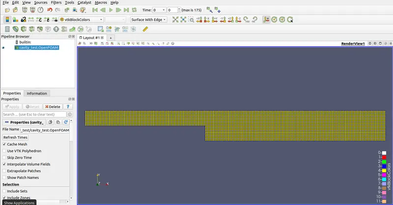
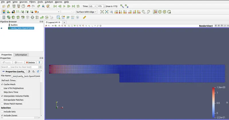
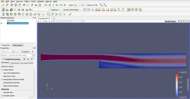
Case 2:-
BlockMeshDict script
/*--------------------------------*- C++ -*----------------------------------*\

  =========                 |

  \\      /  F ield         | OpenFOAM: The Open Source CFD Toolbox

   \\    /   O peration     | Website:  https://openfoam.org

    \\  /    A nd           | Version:  9

     \\/     M anipulation  |

\*---------------------------------------------------------------------------*/

FoamFile

{

    format      ascii;

    class       dictionary;

    object      blockMeshDict;

}

// * * * * * * * * * * * * * * * * * * * * * * * * * * * * * * * * * * * * * //


convertToMeters 1;


vertices

(

    (0 0 0)                             //0

    (0.08 0 0)                       //1

    (0.08 0.01 0)                  //2

    (0 0.01 0)                       //3

    (0 0 0.1)                          //4

    (0.08 0 0.1)                    //5

    (0.08 0.01 0.1)              //6

    (0 0.01 0.1)                    //7

    (0.2 0 0)                          //8

    (0.2 0.01 0)                    //9

    (0.2 0 0.1)                      //10

    (0.2 0.01 0.1)                //11

    (0.08 -0.01 0)                //12

    (0.2 -0.01 0)                   //13

    (0.08 -0.01 0.1)             //14

    (0.2 -0.01 0.1)               //15

);


blocks

(

    hex (0 1 2 3 4 5 6 7) (80 10 1)

    simpleGrading

    (

               1

               ((0.5 0.5 5) (0.5 0.5 0.2))

               1

    )

    hex (1 8 9 2 5 10 11 6) (120 10 1)

    simpleGrading

    (

               ((0.5 0.5 5) (0.5 0.5 1))

               ((0.5 0.5 5) (0.5 0.5 0.2))

               1

    )

    hex (12 13 8 1 14 15 10 5) (120 10 1)

    simpleGrading

    (

               ((0.5 0.5 5) (0.5 0.5 1))

               5

               1

    )

);


edges

(

);


boundary

(

    inlet

    {

        type patch;

        faces

        (

            (0 4 7 3)

        );

    }

    outlet

    {

        type patch;

        faces

        (

            (8 9 11 10)

            (8 10 15 13)

        );

    }

    fixedWalls

    {

        type wall;

        faces

        (

            (3 7 6 2)

            (2 6 11 9)

            (0 1 5 4)

            (12 13 15 14)

            (1 12 14 5)

        );

    }

    frontAndBack

    {

        type empty;

        faces

        (

            (4 5 6 7)

            (0 3 2 1)

            (2 9 8 1)

            (6 5 10 11)

            (1 8 13 12)

            (5 14 15 10)

        );

    }

);


mergePatchPairs

(

);
Conclusion:-
To capture results more accurately, finer mesh is used.
By changing the simple grading factor from 1 to 0.2 the mesh becomes finer and we get an accurate solution.
Why Grading / Growth factor is essential for meshing
Grading factor helps us to adjust the size of the cell at the starting or at the end of the block. So area where we need and accurate result, we can put finer mesh and the area which is not much important there we can use coarser mesh.