Week 3 - 2D meshing for Sheet metal
Objective:- For the given Hood model, Take the mid surface for all the components after checking the geometrical errors and mesh the mid surface with the given element Quality criteria.
S. No | Quality Criteria | Value |
1 | Target/Average length | 5 |
2 | Minimum Length | 2 |
3 | Maximum Length | 7 |
4 | Aspect | 3 |
5 | Warpage | 15 |
6 | Skewness | 45 |
7 | Jacobian | 0.7 |
8 | Minimum Quad Angle | 45 |
9 | Maximum Quad Angle | 135 |
10 | Minimum Tria Angle | 30 |
11 | Maximum Tria Angle | 120 |
10 | Tria Percentage | 15 |
All the 2D elements in the model should clear the above-mentioned quality criteria and the features in the model have to be captured properly with good mesh flow. After meshing the Mid surface, Thickness must be assigned to Mid-surface
Procedure:-
Importing the given model in ANSA.
Go to ‘File -> Open’ and select the model.
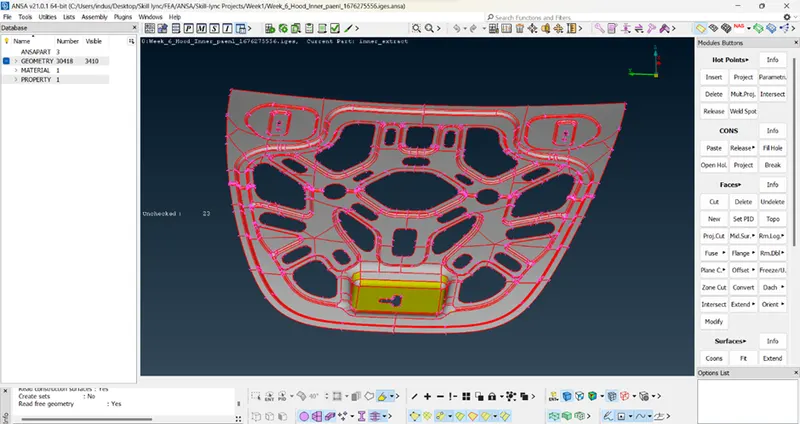
Resolution of cons
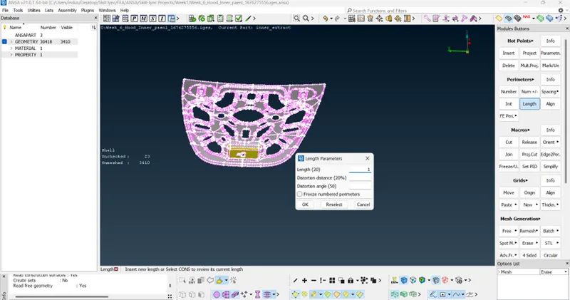
Cons resolution is done to get a smooth distribution of cons over the geometry. To perform this Goto Mesh module -> Perimeters -> Length and then set the value of 1 and click ok.
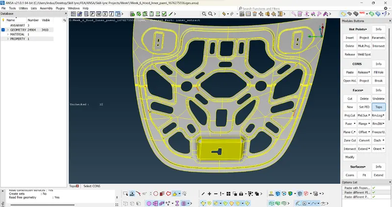
Topo cleanup
To resolve the unwanted single cons, Topo cleanup is performed.
After performing Topo cleanup, maximum single cons are resolved.
Checking for any geometrical errors in the model.
Checking if there are any geometrical errors present in the model.
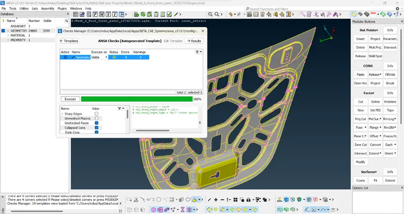
Go to ‘Checks -> Geometry’ and then check the single cons box which was unchecked and then execute the process. After execution, the errors will be shown as shown below.
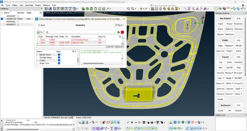
To resolve the errors shown, right click on the errors and then select Fix option.
After Fixing the above issues, now execute the geometrical checks again for the model.
Extracting the mid-surface of the model.
Before extracting the mid-surface of the model, we need to measure the thickness.
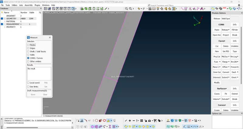
Since the model has constant thickness throughout, we will select Offset to extract the mid surface.
Mid-surface is created. To use it to do the meshing as it does not affect the parent geometry but carry out the preprocessing simulation. The mid surface is created by using the module buttons in Topo mode. In module buttons, click ‘Offset -> Faces’ in Faces Module click on Face for which the mid surface is to be created. Click middle-click on the mouse to confirm and a dialog box appears in which the mid surface location is to be given.
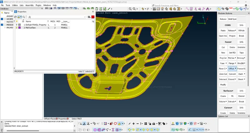
By providing the offset value, the mid surface will be created as shown above.
Meshing
Before proceeding with the mesh, the quality criteria and meshing parameters are to be given to meet the requirements. The Quality criteria are opened by either clicking F11 on the keyboard or by clicking Utilities -> Quality criteria.
The Quality criteria which are given are stated below should be entered in the shell icon.
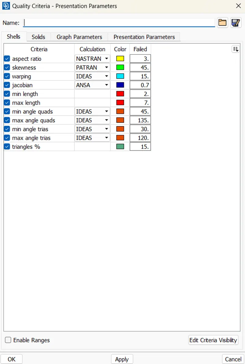
To create a mesh for any model, in modules select mesh. Click ‘Modules -> Mesh. Once the mesh module buttons are opened and seen. Initially the mesh can be created by using tools like Hot points, Perimeters, Mesh Generation, Shell Mesh, Elements.
Firstly when mid surface is opened in mesh mode, click Length in Perimeters. The procedure is as follows Length -> Perimeters, Macros. Select the entire mesh and confirm it, once it is done a dialog box appears stating the length as 3 in both perimeters and macros simultaneously.
In mesh generation, select Best and select the element to mesh and confirm it.
There might me some areas where some of the mesh have some Off elements. To remove the off elements or to reduce them Reconstruct option is used. It can be seen in Shell Mesh -> Reconstruct.
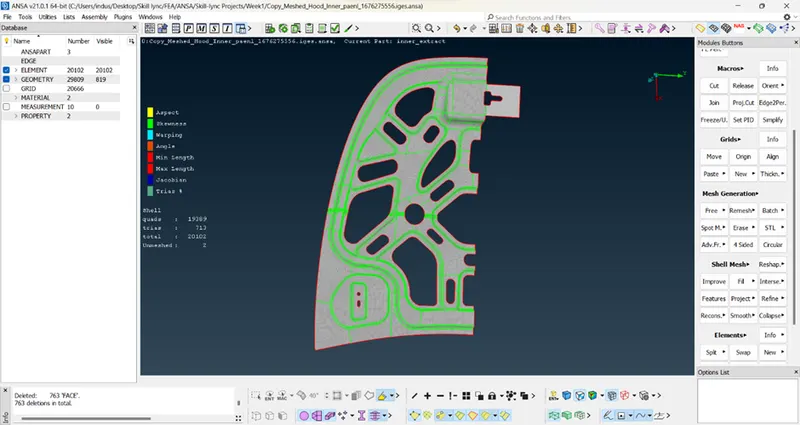
Since the model is symmetric about y-axis, we will mesh half the model and then mirror the entities.
Meshing of Half Part
Mirroring of half part
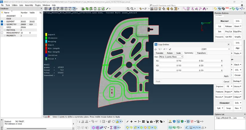
To mirror the entities, Goto ‘Transform -> Copy’.
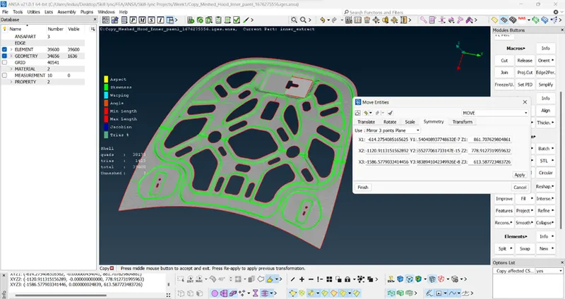
Select all the entities and middle click the mouse. Select ‘Symmetry’ option and under that select ‘Mirror 3 points plane’. Now select the three points about which we have to perfrom mirror.
Completely meshed part
The thickness of the mesh can be added in the property icon and by selecting the part to which the thickness needs to be given.
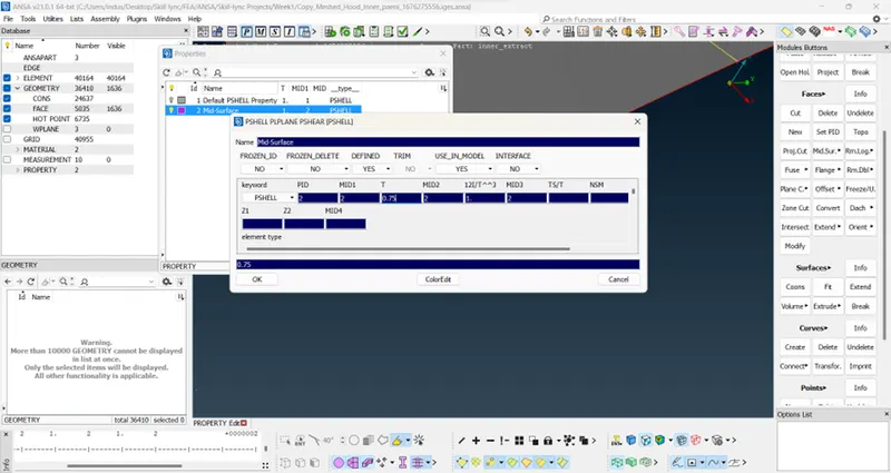
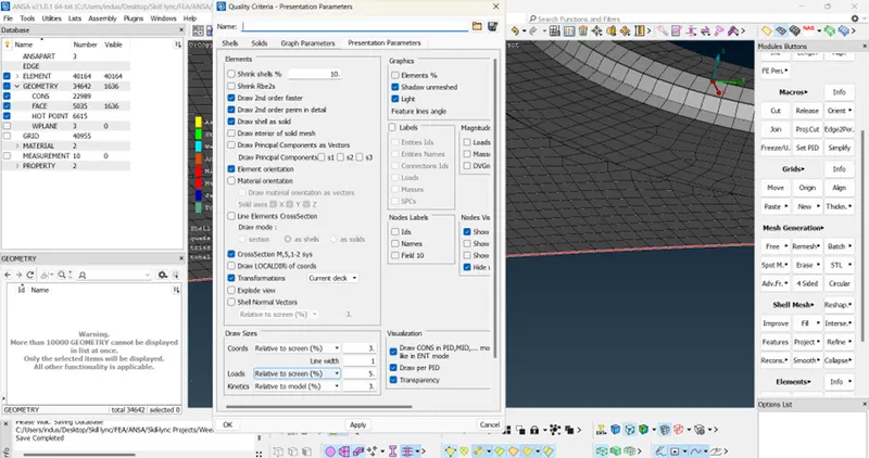
To check if the model shows the given thickness, got to ‘Quality Criteria -> Presentation Parameters -> Draw Shell as Solid -> OK.
Conclusion:-
The basics of ANSA can be learned by practicing in this model. The following outcomes are learned.
- Geometrical Clean-up
- Topological Correcting
- Creating of Mid Surface
- Correction of mesh errors
- Adding the Thickness
Link of the Model:- https://drive.google.com/file/d/1LwXCkHREGq5baBDl8fL9aEZKSOFuQvRz/view?usp=share_link