Week 8 - Simulation of a backward facing step in OpenFOAM
Aim:-The aim of this project is to create the geometry for incompressible cavity flow
problem in OpenFOAM and also to simulate the flow through a backward facing step for
different grading factor using icoFOAM solver.
OpenFOAM code:-
● BlockMeshDict File:-In the following code we have created the required geometry
for grading factor 0.2 & we also we have assign the boundary condition.This we
did in the blockMeshDict file of system folder in cavity tutorial.
/*--------------------------------*- C++
-*----------------------------------*\
========= |
\\ / F ield | OpenFOAM: The Open Source CFD Toolbox
\\ / O peration | Website: https://openfoam.org
\\ / A nd | Version: 7
\\/ M anipulation |
\*------------------------------------------------------------------------
---*/
FoamFile
{
version 2.0;
format ascii;
class dictionary;
object blockMeshDict;
}
// * * * * * * * * * * * * * * * * * * * * * * * * * * * * * * * * * * * *
* //
convertToMeters 1;
vertices
(
(0 0 0)
(1 0.08 0 0)
(0.08 0.005 0)
(0 0.005 0)
(0.08 0.01 0)
(0 0.01 0)
(0.2 0.01 0)
(0.2 0.005 0)
(0.2 0 0)
(0.2 -0.01 0)
(0.08 -0.01 0)
(0 0 0.001)
(0.08 0 0.001)
(0.08 0.005 0.001)
(0 0.005 0.001)
(0.08 0.01 0.001)
(0 0.01 0.001)
(0.2 0.01 0.001)
(0.2 0.005 0.001)
(0.2 0 0.001)
(0.2 -0.01 0.001)
(0.08 -0.01 0.001)
);
blocks
(
hex (0 1 2 3 11 12 13 14) (200 10 1) simpleGrading (0.2 1.2 1)
hex (3 2 4 5 14 13 15 16) (200 10 1) simpleGrading (0.2 0.2 1)
hex (2 7 6 4 13 18 17 15) (200 10 1) simpleGrading (1.2 0.2 1)
hex (1 8 7 2 12 19 18 13) (200 10 1) simpleGrading (1.2 1.2 1)
hex (10 9 8 1 21 20 19 12) (200 10 1) simpleGrading (1.2 0.2 1)
);
edges
(
);
boundary
(
inlet
{
type patch;
faces
(
(0 11 14 3)
(3 14 16 5)
);
}
outlet
{
type patch;
faces
(
(9 8 19 20)
(8 7 18 19)
(7 6 17 18)
);
}
frontAndBack
{
type empty;
faces
(
(0 3 2 1)
(3 5 4 2)
(10 1 8 9)
(1 2 7 8)
(2 4 6 7)
(11 12 13 14)
(14 13 15 16)
(21 20 19 12)
(12 19 18 13)
(13 18 17 15)
);
}
noslipwalls
{
type wall;
faces
(
(5 16 15 4)
(4 15 17 6)
(0 1 12 11)
(10 21 12 1)
(10 9 20 21)
);
}
);
mergePatchPairs
(
);
//
*************************************************************************
//
● ControlDict File:-In the following code we have to assign the start time, end time as
well as a time step. This we did in the controlDict file of the system folder in the cavity
tutorial.
/*--------------------------------*- C++
-*----------------------------------*\
========= |
\\ / F ield | OpenFOAM: The Open Source CFD Toolbox
\\ / O peration | Website: https://openfoam.org
\\ / A nd | Version: 7
\\/ M anipulation |
\*------------------------------------------------------------------------
---*/
FoamFile
{
version 2.0;
format ascii;
class dictionary;
location "system";
object controlDict;
}
// * * * * * * * * * * * * * * * * * * * * * * * * * * * * * * * * * * * *
* //
application icoFoam;
startFrom startTime;
startTime 0;
stopAt endTime;
endTime 0.01;
deltaT 1.33e-5;
writeControl timeStep;
writeInterval 20;
purgeWrite 0;
writeFormat ascii;
writePrecision 6;
writeCompression off;
timeFormat general;
timePrecision 6;
runTimeModifiable true;
//
*************************************************************************
//
● Velocity File:-In the following code we have assigned the value for velocity for
boundary conditions and also for different patchs. This we did in the U file of
the constant folder in the cavity tutorial.
/*--------------------------------*- C++
-*----------------------------------*\
========= |
\\ / F ield | OpenFOAM: The Open Source CFD Toolbox
\\ / O peration | Website: https://openfoam.org
\\ / A nd | Version: 7
\\/ M anipulation |
\*------------------------------------------------------------------------
---*/
FoamFile
{
version 2.0;
format ascii;
class volVectorField;
object U;
}
// * * * * * * * * * * * * * * * * * * * * * * * * * * * * * * * * * * * *
* //
dimensions [0 1 -1 0 0 0 0];
internalField uniform (0 0 0);
boundaryField
{
moving wall
{
type fixedValue;
value uniform (1.5 0 0);
}
outlet
{
type zeroGradient;
}
frontAndBack
{
type empty;
}
noslipwalls
{
type fixedValue;
value uniform(0 0 0);
}
}
//
*************************************************************************
//
● Pressure File:-In the following code we have assigned the value for pressure for
boundary conditions and aslo for different patchs. This we did in the p file of
the constant folder in the cavity tutorial.
/*--------------------------------*- C++
-*----------------------------------*\
========= |
\\ / F ield | OpenFOAM: The Open Source CFD Toolbox
\\ / O peration | Website: https://openfoam.org
\\ / A nd | Version: 7
\\/ M anipulation |
\*------------------------------------------------------------------------
---*/
FoamFile
{
version 2.0;
format ascii;
class volScalarField;
object p;
}
// * * * * * * * * * * * * * * * * * * * * * * * * * * * * * * * * * * * *
* //
dimensions [0 2 -2 0 0 0 0];
internalField uniform 0;
boundaryField
{
inlet
{
type zeroGradient;
}
outlet
{
type fixedValue;
value uniform 0;
}
frontAndBack
{
type empty;
}
noslipwalls
{
type zeroGradient;
}
}
//
*************************************************************************
//
Results:-
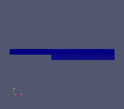
● The following image shows the Mesh
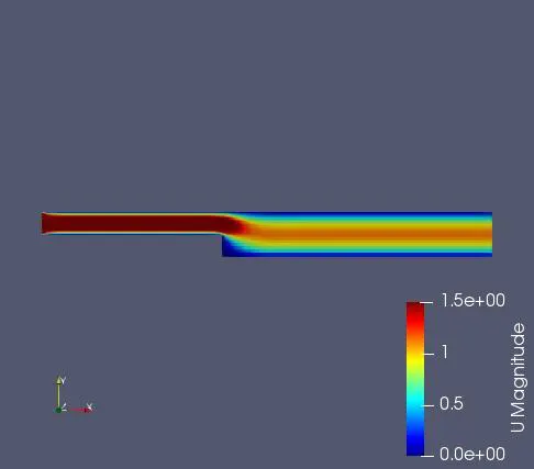
● For grading factor=0.2
Velocity profile:-
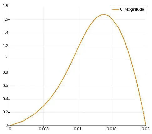
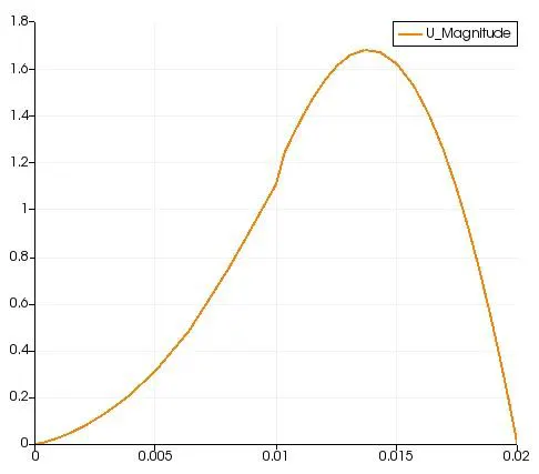
Line Plot:-
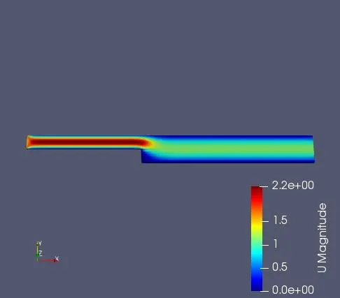
● Mesh Code for grading factor=0.5
blocks
(
hex (0 1 2 3 11 12 13 14) (200 10 1) simpleGrading (0.5 2 1)
hex (3 2 4 5 14 13 15 16) (200 10 1) simpleGrading (0.5 0.5 1)
hex (2 7 6 4 13 18 17 15) (200 10 1) simpleGrading (2 0.5 1)
hex (1 8 7 2 12 19 18 13) (200 10 1) simpleGrading (2 2 1)
hex (10 9 8 1 21 20 19 12) (200 10 1) simpleGrading (2 5 1)
);
Velocity profile:-
● Mesh Code for grading factor=0.8
blocks
(
hex (0 1 2 3 11 12 13 14) (200 10 1) simpleGrading (0.8 2 1)
hex (3 2 4 5 14 13 15 16) (200 10 1) simpleGrading (0.8 0.8 1)
hex (2 7 6 4 13 18 17 15) (200 10 1) simpleGrading (2 0.8 1)
hex (1 8 7 2 12 19 18 13) (200 10 1) simpleGrading (2 2 1)
hex (10 9 8 1 21 20 19 12) (200 10 1) simpleGrading (2 0.8 1)
);
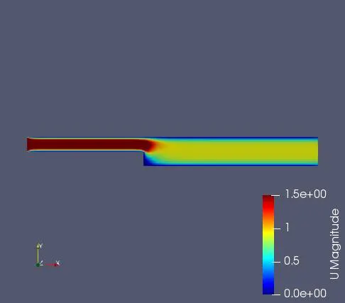
Velocity profile:-
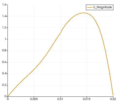
Line Plot:-
● Mesh Code for grading factor=1
blocks
(
hex (0 1 2 3 11 12 13 14) (200 10 1) simpleGrading (1 1 1)
hex (3 2 4 5 14 13 15 16) (200 10 1) simpleGrading (1 1 1)
hex (2 7 6 4 13 18 17 15) (200 10 1) simpleGrading (1 1 1)
hex (1 8 7 2 12 19 18 13) (200 10 1) simpleGrading (1 1 1)
hex (10 9 8 1 21 20 19 12) (200 10 1) simpleGrading (1 1 1)
);
Velocity profile:-
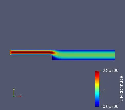
Line Plot:-
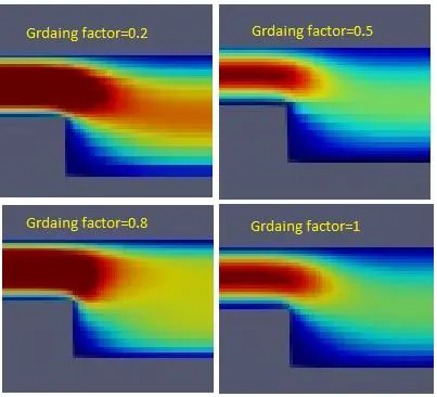
● Comparison of velocity contour for different grading factors:-
Conclusion:-
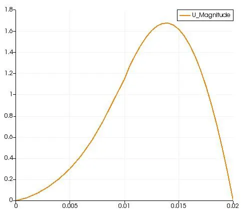
● Line plot:-All above line plots is been obtained at x=0.085 & y=0.01, we get
different plots for different grading factors at the same location.
● Velocity contour:-All above velocity contour is obtained for different grading factor
like at 1,0.2,0.5 and 0.8.
● And also after observing the above comparison we can conclude that grading
factor affects the results. Finer grading factor at the wall create more clear
simulation.